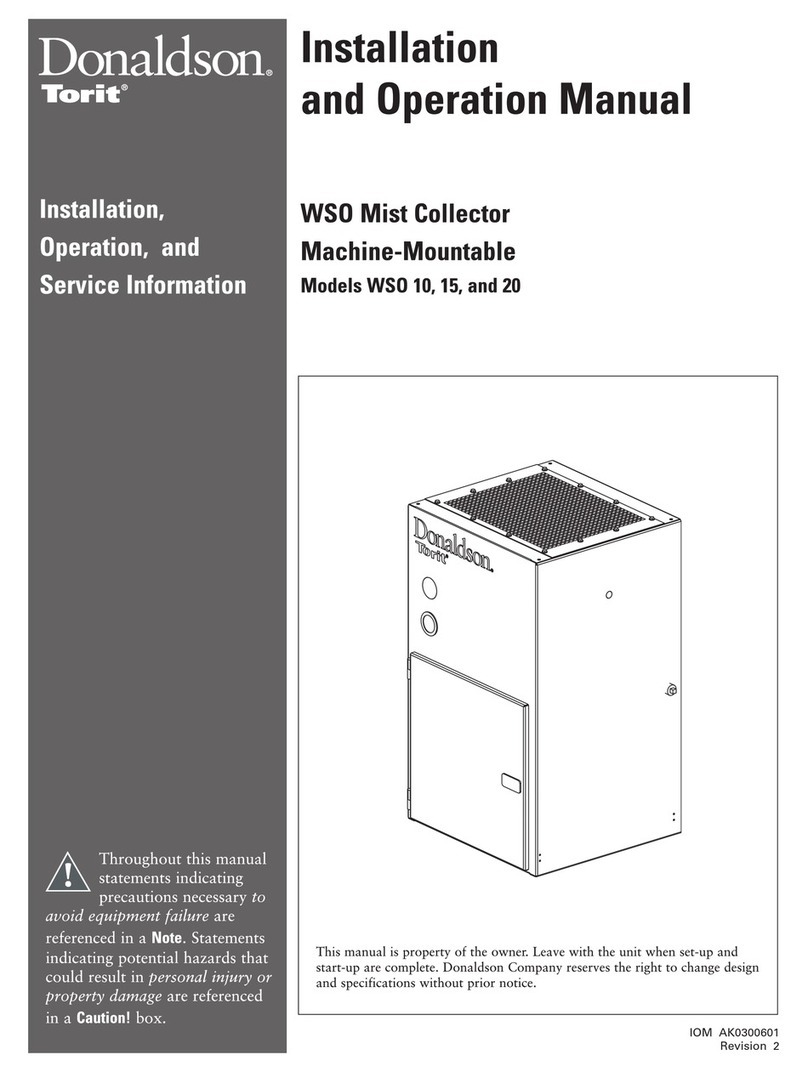
Donaldson Torit Dryflo MMA User manual

IOM 7236900 (ENG)
Revision 7
English
Master Language
Dryo® Machine Mountable Mist
Collector
MMA and MMB
Installation and Operation Manual
Installation, Operation and Service Manual
This manual contains specic precautions related to worker safety. The hazard alert image denotes safety
related instructions and warnings in this manual. DO NOT install, operate, or perform maintenance on this
collector until you have read and understood the instructions, precautions and warnings contained within this
manual.
IOM 7236900 (ENG)
Revision 7
Englis
Master Language

i
Donaldson Company, Inc.
The Safety Alert Symbol indicates a hazardous situation which, if not avoided could
result in death or serious injury. Obey all safety messages following this symbol to
avoid possible injury or death. The possible hazards are explained in the associated
text messages.
NOTICE indicates a potential situation or practice which is not expected to
result in personal injury, but which if not avoided, may result in damage to
equipment.
This manual has been supplied to assist with the installation, operation and maintenance for
the collector purchased. Please read the manual before installing, operating, or performing
maintenance on the collector as it contains specic precautions for worker safety. It is the
owner’s responsibility to ensure that this manual is available for use by installers, operators and
maintenance personnel that will be working with this collector. This manual is the property of the
owner and should be left with the collector when installation has been completed. DO NOT operate
this collector until you have read and understood the instructions and warnings located in the
installation and operation manual.
For additional copies of this manual, contact Donaldson Torit.
IMPORTANT NOTES

Dryo, MMA and MMB
ii
Contents
IMPORTANT NOTES.......................................................................................................................................................................i
1 Safety Communication ..............................................................................................................................................................1
2 Product Description...................................................................................................................................................................3
Standard Equipment...........................................................................................................................................................3
Machine Mount ...........................................................................................................................................................3
Inlet Gasket .................................................................................................................................................................3
Integral Housed Fan....................................................................................................................................................3
Minihelic®Gauge .........................................................................................................................................................3
Exhaust Pack ..............................................................................................................................................................3
Options and Accessories....................................................................................................................................................4
Inlet Hopper with Impact Separator.............................................................................................................................4
Inlet Hopper with Flex-Duct .........................................................................................................................................4
Drain Collection Container ..........................................................................................................................................4
Junction Box................................................................................................................................................................4
HEPA Filter ..................................................................................................................................................................4
Inlet Hopper with Vibration Isolators ...........................................................................................................................4
Inlet Hopper with Legs.................................................................................................................................................4
Collector Stand............................................................................................................................................................4
Cart..............................................................................................................................................................................4
Inlet Hopper with Gussets ...........................................................................................................................................4
3 Operation...................................................................................................................................................................................5
4 Product Service.........................................................................................................................................................................6
Operational Checklist .........................................................................................................................................................6
Filter Replacement .............................................................................................................................................................6
Integral Housed Fan...........................................................................................................................................................8
Minihelic Gauge..................................................................................................................................................................8
Options and Accessories Replacement..............................................................................................................................9
Inlet Hopper with Impact Separator.............................................................................................................................9
Drain Collection Container ........................................................................................................................................10
Troubleshooting................................................................................................................................................................11
Appendix A - Installation................................................................................................................................................................13
Installation ........................................................................................................................................................................14
Electrical Wiring................................................................................................................................................................15
Machine Installation..........................................................................................................................................................16
Integral Housed Fans .......................................................................................................................................................18
Minihelic Gauge................................................................................................................................................................19
Exhaust Pack....................................................................................................................................................................19
Motor Starter.....................................................................................................................................................................19
Options and Accessories..................................................................................................................................................20
Pre-Wired Collectors ........................................................................................................................................................27
Unwired Collectors ...........................................................................................................................................................27
Start-up / Commissioning .................................................................................................................................................28
Decommissioning Collector..............................................................................................................................................29
Product Information ..........................................................................................................................................................30
Service Notes ...................................................................................................................................................................31
Donaldson Industrial Air Filtration Warranty..............................................................................................................................32
1
Donaldson Company, Inc.
Improper operation of mist collectors and/or mist control systems may contribute to conditions in a work area or
facility which could result in severe personal injury, and product or property damage. All mist collection equipment
should be used only for its intended purpose and should be properly selected and sized for its intended use.
Process owners have important responsibilities relating to identifying and addressing potential hazards in their
processes. When the potential for handling combustible mist exists within a process the process owner should
include combustion hazards in their risk management activities and should comply with applicable codes and
standards related to combustible mist.
Electrical installation must be performed by a qualied electrician.
This equipment is not designed to support site ducts, piping, or electrical services. All ducts, piping, or electrical
services must be adequately supported to prevent injury and/or property damage.
Site selection must account for wind, seismic zone, and other load conditions.
Equipment may reach peak sound pressure levels above 80 dB (A). Noise levels should be considered when
selecting collector location.
Most mists present safety and health hazards that require precautions. Wear eye, respiratory, head and other
protection equipment suitable for the type of mist.
Some components may be heavier than they appear. Use appropriate lifting methods to avoid personal injury and/or
property damage.
1 Safety Communication

Dryo, MMA and MMB
2
Combustible Mist Hazards
Among other considerations, the current NFPA standards require owners whose processes involve potentially combustible
materials to have a current Dust Hazard Analysis, which can serve as the foundation for their process hazard mitigation strategy.
Mitigation may include but is not limited to:
• Prevention of all ignition sources from entering any dust collection equipment.
• Selection and implementation of re and explosion mitigation, suppression, and isolation strategies appropriate for the
risks in their process.
• Development and use of work practices to maintain safe operating conditions, and to ensure combustible dust does not
accumulate within their plant or process equipment.
Donaldson designs, manufactures, and sells industrial air ltration products for a wide variety of applications. Some applications
may include processes or materials with inherent re and explosion hazards. Donaldson is neither an expert nor a certied
consultant in re, spark, or explosion detection, suppression, or control. Donaldson does not provide engineering consulting
services related to process or dust hazard analyses, or code and standard compliance. Complying with applicable codes and
standards and managing the risks associated with the process or materials remains the responsibility of the process owner/
operator. Donaldson may provide referrals to consultants, suppliers of equipment or services related to the detection and/
or mitigation of sparks, res and/or explosions, but Donaldson does not assume responsibility for any such referrals, nor does
Donaldson assume any liability for the tness of a mitigation strategy or product for a particular installation or application. The
process owner’s nal selection of dust collectors and risk mitigation strategies should be based on the outcome of a Dust Hazard /
Process Hazard Analysis performed by the process owner. Although early engagement of a dust collector supplier provides helpful
insights on the availability and features of various products, process owners should consult with a combustible dust expert and/or a
process safety expert before making actual product and mitigation strategy selections.
Donaldson recommends that all industrial air ltration system designs be reviewed and approved by an expert consultant who is
responsible for the integrity of the system design and compliance with applicable codes and standards. It is the process owner’s
responsibility to understand the risks in their process and mitigate those risks in accordance with all applicable laws, regulations
and standards, including those published by the NFPA. Donaldson also recommends that proper maintenance and housekeeping
procedures and work practices be evaluated, developed, and followed to maintain any industrial air ltration products in safe
operating condition.
Many factors beyond the control of Donaldson can affect the use and performance of Donaldson products in a particular
application, including the conditions under which the product is used. Since these factors are uniquely within the user’s knowledge
and control, it is essential the user evaluate the Donaldson products to determine whether the product is t for the particular
purpose and suitable for the user’s application. All products, product specications, and data (airow, capacity, dimensions, or
availability) are subject to change without notice, and may vary by region or country.

3
Donaldson Company, Inc.
The Dryo mist collector, Models MMA and MMB, mount directly to a machining center to collect airborne mist such as oil, water-
soluble, and synthetic coolant from machining operations. Three stages of ltration, plus an optional HEPA lter, provide a cleaner,
healthier work environment as well as a more cost effective means of mist collection. With airow capacities from 390 to 800 cfm,
the Dryo is a strategic component to meeting industrial and government air-quality standards. The high efciency lter cartridges
allow air and coolants to be recycled and the cartridge efciency actually increases as the collector operates.
Designed to increase the versatility of the collector, standard options include inlet hoppers, impact separators, drain collection
methods and an adjustable stand. A variety of lter media specically designed for mist collection, from heavy liquid-load to heavy
particulate-load applications, is also available.
Intended Use
Airborne mist is small droplets of liquid suspended in the air. Dryo mist collectors are widely used in machine tool operations
using metalworking uids. Metalworking uids include straight oil, water-soluble coolants, soluble oil, and semi-synthetic coolants.
These uids perform a variety of functions such as lubricating or cooling the part or the tool, ushing chips away from the part, and
suppressing dust and smoke. Oils and coolants allow machines to operate faster and tools to last longer resulting in high quality
parts.
Mist is created two ways: mechanical action or thermal effects. Mechanical action refers to aerosol used for light lubrication and
generally creates mist greater than one micron in size. Thermal effects occur when heat vaporizes the coolant; the vapor cools and
recondenses into a mist. Thermal effects create mist from 0.01 to 1 micron in size. Other contaminants, such as dust from the part
or the tool or smoke from the combustion of the oil or coolant are also generated when using metalworking uids.
The Dryo can collect some dust with the mist; however, it should not be operated without mist. The collector is not designed to
handle water mist alone as water vapor will pass through the lters. The extremes of very heavy oil and light, thin oil should be
avoided. Very heavy oil, similar to tar consistency, will not drain while very light, thin oil, may evaporate.
2 Product Description
Standard Equipment
Machine Mount
The air inlet also serves the collector as a drain, collected mist droplets drain back into the machine center. Machine mounting, or
collection at the source is the most efcient means of mist collection.
Inlet Gasket
Used on machine centers that have a large, at unobstructed top surface.
Integral Housed Fan
The integrated fan assembly provides airow for the collector.
Minihelic®Gauge
The Minihelic is a differential pressure gauge used to measure the pressure difference between the clean- and dirty-air plenums
and provides a visual display of lter change requirements.
Exhaust Pack
The exhaust pack provides an exit for clean air with additional HEPA and DOP lter options.

Dryo, MMA and MMB
4
Options and Accessories
Inlet Hopper with Impact Separator
Impact separators are available for remote-mounted collectors in operations generating large amounts of small particulate such as
surface grinding, polishing and high-speed cutting.
Inlet Hopper with Flex-Duct
Available for ceiling mounted collectors or collectors on customer-supplied stands. Included components are a 6-in diameter collar,
10-ft exible duct, two 6-in hose clamps and a 6-in mounting collar.
Drain Collection Container
The drain collection container is available for an impact separator only. The semi-clear one-gallon collection container attaches to
the bottom of the impact separator and collects small particles and coolant.
Junction Box
This option offers quick and easy wiring to the collector. The three phase motor is prewired to a customer requested voltage per
order. Labeled voltage on junction box should be veried to match supply voltage at installation.
HEPA Filter
The optional HEPA lter is recommended for applications using straight or mineral oil machining uids that generate smoke or
other extremely small particulate and is used in place of the standard exhaust pack.
MMA Only:
Inlet Hopper with Vibration Isolators
A vibration isolation kit for top-mounted collectors installed on machine centers sensitive to vibration. The kit includes four isolators,
a support frame, hopper, 6-in diameter exible duct and a duct collar with mounting ange and two hose clamps.
Inlet Hopper with Legs
This option is for machine centers that do not allow the collector to mount ush to the top. A leg mounted to the left side of the
collector and a hopper mounted to the right side provide a raised, level surface on the machine center.
Ceiling Mount
Collector can be suspended or hung from overhead supports.
Collector Stand
For applications with limited mounting surfaces, an adjustable stand is available. The stand’s base is bolted securely to the oor.
After attaching collector, the stand height can be adjusted from 84 to 102-in.
Cart
Available for applications requiring a mobile mist collector.
MMB Only:
Inlet Hopper with Gussets
This option is for machine centers that do not allow the collector to mount ush to the top. A leg mounted to the left side of the
collector and a hopper mounted to the right side provide a raised, level surface on the machine center.

5
Donaldson Company, Inc.
During normal operation, contaminated air enters the collector through the dirty-air inlet on the bottom of the unit. The air passes
through a reusable rst-stage lter designed to collect and coalesce large droplets and particles. Smaller mist droplets pass to a
second-stage lter wrap where the small droplets coalesce into larger droplets.
The third and most efcient stage of ltration is the pleated lter specically designed to collect, coalesce, and drain ne mist. As
the mist coalesce, the droplets are big enough to run down the element and drain back into the collector. The droplets will drain
on both the inside and outside of the lter cartridge. Liquid that collects on the inside of the cartridge drains back into the machine
center. Clean, mist-free air exits the lter cartridge and discharges near the top of the collector.
Collector Operation
Electrical work during installation, service or maintenance must be performed by a qualied electrician and comply
with all applicable national and local codes.
Turn power off and lock out all power before performing service or maintenance work.
Turn compressed air supply off, bleed and lock out lines before performing service or maintenance work.
Check that the collector is clear and free of all debris before starting.
Do not install in classied hazardous atmospheres without an enclosure rated for the application.
clean-air outlet
clean-air plenum
exhaust pack
third-stage lter
second-stage
lter wrap
large droplets
dirty-air inlet
and collected mist drain
large droplets
rst-stage lter
fan motor
fan
3 Operation

Dryo, MMA and MMB
6
Most mists present safety and health hazards that require precautions. Wear eye, respiratory, head and other
protection equipment suitable for the type of mist.
Use proper safety and protective equipment when removing contaminants and lters.
Dirty lters may be heavier than they appear. Use appropriate lifting methods to avoid personal injury and/ or property
damage.
Turn power off and lock out all power before performing service or maintenance work.
Do not operate with missing or damaged lters
Filter Replacement
4 Product Service
Operational Checklist
1. Monitor the physical condition of the collector and repair or replace any damaged components.
Routine inspections will minimize downtime and maintain optimum system performance. This is particularly important on
continuous-duty applications.
2. Monitor pressure drop across lters.
Abnormal changes in pressure drop may indicate a change in operating conditions and possibly a fault to be corrected. If the
pressure gauge is in the red zone, the second-stage lter wrap or third-stage lter cartridge may need replacement. In some
applications, it may be necessary to replace the second-stage lter wrap two to three times during the life of a single, third-
stage lter cartridge. To detemine if the second-stage lter wrap needs replacing, install a clean wrap, restart the collector, and
check the pressure gauge reading. If the gauge is now in the green zone, continue to operate the collector with the new wrap.
If the gauge still reads in the red zone, the lter cartridge needs replacement.
3. Monitor exhaust. Exhaust should remain visually clean throughout lter life. If leaks are visible, check the lter cartridge and
optional HEPA lter for positive gasket seals.
4. Monitor hopper drainage. If slow or stopped, check hopper for obstructions and clean as necessary. Check rst-stage lter and
clean as required.
5. Monitor second-stage lter wrap.
During any service activities there is some potential for exposure to the mist in the collector. Most mists present
safety and health hazards that require precautions. Wear eye, respiratory, head and other protection equipment
suitable for the type of mist when performing any service activities.
Use appropriate access equipment and procedures. Note the standard collector is not equipped with access
platforms unless noted on the specication drawings.
LOCK-OUT all energy sources prior to performing any service or maintenance on the equipment.
Electrical service or maintenance work must be performed by a qualied electrician and comply with all applicable
national and local codes.

Donaldson Company, Inc.
7
First-Stage Filter
First-Stage Filter Replacement
rst-stage lter
third-stage lter
cartridge with
second-stage
lter wrap
1. Remove the lter cartridge by pulling the lter retention lever
out and down to a horizontal position. Remove lter cartridge
from collector.
2. Pull wrap from lter cartridge and dispose of properly.
3. Install new wrap aligning the top of the wrap to the top of the
cartridge. Fasten securely with hook and loop fastener.
4. Replace lter cartridge and secure with lter retention
mechanism.
Do not operate the collector without the second-stage lter wrap installed. Signicant reduction in lter
cartirdge life may result.
1. Remove rst-stage ler by sliding it out along the guide rails.
2. Properly dispose of rst-stage lter.
3. Replace rst-stage lter by sliding it in along guide rails until
lter stops.
Second-Stage Filter and Wrap
Second- and Third-Stage Filter Replacement
third-stage lter
cartridge
lter retention
lever
second-stage
lter wrap
Third-Stage Filter Cartridge
Replace the second-stage lter wrap and third-stage lter cartridge at the same time for easy
maintenance.
1. Remove the lter cartridge by pulling the lter retention lever
out and down to a horizontal position. Remove lter cartridge
from collector.
A large plastic garbage bag placed over
the top of the used lter allows cleaner
lter change out. The lter can be tipped
forward and out of the collector while the
bag is pulled up over the bottom of the
cartridge.
2. Place new lter and wrap on the lter retention platform,
gasket side up. Slide lter back as far as it will go and center
side-to-side.
3. Lift the lter retention lever up and close access door.

Dryo, MMA and MMB
8
Integral Housed Fan
1. To access wheels, remove exhaust pack, motor and bolts.
Lift out motor/wheel assembly.
2. To reinstall motor wheel assembly, apply sealant to the
outside edge of the bolt pattern on the fan blower housing.
Reinstall the motor/wheel assembly using hardware from
Step 1.
Note: Wheel assembly should extend 1/8 +0.0 to -1/16 past
the top of the inlet ring when properly installed.
Torque set screw to 10-11 Ft Lb, not to exceed 13-Ft Lb for
aluminum hubs (typical).
For steel hubs, set torque to 11-13 Ft Lb, not to exceed 14-
Ft Lb
3. Rotate fan wheel after installation to ensure proper rotation.
Minihelic Gauge
1. Periodically check the lters to establish the maintenance requirements for the specic application. All applications will be
different based on the operating conditions and load potential of the machinery being served. As the lters load, the system
resistance increases, and the pressure indicator increases.
Note: Monitor all lters initially. Not all lters have the same replacement cycle because they are designed for different
efciencies and extend the life of the third-stage lter. Also, note that as the lters load, system suction pressure
decreases.
2. When observation or insufcient airow indicates lter maintenance, document the reading of the pressure gauge. This
pressure reading represents lter maintenance required. Because not all lters load at the same rate, the operator determines
which lter to use as a guide for planned maintenance. When this is established, use the setscrew on the front of the gauge to
set the systems operating range.
Optional Fourth-Stage HEPA Filter
1. Release the latches on both sides of the HEPA lter frame.
Dispose of used lter properly.
2. Install new HEPA lter with the gasket facing the frame and
the airow arrow pointing away from the collector.
HEPA Filter Replacement
latch
HEPA lter
airow

Donaldson Company, Inc.
9
Inlet Hopper with Impact Separator
1. Remove the rst, second, and third-stage lters and the lter retention mechanism. Clean the hopper and impact separator by
scraping the particulate out, being careful to keep particulate out of the drain.
2. Replace the lter retention mechanism and lters.
see sealant detail
Sealant Detail
sealant
bolt hole
see sealant detail
hopper
impact separator
optional drain
collection container
hose clamp
exible duct
hose clamp
Options and Accessories Replacement

Dryo, MMA and MMB
10
Drain Collection Container
hopper
drain
faucet
cap
Drain Collection Container
1. Turn collector OFF.
2. Turn faucet on to drain the collection container.
3. If the collection container needs cleaing after it has been drained, remove the container by unscrewing the container from the
cap.
4. Clean the collection container and faucet.
5. Screw the collection container back onto the cap to reinstall.
Close the faucet before turning the collector back ON.

Donaldson Company, Inc.
11
Troubleshooting
Problem Probable Cause Remedy
Fan blower and motor do
not start
Improper motor wire size Rewire using the correct wire gauge as specied by
national and local codes.
Not wired correctly Check and correct motor wiring for supply voltage. See
motor manufacturer's wiring diagram. Follow wiring
diagram and the National Electric Code.
Collector not wired for available
voltage
Correct wiring for proper supply voltage.
Input circuit down Check power supply to motor circuit on all leads.
Electrical supply circuit down Check power supply circuit for proper voltage. Check for
fuse or circuit breaker fault. Replace as necessary.
Overload relay tripped Reset. Check amp draw on motor leads.
Defective overload heater or
overload assembly
Replace as necessary.
Fan blower and motor
start, but do not stay
running
Incorrect motor starter heater
elements installed
Check for proper heater elements and replace if
necessary.
Access doors are open or not
closed tight
Close and tighten access doors.
Electrical circuit overload Check that the power supply circuit has sufcient power to
run all equipment.
Clean-air outlet
discharging oil mist
Filters not installed correctly See Filter Replacement.
Filter(s) damaged or worn Replace lter as necessary. Use only genuine Donaldson
replacement parts. See Filter Replacement.
Access cover(s) loose Tighten access doors securely.

Dryo, MMA and MMB
12
Problem Probable Cause Remedy
Insucient airow Fan rotation backwards Proper fan rotation is clockwise when viewed from the
motor side or counterclockwise when viewed through the
inlet cone. See Start-Up/Commissioning Collector.
Access doors open or not closed
tight
Check that all access doors are in place and secured.
Fan exhaust area restricted Check fan exhaust area for obstructions. Remove material
or debris.
First-stage lter plugged Remove and clean or replace.
Second-stage lter wrap plugged Remove and replace. Use only genuine Donaldson
replacement parts. See Second-Stage Filter Wrap
Replacement.
Filters need replacement Remove and replace. Use only genuine Donaldson
replacement parts. See Third-Stage Filter Cartridge
Replacement.
Plugged HEPA lter Remove and replace. See Optional Fourth-Stage HEPA
Filter.
Liquid leaking out
bottom of door
Door does not t tight Increase door gasket compression by removing door and
lifting off the hinges. Loosen the top door latch nut. Turn
lower latch nut, located under the larch arm approximately
three rotations clockwise.Tighten top door latch nut and
replace door. Check seal and repeat if necessary.

Donaldson Company, Inc.
13
Appendix A - Installation

Dryo, MMA and MMB
14
Installation
Electrical Installation (including bonding and grounding of the collector) must be performed by a qualied electrician.
This equipment is not designed to support site ducts, piping, or electrical services. All ducts, piping, or electrical
services must be adequately supported to prevent injury and/or property damage.
Do not install in classied hazardous atmospheres without an enclosure rated for the application.
Service must be performed by trained and qualied maintenance personnel.
This equipment may start or stop unexpectedly from a remote location
Equipment may reach peak sound pressure levels above 80 dB (A). Noise levels should be considered when
selecting equipment location.
Location and Site Selection
Codes may regulate recirculating ltered air in your facility. Consult with the appropriate authorities having jurisdiction
to ensure compliance with all national and local codes regarding recirculating ltered air.
Equipment location must conform to all codes and standards, should be suitable fot the type of dust being handled and should
ensure easy access for service and utility connections. Site selection must account for wind, seismic zone and other load
condidtions. Collector intended for indoor installation and can be located on a foundation, structural framing, suspended or hung
from overhead supports.
The equipment must be anchored once in nal position. Consult a qualied engineer for nal selection of foundation or support
framing.
Note: Ensure the inlet has at least ve diameters of straight duct prior to the collector inlet including a transition to the full inlet
dimensions. Inlet transition should have a taper with a maximum of a 90-degree included angle.
Delivery and Inspection
Upon arrival inspect equipment and report any damage to delivery carrier. File any damage claims with the delivery carrier.
Request a written inspection report from the Claims Inspector to substantiate all damage claims.
Compare the equipment received with the description of product ordered. Report any incomplete shipments to the delivery carrier
and your Donaldson Torit representative.
Unloading and Positioning
Equipment should be lifted only by qualied crane or fork truck operators.
Failure to lift the equipment correctly can result in severe personal injury and/or property damage.
1. Remove any crates or shipping straps.
2. Lift the packaged collector from transport container.
3. Inspect for any damage and/or missing parts and report to freight carrier.
4. Check for any hardware which may have become loose during shipment and tighten as necessary.

Donaldson Company, Inc.
15
Electrical installation, service, or maintenance work must be performed by a qualied electrician and comply with all
applicable national and local codes.
This equipment may start or stop unexpectedly from a remote location.
Turn power off and lock out all power before performing service or maintenance work.
The appropriate wiring schematic and electrical rating must be used. See collector’s rating plate for required voltage.
Do not install in classied hazardous atmospheres without an enclosure rated for the application.
Electrical Wiring
Lifting Information
Failure to lift the equipment or sub-assemblies
correctly can result in severe personal injury and/
or property damage.
Only qualied crane or forklift operators should be
allowed to lift equipment.
1. Use all lifting points provided.
2. Use clevis connectors, not hooks, on lifting slings.
3. Check the Specication Control drawing for weight and
dimensions of the collector and components to ensure
adequate crane capacity.
4. Lift collector and accessories separately and assemble
after collector is in place.
5. Use drift pins to align holes in section anges during assembly.
30o Max
60o Min
Typical Lifting Guidance
Correct Axis Incorrect Axis

Dryo, MMA and MMB
16
Machine Installation
1. Apply a generous amount of sealant when installing attachments.
2. Position the collector above the mist-capture zone. See Collector Positioning.
3. Do not allow a P-Trap to form when using exible duct. See Flex-Duct Positioning.
4. On enclosed machine installations, mount the collector as far from the chip conveyor opening as possible. Installing too
close allows the negative pressure created by the collector to draw clean shop air, not mist, into the collector. See Enclosed-
Machine Installation.
5. On open machine installations, position the collector’s pick-up hood a minimum of 12-inches from the mist source. Avoid
mounting the pick-up hood too close to the mist source of an open machine such as a wet surface grinder. Installing too close
can shorten lter life as the collector will collect large droplets and particulate instead of mist. See Open Machine Installation.
Collector Positioning
Correct
machine center machine center
Incorrect

Donaldson Company, Inc.
17
Enclosed Machine Installation
Incorrect Location
Correct Location
Flex Duct Positioning
machine
center
machine
center
P-trap
Incorrect
Correct
Open Machine Installation
large droplets
and particulate
enter pick-up
hood
This manual suits for next models
1
Table of contents
Other Donaldson Torit Industrial Equipment manuals

Donaldson Torit
Donaldson Torit LP Series User manual

Donaldson Torit
Donaldson Torit Horizontal Series User manual

Donaldson Torit
Donaldson Torit Downflo II User manual

Donaldson Torit
Donaldson Torit WSO 10 User manual

Donaldson Torit
Donaldson Torit WSO 20 User manual

Donaldson Torit
Donaldson Torit PowerCore CPV-1 User manual

Donaldson Torit
Donaldson Torit Dalamatic DLMV Series User manual

Donaldson Torit
Donaldson Torit RWB-2000 User manual