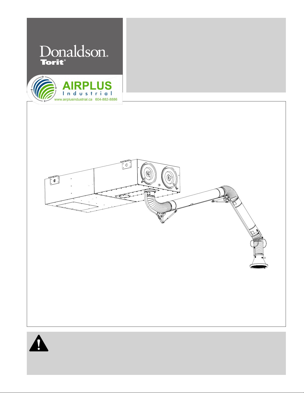
Donaldson Torit AIRPLUS Trunk 2000 T-2000 User manual

This is the safety alert symbol. It is used to alert you to potential personal injury hazards.
Obey all safety messages that follow this symbol to avoid possible injury or death.
This manual is property of the owner. Leave with the unit when set-up and start-up are complete. Donaldson Company reserves the right to
change design and specifications without prior notice.
Illustrations are for reference only as actual product may vary.
Trunk 2000™
T-2000
Installation and Operation Manual
Installation, Operation, and Service Information
IOM 4078300 (ENG)
Revision 7
English
Master Language

Donaldson Company, Inc.
Process owners/operators have important responsibilities relating to combustible hazards.
Process owners/operators must determine whether their process creates combustible dust,
fume, or mist. If combustible dust, fume, or mist is generated, process owners/operators should at a
minimum:
• Comply with all applicable codes and standards. Among other considerations, current NFPA standards
require owners/operators whose processes involve potentially combustible materials to have a current
Hazard Analysis, which can serve as the foundation for their process hazard mitigation strategies.
• Prevent all ignition sources from entering any dust collection equipment.
• Design, select, and implement fire and explosion mitigation, suppression, and isolation strategies that
are appropriate for the risks associated with their application.
• Develop and implement maintenance work practices to maintain a safe operating environment, ensuring
that combustible dust, fume, or mist does not accumulate within the plant.
Donaldson recommends process owners/operators consult with experts to insure each of these
responsibilities are met.
As a manufacturer and supplier of Industrial Filtration Products, Donaldson can assist process owners/
operators in the selection of filtration technologies. However, process owners/operators retain all
responsibility for the suitability of fire and explosion hazard mitigation, suppression, and isolation strategies.
Donaldson assumes no responsibility or liability for the suitability of any fire and/or explosion mitigation
strategy, or any items incorporated into a collector as part of an owner/operators hazard mitigation strategy.
Improper operation of a dust control system may contribute to conditions in the work area or facility that
could result in severe personal injury and product or property damage. Check that all collection equipment is
properly selected and sized for the intended use.
DO NOT operate this equipment until you have read and understand the instruction warnings in the
Installation and Operations Manual. For a replacement manual, contact Donaldson Torit.
This manual contains specific precautionary statements relative to worker safety. Read thoroughly and comply
as directed. Discuss the use and application of this equipment with a Donaldson Torit representative. Instruct all
personnel on safe use and maintenance procedures.
Model Number _____________________________ Serial Number ______________________________
Ship Date _________________________________ Installation Date _____________________________
Customer Name _______________________________________________________________________
Address _____________________________________________________________________________
____________________________________________________________________________________
Filter Type ____________________________________________________________________________
Accessories __________________________________________________________________________
Other________________________________________________________________________________
Data Sheet

DANGER indicates a hazardous situation which, if not avoided, will result
in death or serious injury.
WARNING indicates a hazardous situation which, if not avoided, could
result in death or serious injury.
CAUTION, used with the safety alert symbol, indicates a hazardous
situation which, if not avoided, could result in minor or moderate injury.
NOTICE is used to address practices not related to personal injury that
may result in damage to equipment.
Trunk 2000,T-2000
i
Magnehelic®and Photohelic®are registered trademarks of Dwyer Instruments, Inc.
Contents
Description................................................................................1
Purpose and Intended Use ....................................................1
Rating and Specification Information...................................2
Operation...................................................................................3
Inspection on Arrival...............................................................4
Installation Codes and Procedures ......................................4
Installation.................................................................................4
Foundations or Support Framing .......................................5
Collector Location................................................................5
Site Selection .......................................................................5
Rigging Instructions.................................................................5
Hoisting Information ............................................................5
Standard Equipment................................................................6
Compressed Air Installation...............................................7
Electrical Wiring...................................................................7
Solid-State Timer Installation.................................................9
Preliminary Start-Up Check .................................................11
Maintenance Information.....................................................12
Operational Checklist ........................................................12
Filter Removal and Installation.........................................12
Dust Disposal ......................................................................14
Split Taper™ Bushing Mounting Instructions ...............15
Optional Equipment................................................................16
Hopper Assembly ...............................................................16
Magnehelic®Gauge .........................................................17
Photohelic®Gauge ............................................................19
Delta P Control....................................................................21
Delta P Plus Control ..........................................................22
Sprinkler...............................................................................23
Troubleshooting......................................................................24

1
Donaldson Company, Inc.
Combustible materials such as buffing lint, paper, wood, metal dusts, weld fume, or flammable
coolants or solvents represent potential fire and/or explosion hazards. Use special care when
selecting, installing, and operating all dust, fume, or mist collection equipment when such combustible
materials may be present in order to protect workers and property from serious injury or damage due to a
fire and/or explosion.
Consult and comply with all National and Local Codes related to fire and/or explosion properties of
combustible materials when determining the location and operation of all dust, fume, or mist collection
equipment.
Standard Donaldson Torit equipment is not equipped with fire extinguishing or explosion protection systems.
Description
The Torit Trunk 2000 is used to filter weld fume, dust,
and particulate from plant sources and to recirculate
clean air back to the workplace. Ceiling-hung or wall-
supported, the compact size, coupled with large volume
air handling capabilities allow this unit to be placed in
a wide variety of sites previously inaccessible to high
efficiency dust collectors.
Torit Ultra-Web®FR flame retardant filter cartridges are
the heart of the Torit T-2000. These elements, which are
an example of Donaldson Company's state-of-the-art
filtration technology, help ensure that only clean air is
returned to the plant environment.
Purpose and Intended Use
Misuse or modification may result
in severe personal injury and/or
property damage.
Do not misuse or modify.
The T-2000, designed for source collection of weld fume,
is capable of handling 890 cfm. It provides one or two
extraction arms for fume collection.
The T-2000 is designed to capture fume generated from
moderate to heavy welding applications.

Trunk 2000,T-2000
2
All Collectors*:
Compressed air, maximum psig........90 psig 1.11 scf/pulse
Power and controls ................................................... 115 VAC
Rating and Specification Information
Front View Typical Side View

3
Donaldson Company, Inc.
Operation
Dust or fume enters through the extraction arm(s), and is
collected on the outside surfaces of the filter elements.
The clean, filtered air passes through the center of the
filter elements, into the blower, through the silencer
sections of the cabinet, and exits through the clean-air
outlet.
Filter cleaning starts when the blower is turned on. A
solid-state control timer energizes a solenoid valve,
causing the corresponding diaphragm valve to send a
pulse of compressed air through the filter elements (from
the inside outward), removing the dust from the outside
of the filter elements. The dust then falls into the hopper.
At the end of the pulse, the diaphragm valve closes and
the elements are back in normal operation. After a preset
time interval elapses, the timer sequences to the next
valve in the system. This cycle will continue until the
blower fan is turned OFF.
Filter Elements
Contaminated
Air Inlet
Clean Air Outlet
Clean Air Plenum Blower Wheel and Motor
Compressed Air Manifold
Compressed Air Supply
(Purge Air)
Diaphragm Cleaning Valve
Normal Operation
Filter Cleaning
Unit Operation

Trunk 2000,T-2000
4
Inspection on Arrival
1. Inspect collector upon delivery.
2. Report any damage to the delivery carrier.
3. Request a written inspection report from the Claims
Inspector to substantiate any damage claim.
4. File claims with the delivery carrier.
5. Compare collector received with description of
product ordered.
6. Report incomplete shipments to the delivery carrier
and your Donaldson Torit representative.
7. Remove crates and shipping straps. Remove loose
components and accessory packages before lifting
collector from truck.
8. Check for hardware that may have loosened during
shipping.
9. Use caution removing temporary covers.
Installation Codes and Procedures
Codes may regulate recirculating
filtered air in your facility.
Consult with the appropriate authorities
having jurisdiction to ensure compliance
with all national and local codes regarding
recirculating filtered air.
Safe and efficient operation of the collector depends on
proper installation.
Authorities with jurisdiction should be consulted
before installing to verify local codes and installation
procedures. In the absence of such codes, install
collector according to the National Electric Code,
NFPA No. 70-latest edition and NFPA 91 (NFPA 654 if
combustible dust is present).
A qualified installation and service agent must complete
installation and service of this equipment.
All shipping materials, including shipping covers, must
be removed from the collector prior to or during collector
installation.
Failure to remove shipping
materials from the collector will
compromise collector performance.
Inspect collector to ensure all hardware is properly
installed and tight prior to operating collector.
Installation
Use proper equipment and adopt
all safety precautions needed for
servicing equipment.
Electrical service or maintenance work must
be performed by a qualified electrician and
comply with all applicable national and local
codes.
Turn power off and lock out electrical
power sources before performing service or
maintenance work.
Do not install in classified hazardous
atmospheres without an enclosure rated for
the application.
Turn compressed air supply OFF, bleed and
lock out lines before performing service or
maintenance work.
Site selection must account for
wind, seismic zone, and other
load conditions when selecting the location for
collectors.
Codes may regulate acceptable locations for
installing dust collectors. Consult with the
appropriate authorities having jurisdiction to
ensure compliance with all national and local
codes regarding dust collector installation.
Collectors must be anchored in a manner
consistent with local code requirements.
Anchors must be sufficient to support dead,
live, seismic, and other anticipated loads.
Consult a qualified engineer for final selection
of anchorage.
Do not set compressed-air
pressure above 100-psig as
component damage can occur.
All compressed air components must be sized
to meet the system requirements of 90-100-psig
supply pressure.
The compressed-air supply must be oil
and moisture free. Contamination in the
compressed air used to clean filters will result
in poor cleaning, cleaning valve failure, or poor
collector performance.
Purge compressed air lines to remove
debris before connecting to the collector’s
compressed air manifold.

5
Donaldson Company, Inc.
The collector is suitable for indoor installations.
Reference the Rating and Specification Information.
Collector Location
Donaldson Torit equipment is not
designed to support site installed
ducts, interconnecting piping, or electrical
services. All ducts, piping, or electrical
services must be adequately supported to
prevent severe personal injury and/or property
damage.
When hazardous conditions or materials are
present, consult with local authorities for the
proper location of the collector.
Dust collection equipment may
reach peak sound pressure
levels above 80 dB (A). Noise levels should be
considered when selecting collector location.
Locate the collector to ensure easy access to electrical
and compressed air connections, to simplify solids
collection container handling and routine maintenance,
and to ensure the straightest inlet and outlet ducts.
Foundations or Support Framing
Prepare the foundation or support framing in the
selected location. Foundation or support framing must
comply with local code requirements and may require
engineering.
Foundation and support framing must be capable of
supporting dead, live, wind, seismic and other applicable
loads. Consult a qualified engineer for final selection of
foundation or support framing.
Site Selection
This collector can be located on a foundation or
structural framing. It can also be suspended or hung
from overhead supports. The supports must be adequate
to carry the live load of the collector and installed to
reduce sway or vibration to the collector.
Provide clearance from heat sources and avoid any
interference with utilities when selecting the location.
Rigging Instructions
Suggested Tools & Equipment
Clevis Pins and Clamps Lifting Slings
Crane or Forklift Pipe Sealant
Drift Pins Pipe Wrenches
Drill and Drill Bits Screwdrivers
End Wrenches Socket Wrenches
Adjustable Wrench Spreader Bars
Torque Wrench (inch/lbs, 9/16-in Socket)
Hoisting Information
Failure to lift the collector
correctly can result in severe
personal injury and/or property damage.
Use appropriate lifting equipment and adopt
all safety precautions needed for moving and
handling the equipment.
A crane or forklift is recommended for
unloading, assembly, and installation of the
collector.
Location must be clear of all obstructions, such
as utility lines or roof overhang.
Use all lifting points provided.
Use clevis connectors, not hooks, on lifting slings.
Use spreader bars to prevent damage to collector’s
casing.
Check the Specification Control drawing for weight and
dimensions of the collector and components to ensure
adequate crane capacity.
Allow only qualified crane or forklift operators to lift the
equipment.
Refer to applicable OSHA regulations and local codes
when using cranes, forklifts, and other lifting equipment.
Lift collector and accessories separately and assemble
after collector is in place.
Use drift pins to align holes in section flanges during
assembly.

Trunk 2000,T-2000
6
Standard Equipment
Improper mounting of an
extraction arm may result in
personal injury. Follow all installation directions
carefully.
1. The T-2000 collector is shipped assembled from the
factory, except for the trunks, which are attached
after the dust collector has been placed. Typically
the Trunk 2000 is suspended from the ceiling;
however, it can be supported by other means, as long
as they are appropriate for the alternate location.
Collector Suspension shows the recommended
method of suspending the Trunk 2000.
2. After the collector has been placed, level by
adjusting the hangers at each corner.
3. Fasten the extraction arms shown in Extraction Arm
Installation and in the Extraction Arm Installation and
Operation Manual.
5/8-in threaded rod,
flat washers and nuts
(typical)
Collector Suspension
Both the 12V and 115V power to the collector are
supplied from the Torit control box. The control box can
be mounted where it is convenient to the user.
When final light wiring
connections are made at the
collector, allow enough slack for free rotation
and motion of the trunk.
The 115 VAC timer in the control box controls the
solenoid valves. Total power requirement of the control
box is 130 watts, including the two 65-watt halogen
lights, one in each Extraction Arm hood.
Each Trunk 2000 collector is equipped with two 115 VAC
solenoid valves that control the pulse cleaning valves.
The DIN connector of the solenoid valve has two power
leads and a ground connection.
The 6.5-ft, 10-ft and 13-ft extraction arms have a 12V,
65-watt halogen light located in each hood.
Solenoid Valve
manifold
solenoid
valve
diaphragm valve
Extraction Arm
Inlet Panel
Extraction Arm
Swivel Base
Extraction Arm
Extraction Arm Installation
(arm may vary from drawing)

7
Donaldson Company, Inc.
1. Remove the plastic pipe plug from the collector’s air
manifold and connect the compressed-air supply
lines. Use thread-sealing tape or pipe sealant on all
compressed-air connections.
2. Install a customer-supplied shut-off valve, bleed-
type regulator with gauge, filter, and automatic
condensate valve in the compressed-air supply line.
3. Set compressed-air supply to 90-psig. The pulse-
cleaning controls are factory set to clean one or
more filters every 10-seconds during a cleaning
cycle.
Electrical Wiring
Electrical installation, service,
or maintenance work must
be performed by a qualified electrician and
comply with all applicable national and local
codes.
Turn power off and lock out electrical
power sources before performing service or
maintenance work.
Do not install in classified hazardous
atmospheres without an enclosure rated for
the application.
All electrical wiring and connections, including electrical
grounding, should be made in accordance with the
National Electric Code (NFPA No. 70-latest edition).
Check local ordinances for additional requirements that
apply.
The appropriate wiring schematic and electrical rating
must be used. See collector’s rating plate for required
voltage.
An electric disconnect switch having adequate amp
capacity shall be installed in accordance with Part IX,
Article 430 of the National Electrical Code (NFPA No.
70-latest edition). Check collector’s rating plate for
voltage and amperage ratings.
Refer to the wiring diagram for the number of wires
required for main power wiring and remote wiring.
Compressed Air Installation
Turn compressed air supply OFF,
bleed and lock out lines before
performing service or maintenance work.
A safety exhaust valve should be used to
isolate the compressed air supply. The safety
exhaust valve should completely exhaust
pressure in the collector manifolds when
closed, should be capable of being interlocked
with fire or explosion mitigation equipment
and should include provisions to allow closed-
position locking.
Do not set compressed-air
pressure above 100-psig as
component damage can occur.
All compressed air components must be sized
to meet the system requirements of 90-100-psig
supply pressure.
The compressed-air supply must be oil
and moisture free. Contamination in the
compressed air used to clean filters will result
in poor cleaning, cleaning valve failure, or poor
collector performance.
Purge compressed-air lines to remove
debris before connecting to the collector’s
compressed-air manifold.

Trunk 2000,T-2000
8
*customer supplied
**extraction arm may vary from drawing
support rods*
1-in NPT compressed-air
connection
(both sides)
Trunk 2000
optional hopper*
extraction arm**
Magnehelic Gauge*
power supply disconnect
switch*
incoming power supply*
blower motor
starter*
optional pulse
control switch
(1TGS)*
solid-state
timer
air
regulator*
bleed-type
air filter*
safety exhaust valve*
automatic condensate valve*
air supply line*
access cover
panel*
Turn power off and lock out
electrical power sources.
Turn compressed air supply OFF, bleed
and lock out lines before performing
service or maintenance work.
Compressed Air Installation

9
Donaldson Company, Inc.
Mount the Trunk 2000 control box(es) and fan starter
switch(es) in a safe, convenient location. Install conduit
and wire up to the collector(s). The disconnect fuses,
magnetic fan starter, and optional control switch 1TGS
are to be supplied by others. All electrical apparatus
should be properly sized for the required voltage. The fan
starter should contain a low voltage control circuit.
Use the wiring diagram (and inside the control box)
to connect the blower motor, motor starter, lights,
solid-state control timer, solenoid valves, and the
control switch (or optional Photohelic gauge if used).
In grounded systems, neutral to control box must be
connected to L2 of control box terminal board.
Operating Logic Diagram
Optional Switch 1TGS: Closure of switch 1TGS applies
power to the timer control circuit board, which is in
parallel with the low voltage coil of the fan magnetic
starter. Supplying power initiates the control board's
preset OFF time. At the end of the OFF time, the control
will energize a solenoid to provide the cleaning pulse
for one segment of filter elements, and then step to the
next segment. This cycle continues until the T-2000 fan
starter is turned off or an auxiliary switch (not supplied)
opens, unless an auxiliary control such as a Photohelic
pressure switch is used to control the timer pressure
switch circuit. Make sure that the programming pin on
the control board is located on the correct number of
solenoid valves being used. See Typical Wiring Diagram.
Output N
Output 2
Output 1
Power Input
ON
OFF
ON
OFF
ON
OFF
ON
OFF
Pulse ON-time for all outputs
See Specifications
Adjustable OFF-time
Between two pulses
Solid-State Timer Installation
Electrical installation, service
or maintenance work during
installation must be performed by a qualified
electrician and comply with all applicable
national and local codes.
Turn power off and lock out electrical power
sources before performing installation, service,
or maintenance work.
Do not install in classified hazardous
atmospheres without an enclosure rated for
the application.

Trunk 2000,T-2000
10
Solid-State Timer Typical Wiring Diagram
Off On
IL1
IL2
IL3
1FU
2FU
3FU
T1
T2
T3
IM I O.L.
Fan Starter
IM
Fan
H1 H2 H3 H4
230V
115V
I O.L.
Stop
X2
Start
X1
IM
IM
460V
115V
Control Box
L1 L2
P.S.
Prog.
Pin 1
2
3
1TGS
3
2
1
COM
Not
Used
Timer Board
Solenoid Valves
Junction Box
115V
Power
Supply
110VAC
12VAC
H
H
Trunk MTD Lt.
65W @ 12V
Trunk MTD Lt.
65W @ 12V
Wiring By Others
Wiring By Torit
Input
105-135V/50 -60Hz/1Ph (others, including 220VAC are
available)
Output Solenoids
The load is carried and turned ON and OFF by the 200
watt maximum-load-per-output solid-state switch.
Pulse ON Time
Factory set at 100-milliseconds.
Do not adjust pulse ON time
unless the proper test equipment
is available. Too much or too little ON time can
cause shortened filter life.
Pulse OFF Time
Factory set at 10-seconds, adjustable from 1 to
1.5-second minimum to maximum 60 to 66-second.
Operating Temperature Range
-20° F to 130° F
Transient Voltage Protection
50 kW transient volts for 20-millisecond duration once
every 20 seconds, 1% duty cycle.
Solenoid Valves
115-V at 19.7 watts each
Compressed-Air
Set compressed-air supply at 90-psig.
Do not increase supply pressure
above 100-psig as component
damage can occur.

11
Donaldson Company, Inc.
Instruct all personnel on safe use and maintenance
procedures.
Electrical work during
installation, service or
maintenance must be performed by a qualified
electrician and comply with all applicable
national and local codes.
Turn power off and lock out electrical
power sources before performing service or
maintenance work.
Turn compressed air supply OFF, bleed and
lock out lines before performing service or
maintenance work.
Check that the collector is clear and free of all
debris before starting.
Do not install in classified hazardous
atmospheres without an enclosure rated for
the application.
Optional fans over 600 lbs must be
independently supported.
Preliminary Start-Up Check
1. Check all electrical connections for tightness and
contact.
2. Check for proper rotation as noted on the fan and/or
hopper discharge device housing.
To reverse rotation, single-phase power supply:
Follow manufacturer’s instructions on the motor’s
nameplate.
To reverse rotation, three-phase power supply:
Switch any two leads on the motor junction box.
Do not interchange a power lead
with the ground wire. Severe
personal injury and/or property damage may result.
3. All access panels should be sealed and secure.
6. Check and remove all loose items in or near the inlet
and outlet of the collector.
7. Check that all remote controls and solenoid
enclosures (if applicable) are properly wired and all
service switches are in the OFF position.
8. Check that all optional accessories are installed
properly and secured.
9. Turn power ON at source.
10. Turn the compressed-air supply ON. Adjust pressure
regulator for 90-100 psig.
11. Turn fan motor ON.
Do not look into fan outlet to
determine rotation. View the fan
rotation through the back of the motor.
Check that the exhaust plenum is free of tools
or debris before checking blower/fan rotation.
Stand clear of exhaust to avoid personal injury.
12. Check the operation of the solenoid valves by turning
the pulse control switch ON. The solenoid valves
should open and close continuously at preset ON
and OFF times.

Trunk 2000,T-2000
12
Maintenance Information
Instruct all personnel on safe use and maintenance
procedures.
Use proper equipment and adopt
all safety precautions needed for
servicing equipment.
Use appropriate access equipment. The
standard collector is not equipped with access
platforms unless noted on specification
drawings.
Electrical service or maintenance work must
be performed by a qualified electrician and
comply with all applicable national and local
codes.
Turn power off and lock out electrical
power sources before performing service or
maintenance work.
Do not install in classified hazardous
atmospheres without an enclosure rated for
the application.
Turn compressed air supply OFF, bleed and
lock out lines before performing service or
maintenance work.
Do not set compressed-air
pressure above 100-psig as
component damage can occur.
All compressed air components must be sized
to meet the system requirements of 90-100 psig
supply pressure.
The compressed-air supply must be oil
and moisture free. Contamination in the
compressed air used to clean filters will result
in poor cleaning, cleaning valve failure, or poor
collector performance.
Purge compressed air lines to remove
debris before connecting to the collector’s
compressed air manifold.
Filter Removal and Installation
Use proper safety and protective
equipment when removing
contaminants and filters.
Dirty filters may be heavier than they appear.
Use care when removing filters to avoid
personal injury and/or property damage.
Turn power off and lock out electrical
power sources before performing service or
maintenance work.
Turn compressed air supply OFF, bleed and
lock out lines before performing service or
maintenance work.
Do not operate with missing or
damaged filters.
Operational Checklist
1. Monitor the physical condition of the collector and
repair or replace any damaged components.
Routine inspections will minimize downtime and
maintain optimum system performance. This
is particularly important on continuous-duty
applications.
2. Periodically check the compressed air components
and replace compressed air filters.
Drain moisture following the manufacturer’s
instructions. With the compressed air supply ON,
check the cleaning valves, solenoid valves, and
tubing for leaks. Replace as necessary.
3. Monitor pressure drop across filters.
Abnormal changes in pressure drop may indicate a
change in operating conditions and possibly a fault
to be corrected. For example, prolonged lack of
compressed air will cause an excess build-up of dust
on the filters resulting in increased pressure drop.
Cleaning off-line with no flow usually restores the
filters to normal pressure drop.
4. Monitor exhaust.
5. Monitor dust disposal.

13
Donaldson Company, Inc.
Filter Removal
1. Turn power to collector OFF.
2. Remove the filter access covers by turning the knob
counterclockwise.
3. Break the seal between the filter cartridge and the
sealing surface.
4. Slowly rotate the cartridge 1/2-turn to remove dust
that may have accumulated on the top of the filter.
5. Slide the filter out the access port along the
suspension yoke and dispose of properly.
6. Inspect and clean the sealing surface if necessary.
Clean dust from gasket sealing
area to ensure a positive filter
gasket seal.
7. Check for an accumulation of dust in the storage
area and empty as necessary.
suspension yoke
filter cartridge
extraction arm
filter access cover
Filter Removal and Replacement (arm may vary from drawing)
Filter Installation
1. Slide the new filter cartridge onto each suspension
yoke.
Insert the filter, gasket end first.
2. Wipe cover gaskets clean and replace covers.
Tighten securely by hand.
Insepct and replace any covers
with damaged or missing
gaskets. Failture to do so may result in leakage
in the collector.
Tighten access covers securely by hand.
Gaskets must be compressed to seal properly.
3. Turn electrical power and compressed air supply ON
before starting unit.

Trunk 2000,T-2000
14
Dust Disposal
Standard Bottom Unit
1. Open the filter-access covers and remove the filter
cartridges. See Filter Removal and Installation.
2. Remove the dust with a dry sweeper or brush and
dispose of properly.
3. Replace filters and close filter-access covers
securely. See Filter Removal and Installation.
4. Turn electrical power and compressed air supply ON
before starting unit.
Hopper Bottom Unit
1. Open the filter-access covers and remove the filter
cartridges. See Filter Removal and Installation.
2. Sweep or brush hopper walls.
3. Replace filters and close filter-access covers
securely. See Filter Removal and Installation.
4. Remove the dustpans and dispose of dust properly.
Empty and clean the dust pans every other day in
heavy dust-load applications, and every week in
light-to-medium applications.
Full dust pans can weigh up to
45-lbs. Use care when removing.
5. Inspect the gasket for wear that could cause a leak
during operation. Replace if necessary.
6. Clean the baffle with a dry brush or dry putty knife.
7. Inspect the draw latches for breaks, deformities, or
wear and replace as necessary.
8. Reinstall the dust pans.
9. Turn electrical power and compressed air supply ON
before starting unit.

15
Donaldson Company, Inc.
Split Taper™ Bushing Mounting Instructions
Many fans are furnished with split taper bushings for
mounting the impeller to the shaft. When properly
assembled, the bushings grip the hub with a positive
clamping action.
1. Bushel barrel and bore of impeller are tapered to
ensure concentric mounting and a true running
propeller.
2. Capscrews, when tightened, lock bushing in
propeller. Use special plated capscrews and nylock
nuts.
Tighten capscrews gradually and evenly with wrench
similar to mounting an automobile wheel. Rotate a
quarter turn on each capscrew successively until
all capscrews are tight. These capscrews force the
taper bushing into the hub, which in turn compresses
the bushing onto the shaft. This makes a positive
clamping fit. The torque must not exceed the value
specified in the table.
Impeller Assembly Removal
1. Remove all capscrews from impeller and hub
assembly.
2. Insert capscrews into the threaded holes in the
bushing flange.
3. Tighten each bolt in quarter of a turn increments to
push the impeller off the bushing. This forces the
bushing loose from the propeller hub and releases
the compression so that the entire assembly will slide
from the shaft.
4. Pull the bushing off the shaft.
Note: If the assembly has been in place sometime
it may be necessary to use a wheel puller to remove
the bushing. Never use a wheel puller on the
impeller.
Split Taper
Bushing
C
A
EDB
A. External key, except G, H and Idler Bushings
B. Bushing barrel and Product bore are tapered
C. Bushing cap screws
D. Bushing barrel is split (except idler bushings)
E. Removal holes are threaded, installation holes are not
Hub of blower wheel
or pulley
Split Taper Bushing Installation
Bushing No. Bolt Size Torque Ft-Lbs
QT/QH/L/H 1/4-20 7-1/2
3. Bushing is split so that when the locking capscrews
force bushing into tapered bore, the bushing grips
the shaft with a positive clamping fit. This will
withstand vibration and heavy loads without being
loosened.
4. Impeller and bushing assembly is keyed to the shaft
and held in place by compression, which adds
driving strength.
Note: Before assembly, ensure shaft and
keyway are clean and smooth. Check key size
with both shaft and bushing keyway.
5. To assemble, insert the capscrews through the
clearance holes in the bushing and install bushing
loosely into the impeller. Do not press or drive. Start
capscrews by hand, turning them just enough to
engage threads in the nylock nut. Do not use a
wrench at this time. The bushing should be loose
enough in the propeller to move freely. Slide impeller
and bushing assembly onto shaft, allowing adequate
clearance for shaft end play to prevent friction. Fit
key into keyway. Do not force impeller and bushing
onto shaft. If it does not go on easily, check shaft,
bushing, and key sizes once again.
Do not attempt to pull bushing flange flush
with hub end. There should
be a clearance which varies
approximately 3/16-in to 1/4-in
with the busing size when tightened. This is
not a locating dimension. Browning®is a registered trademark and Split Taper™is a tradename
of Emerson Power Transmission Manufacturing, L.P.

Trunk 2000,T-2000
16
Hopper Assembly
Optional Equipment
Hopper Assembly
2. Remove the protective shipping cover from the
bottom of the T-2000 dirty-air plenum.
3. Remove the hopper from packaging.
4. Apply 1/4-in diameter, rope-type sealant to the
hopper flange.
5. Using appropriate lifting equipment, lift the hopper
into position under the unit and secure with thirty-
six 1/4-20 UNC x 3/4-in thread-forming screws
supplied. Remove the two round covers to install
the extraction arms to the unit. See Extraction Arm
Installation and Operation Manual for instructions.
Do not over tighten thread-
forming screws.
4. Remove lifting equipment.
1/4-in diameter
rope-type sealant
1/4-20 UNC x 3/4-in
thread-forming bolts
neoprene gasket
dust pan
Failure to lift the collector
correctly can result in severe
personal injury and/or property damage.
Use appropriate lifting equipment and adopt
all safety precautions needed for moving and
handling the equipment.
A crane or forklift is recommended for
unloading, assembly, and installation of the
collector.
Location must be clear of all obstructions, such
as utility lines or roof overhang.

17
Donaldson Company, Inc.
1/8-in NPT x 90°
male elbow
clean-air plenum pressure
tap location 1/8-in NPT adapter
1/8-in NPT adapter
plenum tap location
3/8-in flat washer
1/8-in NPT coupling
mounting bracket
#6-32 x 1/4-in mounting screws
support structure
mounting surface
Magnehelic gauge
high-pressure port
low-pressure port
two, 1/8-in NPT
adapters
plastic tubing
two, 1/8-in NPT pipe plugs
two, self-drilling screws
1/8-in NPT x 90° male elbow
dirty-air plenum pressure tap location
3/8-in flat washer
1/8-in NPT adapter
1/8-in NPT x 90° elbow
static pressure tee
Magnehelic Gauge Assembly
Magnehelic®Gauge
The Magnehelic is a differential pressure gauge used
to measure the pressure difference between the clean-
air and dirty-air plenums and provides a visual display
of filter change requirements. The high-pressure tap is
located in the dirty-air plenum and the low-pressure tap
is located in the clean-air plenum.
1. Choose a convenient, accessible location on or near
the collector for mounting that provides the best
visual advantage.
2. Plug the pressure ports on the back of the gauge
using two, 1/8-in NPT pipe plugs supplied. Install two,
1/8-in NPT male adapters supplied with the gauge
into the high- and low-pressure ports on the side of
the gauges.
3. Attach the mounting bracket using three, #6-32 x 1/4-
in screws supplied.
4. Mount the gauge and bracket assembly to the
supporting structure using two, self-drilling screws.
5. Thirty-five feet of plastic tubing is supplied and must
be cut in two sections. Connect one section of tubing
from the gauge’s high-pressure port to the pressure
fitting located in the dirty-air plenum. Connect
remaining tubing from the gauge’s low-pressure
port to the fitting in the clean-air plenum. Additional
tubing can be ordered from your representative.
6. Zero and maintain the gauge as directed in the
manufacturer’s Operating and Maintenance
Instructions provided.
Table of contents
Other Donaldson Industrial Equipment manuals

Donaldson
Donaldson BOFA AD 350 User manual

Donaldson
Donaldson Ultra-Filter DF 0035 User manual

Donaldson
Donaldson X900133 User manual

Donaldson
Donaldson BOFA AD 1000 iQ User manual

Donaldson
Donaldson A119 Technical specifications

Donaldson
Donaldson Torit RVS-5 User manual

Donaldson
Donaldson Torit MediaFilter Horizontal Series User manual