Omnio AG, Bächlistrasse 326, CH-8426 Lufingen 3301000_Manual_ea.doc
Tel. +41 44 876 00 41, Fax +41 44 876 05 29, 03/11/2008
E-Mail info@omnio.ch, Internet www.omnio.ch
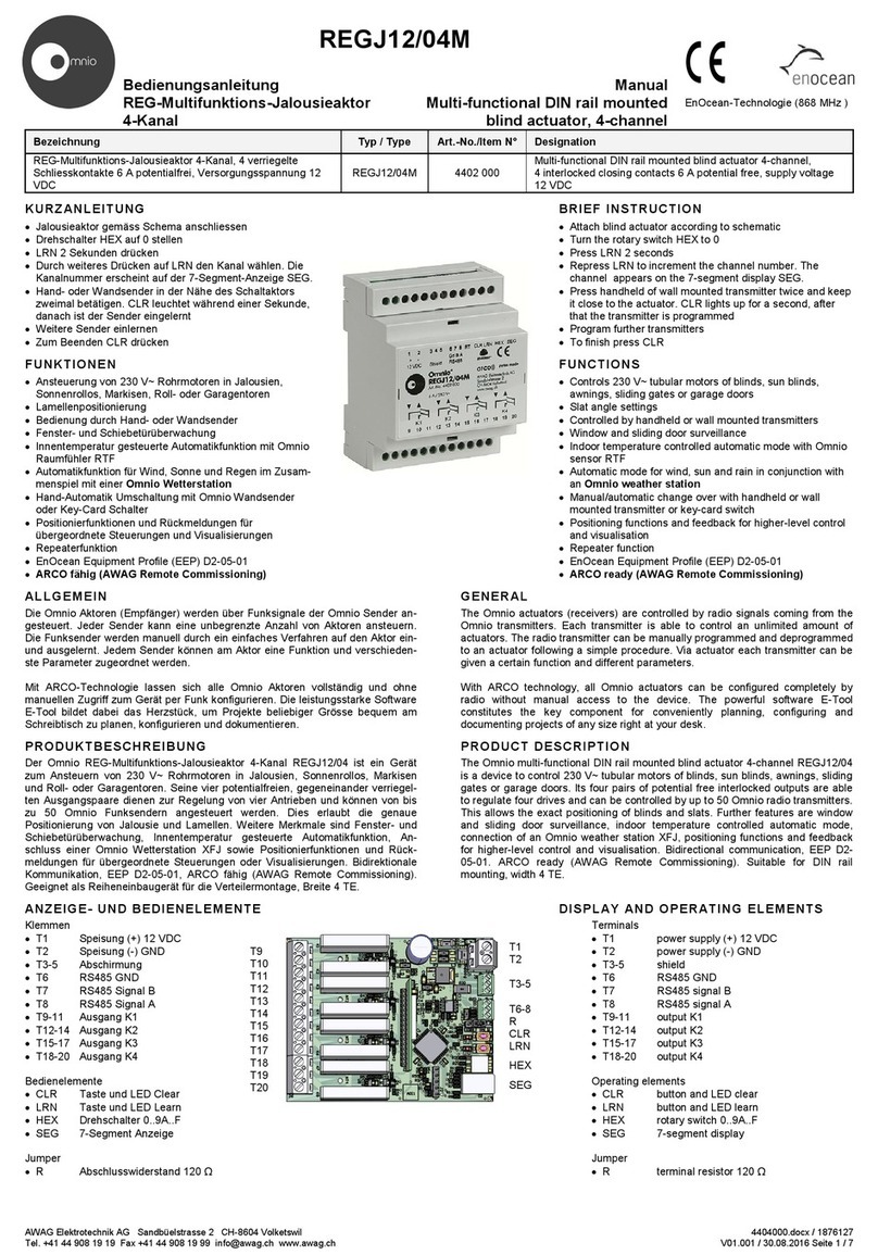
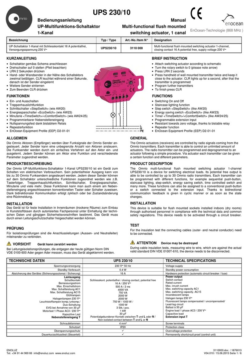
Learning in and unlearning of radio transmitters
Learning mode:
Keep the LRN button pushed. After 1 second, the learning mode becomes active, indicated visually by the flashing CLR-LED and the connected devices. If
you push the LRN button immediately or if no button of a Ratio® radio transmitter is pushed for 30 seconds, the learning mode will be quit automatically.
Programming Ratio® radio senders in Learning mode:
By pressing a Ratio® radio sender key or the programming key of a Ratio® radio sensor (windows contact), the Ratio® switch actuator is allocated on the
appropriate channel. The sender allocation is confirmed when the blinking stops for 4 seconds. Afterwards, the blinking starts again and up to 30 additional
Ratio® radio senders/sensors may be programmed. Note that the rocker A (the left one) will be fix allocated on channel K1, the Rocker B (the right one) will
be fix allocated on channel K2.
If the Ratio® UP actuator is in the learning mode, a transmitter must not be farther away than 5m from the Ratio® UP actuator, since in this mode the
Ratio® UP actuator is working with a range limited to 5m.
Selective unlearning of transmitters:
Individually learned in Ratio® radio transmitters/sensors can be unlearned selectively. To this end, the Ratio® UP actuator has to be switched to the
learning mode (push LRN button for 1 second). If an already learned in button of a Ratio® radio transmitter/sensor is now pushed, this button will be
unlearned immediately. This is indicated by the fact the CLR-LED stops flashing for 4 seconds. Then the flashing starts again and you can learn in or
unlearn further transmitters. If you push the LRN button immediately or if no button of a Ratio® radio transmitter is pushed for 30 seconds, the
learning/clearing mode will be quit automatically.
Unlearning all learned in transmitters:
Keep the CLR button pushed. After approx. 3 seconds all learned in Ratio® radio transmitters / sensors will be cleared from the memory and after another 2
seconds the program automatically switches over to the learning mode.
Function setting:
The functionality of the Relais from the Ratio® switch actuator can be changed. That can be achieved by pressing the rocker 4 times (On or Off) of the
learned in Ratio® radio wall transmitter according the table bellow. The breaks between pressing the rocker should not exeed 0,5 secondes.
Note: For activate or deactivate of parameters, there are no actions at the Ratio® switch actuator itself needed.
Selecting and deselecting parameters:
To select one of the parameters, you first have to switch to the parameterization mode (no. 8). Then you can select all parameters starting with no. 1. Every
selection of a parameter is indicated by a relay pulse of 1s duration and every deselection by a relay pulse of 500ms duration. Send the key sequence (no.
8) again to quit the parameterization mode again.
Example: Selecting the switch-off delay 5 minutes:
1. Select the parameterization mode with the key sequence
1-0-0-0 for parameter no. 8. If the parameterization mode
is active, a switching of the relay should not be possible
any more.
2. Select parameter no.13 with the key sequence 1-1-0-1.
3. Quite the parameterization mode with key sequence 1-0-0-0
for parameter no. 8.
Now the Ratio® UP actuator is enabled with the function
switch-off delay 5 minutes.
0 means the Off side of a rocker of the radio wall transmitter, 1 means the On side of a rocker of the radio wall transmitter.
Legal requirements / old devices
The transmitters may not be used in connection with devices that are employed, directly or indirectly, for health- or life-saving purposes or if their operation
may cause hazards to human beings, animals or property. Do not leave packaging material lying around carelessly. Plastic foils/bags, etc. may be
hazardous toys for children.
These operating instructions are part of the device and part of our warranty terms. They have to be handed over to the customer. The technical
specifications of the device may be changed without prior notice.
Do not throw old devices into the domestic garbage can. The device contains electrical components that have to be disposed off as electronic waste. The
case is made of reusable plastic material.
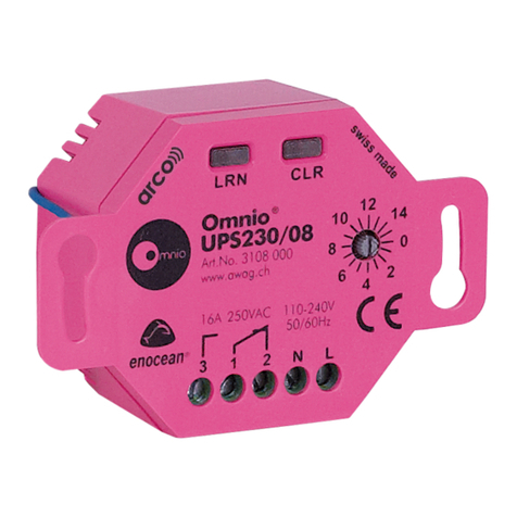
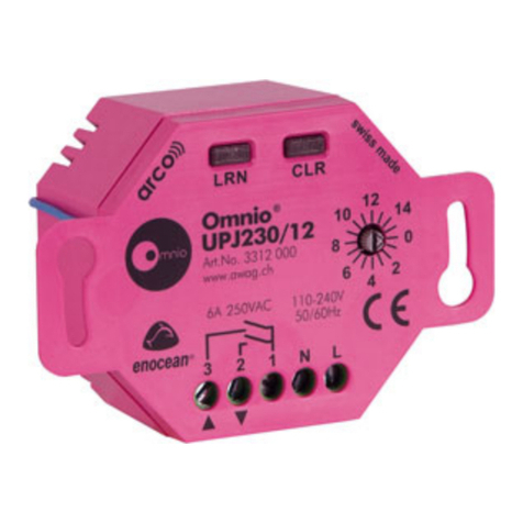
Wiring diagram Designation Type Article number
L
N
1
3
2
CLRLRN
UPJ230/01
868MHz
enocean
M
Ratio®-UP blinds actuator single 230VAC/6A,
Main supply 230VAC UPJ230/01 3301000
Nr.
Tastabfolge
eines
Funksender
Default
wert
Parameterbeschreibung
0 0 0 0 0 - Reset to default
1 0 0 0 1 0 Key sequence ON/OFF
2 0 0 1 0 0 Reverse outlet (UP=DN / DN=UP)
3 0 0 1 1 0 Switchsignal will be inverted
4 0 1 0 0 0 Nicht definiert
5 0 1 1 0 Nicht definiert
6 0 1 1 0 1 Solar sensor switches outlet on (SET)
7 0 1 1 1 1 Solar sensor switches outlet off (CLR)
8 1 0 0 0 - Parameterization mode ON/OFF
9 1 0 0 1 1 Timer 0 seconds (inactive)
10 1 0 1 0 0 Switch-off delay 6 seconds
11 1 0 1 1 0 Switch-off delay 1 minutes
12 1 1 0 0 0 Switch-off delay 2,5 minutes
13 1 1 0 1 0 Switch-off delay 5 minutes
14 1 1 1 0 0 Switch-off delay 10 minutes
15 1 1 1 1 0 Switch-off delay 20 minutes
On / Down(1)
