2 Safety
DANGER
Danger to life through electric current
Works on electrical systems must only be
carried out by skilled electricians.
• Before starting work on electrical systems
and equipment, establish a zero‑potential
condition and ensure this condition while
carrying out the work.
2.1 Intended use
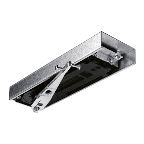
The catching device is used to keep open fire and
smoke protection closures. Fire and smoke protection
closures must meet the building regulation
requirements ‘’self‑locking’’. The slide rail system
ensures the correct order when closing 2‑winged
doors. The electromechanical locking device is no
substitution for a door stop. The locking device is
released manually or via an external RMZ.
2.2 Foreseeable misuse
Do not control any further alarm systems with the
fire detector of the catching device, e.g. transmission
device for fire alarms.
2.3 Limitation of liability
The manufacturer does not assume liability for
damages in the following events:
• Nonobservance of this instruction.
• A deviating application of the intended use.
• The assignment of insufficiently skilled staff.
• Unauthorized modifications.
• Technical alterations.
• The use of spare parts which are not authorized.
2.4 Prerequisites for the
operation of catching devices
The use of catching devices is subject to special
regulations by reason of official admission standards.
These regulations refer in particular to the inspection,
the continuing surveillance and the maintenance.
Follow the details from the data sheet about the use
of catching devices.
If the lower surface of the cover on one or both sides
of the door is more than 1 m above the lintel bottom
edge, an additional cover smoke detector must be
mounted on each side of the door and must be
connected with the RMZ. Measure the distance up to
the smoke‑impermeable ceiling. A separate
verification of suitability is required for the respective
fire / smoke protection door.
Do not control any further alarm systems with the
fire detector of the catching device, e.g. transmission
device for fire alarms.
1
RMZ
2
EMF
3
Cover smoke detector
4
Manual release button for catching devices
(optional). The manual release button must not
be covered by the locked door.
2.5 Requirements of the electrical
installation by the customer
A circuit breaker B‑10A/B‑16A must be present in the
supply circuit. The circuit breaker simultaneously
serves as disconnect device to switch the RMZ to
zero‑potential. The transverse section of the mains
supply line must only be a max. 3 x 1.5 mm² (NYM).
3 Product description
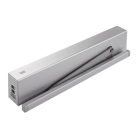
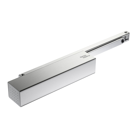
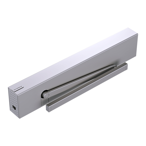
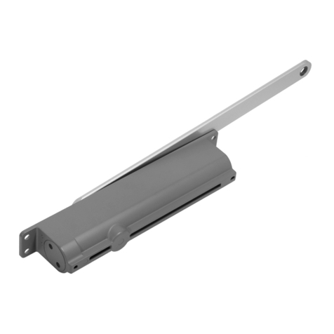
The GSR‑EMR XEA BG comprises the following
components:
• Slide rail system with sequential locking control
• Built‑in electromechanical locking device
• Smoke detection panel
The GSR‑EMR XEA BG is intended for the mounting
into the opposite hinge side. The GSR‑EMR XEA BG is
suitable for DIN‑L and DIN‑R doors.
The sliding rail system GSR‑EMR XEA BG is suitable
for door widths of 1800‑2500 mm.
3.1 RMZ
The RMZ supplies the connected electromechanical
locking device with 24‑V‑DC voltage. In the event of
an alarm or a power cut, the RMZ switches to zero‑
potential (tripping) and the door closes. The new
arming takes place either through a manual or
automatic reset. Optional cover smoke detector RMZ
and manual release buttons HT may be connected to
the RMZ. 2 LEDs show the current operating status.
The configuration of the RMZ happens through the
DIP switch.
3.1.1 DIP switch on the RMZ
The functions of the RMZ are set via the DIP switch.
Changes are only accepted after pressing the reset
button (settings see chapter 5.1).
3GSR-EMR XEA BG 2018-12
dormakaba Mounting instructions
WN 059399 45532
Safety
