manuals.online logo
Brands
  1. Home
  2. •
  3. Brands
  4. •
  5. Dossena
  6. •
  7. Relay
  8. •
  9. Dossena DER3B-MED Series User manual

Dossena DER3B-MED Series User manual

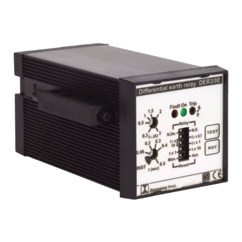
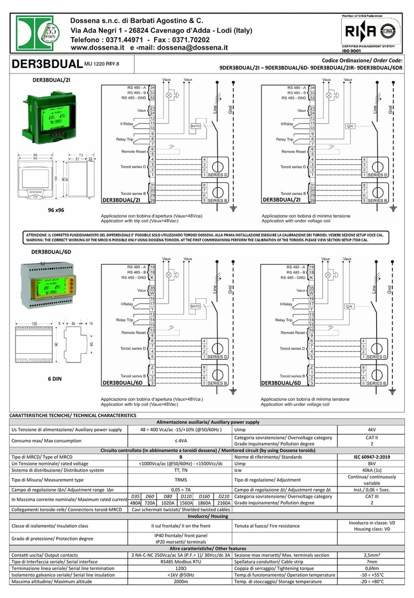
DER3B-MED Codice Ordinazione/ Order Code:
9DER3BMED/2I – 9DER3BMED/6D- DER3BMED/2IR- DER3BMED/6DR
Generalità: I relè differenziali Dossena della serie DER3B-MED possono essere impiegati su reti BT in corrente continua (un polo a terra), alternata (TT,T )
o mista. In particolar modo, la serie è consigliata per la protezione di Inverter, UPS, macchine utensili, convertitori di frequenza, impianti fotovoltaici, mezzi di
produzione nei cantieri, ascensori, torni, frese, apparecchiature elettromedicali quali RM , TAC ecc, dal momento che nel settore industriale e terziario, sono
sempre più diffusi dispositivi che generano correnti disperse di tipo continuo o miste, che i normali relè differenziali in classe A-AC non rilevano. Disponibili
versioni modulari (6DI ) o per montaggio da fronte quadro (96X96X51mm). Per brevità, all'interno del documento ci si riferirà al DER3B-MED semplicemente
come "DER3".
Introduction: The earth differential relays series DER3B-MED could be used in LV network in DC ( ole to ground), AC (TT,TN) or mixed current. In
articular the series is recommended for the use with Inverter, UPS, machine tools, frequency converters, hotovoltaic system, roduction facilities on
construction sites, lifts, lathes, milling machines, electro-medical devices like MRI, C.A.T.etc, since in the industrial and tertiary sectors are becoming more
wides read the devices that generate continuous or mixed current dis ersion, which the normal leakage relays, in class A-AC don't detect. Available
versions: modular (6DIN) or flush mounting anel (96x96x51mm). In the all document the name "DER3" will be used in lace of DER3B-MED for brevity.
Precauzioni di sicurezza: Tutte le operazioni di installazione e manutenzione devono essere eseguite da personale qualificato in assenza di tensione ed in
totale regime di sicurezza elettrica, nel rispetto delle normative vigenti.
Safety Precaution: The installation and connection o erations, must be erformed by following normal safety rocedures. Make the connections with the
ower su ly cut off.
NOTA: il relè differenziale in classe B serie DER3B-MED deve essere SEMPRE installato insieme ai trasduttori toroidali serie B e D per un corretto
funzionamento (DER3B-MED + TRASDUTTORE SERIE D + TRASDUTTORE SERIE B).
For a right working of the differential relay in class B series DER3B-MED is necessary ALWAYS install the toroidal transducers B and D series (DER3B-
MED + TRANSDUCER SERIES D + TRASDUCER SERIES B).
CONSIGLI DI INSTALLAZIONE/ INSTALLATION SUGGESTIONS
1) Prima di alimentare l’apparecchiatura DER3 verificare di aver eseguito correttamente tutti i collegamenti necessari
2) La sezione dei conduttori deve essere tale che la resistenza totale delle connessioni DER3↔trasduttori (andata+ritorno) non superi 1Ω
3) Ridurre al minimo la distanza dei collegamenti tra DER3 e trasduttori (separare il circuito di misura da quello di prova) tenendoli il più lontano possibile da
cavi di potenza; utilizzare cavi schermati con lo schermo isolato dai conduttori interni e connesso a terra in un solo punto.
4) Alla prima messa in ser izio effettuare l'operazione di calibrazione deI toroidi ( edi sezione setup oce CAL).
1) Before owering the DER3, verifies that all connections have been executed correctly
2) Conductors size has to consider that total resistance of connections between DER3 ↔transducers and vice versa don’t exceed 1Ω
3) Reduce to the minimum the distance between DER3 and transducers, (se arate the measure circuit from test circuit) and kee them away from ower
cable; use shielded wires with insulated conductors and connect to ground in only one oint.
4) At the first commissioning perform the ca ibration of toroids, p ease view section SETUP item CAL.
Pag 1 di 4
Caratteristiche elettriche/ E ectrica characteristics
Tensione di alimentazione
Auxi iary power supp y
48 ÷ 400Vca/ac
(-15/+10%) Uimp 4kV Caratteristica di inter ento con tempo
limite di non inter ento di 0,06s/
Operating characteristic having a
imiting non-actuating time of 0.06s.
Frequenza Vaux
Vaux Frequency 50/60Hz Classe di isolamento
Insu ation c ass
II sul frontale
II on the front
Consumo max
Max consumption ≤ 9VA Tenuta al fuoco
Fire resistance
Involucro in classe V0
Housing class V0
Campo di regolazione IΔn
Adjustment range IΔn 0,03 ÷ 7A Grado di protezione
Protection degree
IP40 frontale/
IP20 morsetti
IP40 front anel/
IP20 terminals
Campo di regolazione Δt
Adjustment range Δt
Ist./ 0,06 ÷ 10Sec. Sezione max morsetti
Max. termina s section 2,5mm2
Tipo di regolazione
Adjustment
Continua
Constant
Spellatura conduttori
Cab e strip 7mm Norme di riferimento
Standards
CEI E 60947-2:2007 all. M ed. 8
IEC 60947-2:2006 annex M ed.4
Contatti uscita
Output contacts
n°2 A-C- C 250Vca
5A per P.F.= 1
n° 2 NO-C-NC 250Vac
5A for P.F.= 1
Coppia di serraggio
Tightening torque 0,6 m
Tipo di Misura
Measurement type TRMS
Collegamenti trasduttore-
relè/ Connections
transducer-re ay
Schermati
Shielded
Tipo di rete da controllare
Type of network to contro 50Hz ≤1000Vca/ac Temp.di funzionamento
Operation temperature -10 ÷ +55°C
Sistema di distribuzione
Distribution system
TT, T (CA/AC), CC/DC
(neutro a terra o sistemi
misti/ ( ole to ground or
mixed systems)
Massima altitudine/
Maximum a titude 2000m
Classificazione
C assification BTemp. di stoccaggio
Storage temperature -20 ÷ +80°C
Configurazione/ Setup
Display azzurro/
b ue disp ay
Funzione dei pulsanti (nella ersione 6D i tasti sono sulla destra)/
Keys function (for 6Din version the keys are on the right side)
Note: in caso di Allarme/Trip, durante
l'operazione di SETUP, la serie DER3
interverrà secondo le impostazioni del
precedente SETUP. Per visualizzare la
causa di Allarme/Trip, uscire dal SETUP.
Note: in case of Alarm/Tri , during
SETUP o erations, DER3 will o erate
according to revious SETUP. To dis lay
the cause of Alarm/Tri , exit from SETUP.
CAL= pulsante per la calibrazione dei trasduttori. Tale operazione va eseguita in totale assenza di corrente
differenziale. Premere due volte velocemente questo tasto, quindi il display si colora di viola e il dispositivo
esegue la calibrazione automaticamente. Questa operazione è assolutamente necessaria per la messa in
servizio dello strumento. Se la calibrazione va a buon fine il display ritorna blu. on è possibile effettuare
l'operazione di calibrazione in presenza di allarmi rilevati dal dispositivo (ALA – TRIP- TORO).
CAL= button for transducers calibration. This o eration must be erfomed in total absence of differential
current dis ersion. Pushing quickly for two times this button and the dis lay a ears violet and the device
make the calibration automatically. This o eration is absolutely necessary for commissioning of the instrument.
If calibration will be good the dis lay back to blue. It's not ossible make calibration if an alarm is detected (ALA
– TRIP - TORO).
SET= tasto multifunzione:
1- premere per almeno 3 secondi per entrare nel SET UP (display apparirà azzurro)
2- premere per visualizzare i parametri in modo ciclico
3- premere per almeno 3 secondi per uscire dal SET UP, salvando i parametri impostati (il display
ritorna verde)
Dopo circa 3 minuti di inattività il DER3 esce automaticamente dal SET UP senza sal are le modifiche.
SET= multifunction button:
1 -push for at east 3 seconds to enter in SET UP (dis lay will be blue)
2- ush to see the arameters in cyclically
3-push for at east 3 seconds to exit from SETUP and save the parameters (dis lay
return green)
After 3 minutes of inactivity the DER3 automatically exits from SETUP without saving modification.
▲▼= premere per modificare il parametro selezionato (apparirà lampeggiante)
ush to modify the selected arameter (it will a ear flashing)
Pag 2 di 4
PREDISPOSIZIONE PARAMETRI/ SET UP PARAMETERS RANGE DEFAULTS
A/T: Funzione del secondo relè. Il secondo relè può essere impostato come relè di allarme o come secondo relè
di TRIP/ Function of second relay. The second relay can be set as alarm relay or as second relay of TRIP
A - il relè cambia di stato al superamento della soglia di allarme impostata/ The relay changes state when the
alarm threshold set overcome
T - il relè cambia di stato contemporaneamente al relè di TRIP (la bobina di apertura deve comunque essere
sempre collegata al relè di TRIP)/ the relay changes state at the same time of TRIP relay (the o ening coil must
be a ways connected to TRIP relay)
Trip “T”/ Allarme “A”
TRIP “T”/ Alarm “A” A
Stato del relè di TRIP*/ State of TRIP alarm *:
Con il simbolo/With the symbol (NDe): il rele è normalmente diseccitato ( .De.) e si eccita quando la ID
supera la Idn/ the relay is normally de-energized (N.De.) and it energizes when ID overcomes IDn
Con il simbolo/ With the symbol (NE): il rele è normalmente eccitato ( .E.) e si diseccita quando la ID
supera la Idn/ the relay is normally energized (N.E.) and it de-energizes when ID overcomes IDn
.De. norm. Diseccitato/
N.De normally de-
energized
.E. norm. Eccitato/
N.E. normally energized
.De.
MAN/AUTO: Stato di funzionamento del RESET: in modalità manuale, a seguito di uno scatto per IΔ>IΔn, la
scritta “SET” diventa “RESET” e permetterà quindi il RESET della condizione di TRIP (solo se IΔ<IΔn)/
O erating state of Reset: The RESET could be setted in manual or automatic mode. In manual mode, after a tri
for IΔ>IΔn, the writing “SET” become “RESET” and allows the “ RESET” from TRIP condition (only if IΔ<IΔn).
“MA ”= Manuale/Manual
“AUTO”=
Automatico/Automatic MA
◄ AL: Soglia di intervento relè di Allarme (% di IΔn): al superamento della soglia impostata interviene il secondo
relè ed il display diventa giallo/rosso lampeggiante/Threshold of Alarm relay (% di IΔn): when set alarm threshold
is exceeded, the second relay changes state and the dis lay is flashing yellow/red.
20 ÷ 80% di IΔn
20 ÷ 80% of IΔn 50%
<R: Valore d'isteresi dei relè A e T: è possibile impostare un valore percentuale d'isteresi per evitare che delle
piccole variazioni della corrente rilevata intorno al valore di IΔn provochino scatti e rilasci ripetuti del relè (in
modalità di RESET AUTO)/ Hysteresis value of relays A and T: it's ossible to set an hysteresis ercentage
value to avoid that continuous variation of current next to value of IΔn could roduce continuously alarm or
TRIP state (in RESET AUTO mode)
30 ÷ 80% delle soglie di
intervento
30 ÷ 80% thresholds of
intervention
80%
KCT= rapporto di trasformazione del trasduttore O VARIARE QUESTO PARAMETRO/ transformation ratio
of transducer DON'T CHANGE THIS PARAMETER -- 0,500K
BA AL= allarme per anomalia della bobina di apertura/ Se impostato su O la continuità della bobina di apertura e
la sua alimentazione sono vigilati costantemente generando allarme in caso di anomalia/ Alarm for anomaly on
o ening coil: if you set to ON, the continuity of o ening coil and its ower are constantly su ervised and
generate alarm in case of malfunction.
O -OFF O
NODE**= Configurazione nodo di rete: assegnare ad ogni singolo DER3 un numero di nodo compreso tra 1 e
247/ Configuration network node: assign to each DER3 a node number between 1 and 247 1 ÷ 247 1
BAUD**= Configurazione velocità seriale/ Serial baudrate configuration 4800/ 9600/ 19200/ 38400 19200
IDn (A)= Soglia della corrente di dispersione nominale: valore al quale la ID provoca l'intervento del relè di TRIP/
Nominal current threshold of intervention: the value at which the IΔ causes the intervention of TRIP relay 0,03 ÷ 7A 0,05A
ΔT= Tempo limite di non intervento (s): ritardo entro il quale una corrente differenziale più elevata di IΔn può fluire
nel DER3 senza provocare l'intervento/ delay during which a residual current more higher than IΔn can flow into
DER3 without cause intervention.
Istantaneo “I ST”/
ritardato: 0,06 ÷ 5Sec.
Instantaneous “I ST”/
delay: 0,06 ÷ 5Sec.
0,060Sec.
* Attenzione: la condizione di .E. (sicurezza positiva) è applicata solo ed esclusivamente al relè di TRIP e non al secondo relè anche se impostato in
configurazione TRIP. L'impostazione della sicurezza positiva esclude la vigilanza continua del circuito della bobina di apertura B.A. e della sua alimentazione.
* Warning: the safety condition N.E, is a lied exclusively to the TRIP relay and not to second relay even it is set in TRIP condition. Setting the ositive
security excludes the ermanent verification of the circuit of o ening coil T.C. and its ower.
** Solo per versioni dotate di uscita seriale RS485/ ** Only for versions equi ed with serial out ut RS485
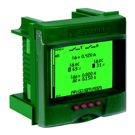
STATO DI NORMALE VIGILANZA/ NORMAL VIGILANCE
Display erde (nella ersione 6Din i tasti sono sulla destra)/
Green disp ay (version 6Din the buttons are on the right)
Misure e parametri/
Measures and parameters
Pag 1
Visualizzazione in vero valore efficace
(TRMS) della dispersione in CA (corrente
alternata) e CC (corrente continua)
presente in impianto.
Dis lay in TRMS of leakage current in AC
(alternative current) and DC (continuous
current) resent in the system.
Pag 2
Visualizzazione in vero valore efficace
(TRMS) del totale della corrente
differenziale dell'impianto e relativo valore
in % della corrente dispersa in CA
(corrente alternata) e CC (corrente
continua).
Dis lay in TRMS of leakage current on
system and relative % value of leakage
current in AC (alternative current) and
DC (continuous current) .
I∆ AC TRMS/ I∆ DC TRMS= correnti di dispersione presenti in
impianto in tempo reale espresse in A o come valore %/ currents
dis ersion resent in the system in TRMS esx ress in A or as %
value
I∆= corrente dispersa in TRMS/ leakage current in TRMS
I∆n= soglia corrente di dispersione impostata/ set current
threshold
∆t= tempo limite di non intervento/ limit time of no-intervention
Istogramma= istogramma istantaneo identificativo della corrente
dispersa in CC (segmento pieno) e CA (segmento a righe
diagonali)/ Instantaneous histogram that identifies leakage current
in DC (full segment) AC (diagonal stripes segment)
AL= visualizzazione grafica della soglia di allarme impostata/
gra hic dis lay of set alarm threshold
►: Premendo questo tasto si sceglie la visualizzazione di Pag 1
(valori in TRMS) o Pag2 (valori in %)/ Push this button to dis lay
Pag1 (value in TRMS) or Pag 2 (% value)
: Premere per variare il contrasto del diplay/Push this button to
adjust the contrast
Pag 3 di 4
TEST: Il test verifica l'intero sistema di protezione differenziale (DER3 + Trasduttori serie B e D + B.A.)
The test checks the com lete differential rotection system (DER3 + Transducers series B and D + T.C.)
DISPLAY E enti/ Events Funzione dei pulsanti/ Keys function
(ROSSO/ Red)
(nella versione 6D i tasti sono sulla destra/
version 6D the buttons are on the right)
Display rosso fisso/ dis lay red
Relè TRIP e II° relè cambiano stato/ TRIP relay and
II° relay change state
lampeggia il segnale di pericolo/ flashing danger
signal
lampeggia la scritta "TRIP"/ flashing "TRIP"
TEST= premere per eseguire il test/ ush test button to
erform the test
RESET= premere RESET per eseguire il riarmo
manuale a seguito del TEST (appare solo se impostato
in modalita manuale “MA ”)/ ress RESET to erform
manual rearmament after the TEST (it a ears only in
manual mode “MAN”).
ALLARMI: tutti riconoscibili dal simbolodi pericolo/ ALARMS: the danger symbol is visible for every alarm
DISPLAY
E enti/ Events
Causa/ Cause
ALA
display lampeggiante giallo/rosso/ flashing yellow/red dis lay
II° relè (relè di allarme) cambia stato/ IInd relay (alarm relay) changes state
lampeggia il segnale di pericolo/ flashing danger signal
lampeggia la scritta ALA/ flashing the written ALA
incremento dell'istogramma/ increasing of histogram
incremento del valore di corrente I∆/ increasing current value I∆
Superamento soglia allarme/ A arm theresho d exceeded:
La I∆ ha superato la soglia di allarme preimpostata
The I∆ has overcome set alarm threshold
BA
display lampeggiante giallo/rosso/ flashing dis lay yellow/red
II° rele cambia stato/ IInd relay change state
lampeggia il segnale di pericolo/ flashing danger signal
lampeggia "BA"/ flashing "BA"
ALLARME B.A./ ALARM BA: Puo essere accaduto che/ It is detected that:
-sia avvenuta una interruzione nell'avvolgimento della B.A.
-Sia avvenuta una disconnessione tra DER3 e B.A.
-Sia venuta a mancare la tensione che a seguito del trip permetterebbe
l'azionamento della B.A.
-the sto winding of T.C.
- the disconnection between DER3 and T.C.,
-the lack of ower su ly voltage that com romise the o eration of T.C.
TRIP
display rosso fisso/ dis lay lighting red
II° rele e rele T cambiano stato./ IInd relay and relay T change state
lampeggia il segnale di pericolo/ flashing danger signal
lampeggia "TRIP"/ flashing "TRIP"
incremento dell'istogramma/ increase histogram
blocco della visualizzazione sul valore di corrente per cui è avvenuto
l'intervento/ freeze the dis lay visualization on current value for which the
intervention occurred
ALLARME DI TRIP (In)/ TRIP ALARM (In)
La corrente di dispersione ID ha superato almeno l'85% della soglia preimpostata
Idn
The leakage current ID has exceeded at least 85% of preset threshold IDn.
TORO
display rosso fisso/ dis lay lighting red
II° rele cambia stato./ IInd relay change state
rele T cambia stato/ relay T change state
lampeggia il segnale di pericolo/ flashing danger signal
lampeggia TORO/ flashing "TORO"
ALLARME TRASDUTTORE/ TRANSDUCER ALARM
Può essere accaduto che:/ It is detected:
si sia staccata una delle 8 connessioni tra DER3 e trasduttori
si sia interrotto uno dei due avvolgimenti interni ai trasduttori
si sia verificato un cortocircuito nei suddetti avvolgimenti o nelle connessioni
the disconnection one of 8 connections between DER3 and tranducers
the interru tions one of two internal windings to transducer,
the short circuits on windings or connections
TEMP
display rosso fisso/ dis lay lighting red
lampeggia il segnale di pericolo/ flashing danger signal
lampeggia TEMP/ flashing write "TEMP"
ALLARME TEMPERATURA/ TEMPERATURE ALARM
il sensore di rilevamento della temperatura interna registra un valore oltre la
soglia del normale funzionamento.
The sensor detecting the tem erature inside record value beyond normal
threshold.
Note: seguito di forti anomale e sollecitazioni elettromagnetiche potrebbe accadere che sul display scompaia la simbologia; in tale caso premere semplicemente il tasto ►
per ritornare alla normale visualizzazione./ Note: following strong electromagnetic deviations could ha en that on dis lay the simbology desa ears ; in this case ush the
button ► to return on normal dis lay.
MU 1231 REV.1 22/12/2017
Pag 4 di 4

This manual suits for next models

4

Other Dossena Relay manuals

Dossena RECA/E8 User manual

Dossena

Dossena RECA/E8 User manual

Dossena RECA/E8CC User manual

Dossena

Dossena RECA/E8CC User manual

Dossena DER3 User manual

Dossena

Dossena DER3 User manual

Dossena RECA/E4 User manual

Dossena

Dossena RECA/E4 User manual

Dossena RECA/E4CC User manual

Dossena

Dossena RECA/E4CC User manual

Dossena SRI3/I2 User manual

Dossena

Dossena SRI3/I2 User manual

Dossena DER3BDUAL User manual

Dossena

Dossena DER3BDUAL User manual

Dossena DER3 User manual

Dossena

Dossena DER3 User manual

Dossena DER3/0 Series User manual

Dossena

Dossena DER3/0 Series User manual

Dossena 9DER3/2IM User manual

Dossena

Dossena 9DER3/2IM User manual

Dossena 9DER3/1DLCC User manual

Dossena

Dossena 9DER3/1DLCC User manual

Dossena DER3/0 Series User manual

Dossena

Dossena DER3/0 Series User manual

Dossena DER3/1DL User manual

Dossena

Dossena DER3/1DL User manual

Dossena SRI3/H2 User manual

Dossena

Dossena SRI3/H2 User manual

Dossena SRI3/D2 User manual

Dossena

Dossena SRI3/D2 User manual

Dossena DER3B-DUAL Series User manual

Dossena

Dossena DER3B-DUAL Series User manual

Popular Relay manuals by other brands

Sulzer CA 462 installation guide

Sulzer

Sulzer CA 462 installation guide

LOVATO ELECTRIC EXS4000 instruction manual

LOVATO ELECTRIC

LOVATO ELECTRIC EXS4000 instruction manual

Stahl 9174/10-14-00 operating instructions

Stahl

Stahl 9174/10-14-00 operating instructions

System Sensor R-10E Installation and maintenance instructions

System Sensor

System Sensor R-10E Installation and maintenance instructions

Omron G9SR Operation manual

Omron

Omron G9SR Operation manual

Malmbergs 4028682 instruction manual

Malmbergs

Malmbergs 4028682 instruction manual

Thytronic NA10 manual

Thytronic

Thytronic NA10 manual

Siemens SIRIUS 3RA2811 Original operating instructions

Siemens

Siemens SIRIUS 3RA2811 Original operating instructions

Zamel exta PBM-07 Manual instruction

Zamel

Zamel exta PBM-07 Manual instruction

KMC Controls REE-5001 installation guide

KMC Controls

KMC Controls REE-5001 installation guide

enphase Q RELAY Quick Star Guide

enphase

enphase Q RELAY Quick Star Guide

hager HR534 manual

hager

hager HR534 manual

Velleman VM116 manual

Velleman

Velleman VM116 manual

Omron K8DT-AW Series manual

Omron

Omron K8DT-AW Series manual

Savant CLI-AUX3 Quick reference guide

Savant

Savant CLI-AUX3 Quick reference guide

GE Multilin g60 instruction manual

GE

GE Multilin g60 instruction manual

Ponovo PW460 Hardware instruction manual

Ponovo

Ponovo PW460 Hardware instruction manual

Omron ZEN Operation manual

Omron

Omron ZEN Operation manual

manuals.online logo
manuals.online logoBrands
  • About & Mission
  • Contact us
  • Privacy Policy
  • Terms and Conditions

Copyright 2025 Manuals.Online. All Rights Reserved.