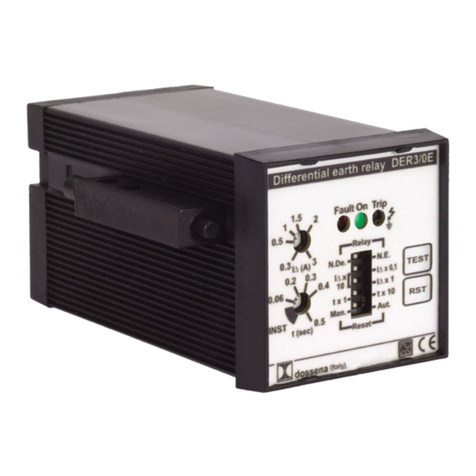
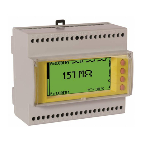
Dossena DER3 User manual

DER3
MU
1140
R
EV
.9
Codice Ordinazione/ Order Code:
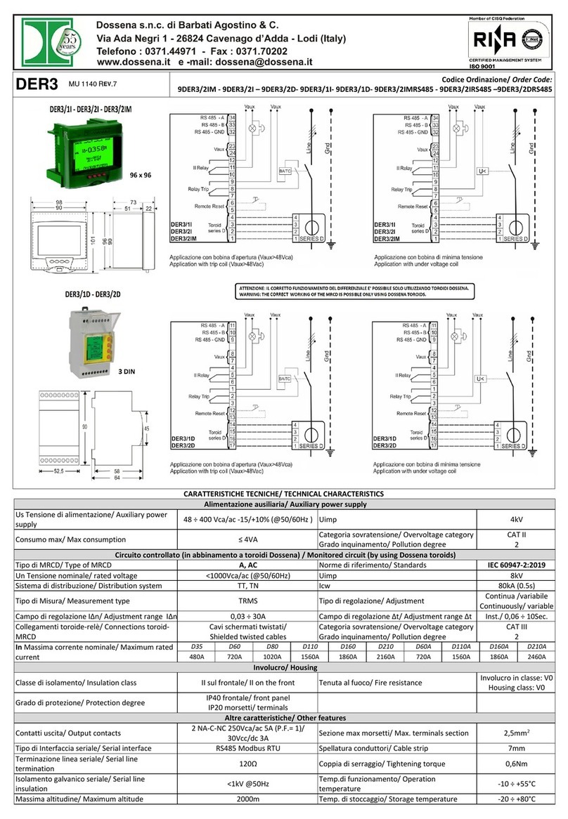
9DER3/1I - 9DER3/2I – 9DER3/2IM- 9DER3/2IRS485 - 9DER3/2IMRS485 - 9DER3/1D - 9DER3/2D –9DER3/2DRS485
CARATTERISTICHE TEC ICHE / TECH ICAL CHARACTERISTICS
Alimentazione
ausiliaria
/
Auxiliary power s
up
p
ly
Us Tensione di alimentazione/ Auxiliary power
supply
(Vau
x
)
48 ÷ 400Vca/ac - 5/+ 0% (@50/60Hz ) Uimp 4kV
Consumo max/ Max consumption ≤ 4VA
Categoria sovratensione
/
Overvoltage category
Grado inquinamento/ Pollution degree
CAT II
2
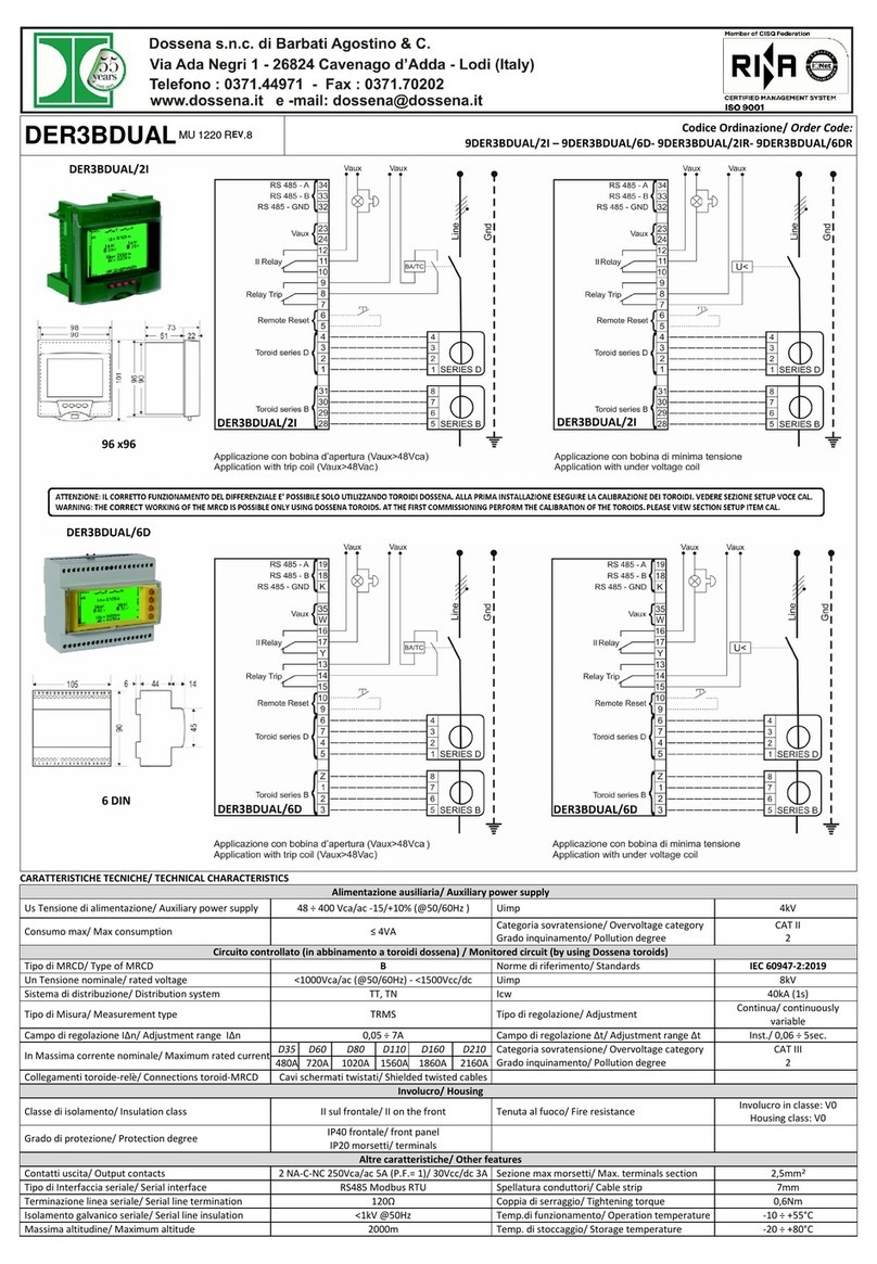
Circuito controllato (in abbinamento a toroidi serie D Dossena) / Monitored circuit (by using Dossena D series toroids)
Tipo di
MRCD/ Type of MRCD
A
/
AC
Norm
e di riferimento
/
Standards
IEC 60947
-
2
Un Tensione nominale/ rated voltage < 000Vca/ac (@50/60Hz) Uimp 8kV
Sistema di distribuzione
/
Distribution system
TT, TN
Icw
80
k
A (
0
,
5
S
ec.
)
Tipo di Misura/ Measurement type TRMS Tipo di regolazione/ Adjustment Continua /variabile
C
ontinuously
/
variable
Campo di regolazione I
Δ
n
/
Adjustment range
I
Δ
n
0,0
3
0
÷
30
A
Campo di regolazione Δt
/
Adjustment range Δ
t
I
n
st./ 0,06 ÷
5
Sec.
Collegamenti toroide↔relè/ Connections
toroid↔MRCD
Cavi schermati twistati/
Shielded twisted cables
Categoria sovratensione/ Overvoltage category
Grado inquinamento/ Pollution degree
CAT III
2
In Massima corrente ammissibile/ Maximum
load
current
D35
D60
D80
D110
D160
D210
D60A
D110A
D160A
D210A DRT
480A
720A
020A
560A
860A
2 60A
720A
560A
860A
2460A 3900A
Involucro/ Housing
Classe di isolamento/ Insulation class II sul frontale/ II on the front Tenuta al fuoco/ Fire resistance Involucro in classe V0
Housing class V0
Grado di protezione/ Protection degree IP40 frontale/ front panel
IP20
morsetti/
t
erminals
Altre caratteristiche/
Other feat
ures
Contatti uscita/ Output contacts
2 NA-C-NC / NO-C-NC
NA/NO: 250Vca/ac 5A P.F. / 30Vcc/dc 5A
NC
/NC
:
250Vca
/ac
3
A P.F.
/
30Vcc
/dc
3
A
Sezione max morsetti/ Max. terminals section
2,5mm
2
Tipo di Interfaccia seriale/ Serial interface RS485 Modbus RTU Spellatura conduttori/ Cable strip 7mm
Terminazione linea seriale/ Serial line
termination 20Ω Coppia di serraggio/ Tightening torque 0,6Nm
Isolamento galvanico seriale/ Serial line
insulation < kV @50Hz Temp.di funzionamento/ Operation
temperature - 0 ÷ +55°C
Massima altitudin
e/
Maximum altitude
2000m
Temp. di stoccaggio
/
Storage temperatu
re
-
20 ÷ +80°C

Pag 2 di 4
Generalità: I relè differenziali di tipo A/AC della gamma DER3 Dossena, perfettamente conformi alla normativa vigente IEC 60947-2:20 9, possono essere impiegati
su reti BT in corrente alternata di tipo TT e TN. Essi consentono di realizzare un'adeguata selettività della protezione differenziale grazie all'ampia regolazione della
soglia della corrente di dispersione (fino a 30A) e della soglia di ritardo dell'intervento (fino a 5sec). La gamma, ricca di funzionalità, garantisce semplicità di utilizzo,
grande affidabilità, facilità di installazione e rapidità di programmazione. Sull’ampio display sono visualizzate in modo chiaro le grandezze e i parametri. La variazione
del colore di fondo indica con immediatezza lo stato di funzionamento dello strumento (Verde= Vigilanza, Azzurro= Programmazione, Rosso= Allarme/Intervento).
PRECAUZIO I DI SICUREZZA E ISTRUZIO I DI I STALLAZIO E
Tutte le operazioni di installazione e manutenzione devono essere eseguite da personale qualificato in assenza di tensione ed in totale regime di sicurezza elettrica,
nel rispetto delle normative vigenti.
) Prima di alimentare l’apparecchiatura DER3 verificare di aver eseguito correttamente tutti i collegamenti necessari.
2) Installare SEMPRE il differenziale con i toroidi serie D.
3) La sezione dei conduttori deve essere tale che la resistenza totale di ciascuna connessione DER3 ↔ trasduttore sia inferiore a 0,5Ω.
4) Ridurre al minimo la distanza dei collegamenti tra DER3 e trasduttore tenendoli il più lontano possibile da cavi di potenza; utilizzare cavi twistati (mantenere
separato il circuito di misura da quello di prova) e schermati con lo schermo connesso a terra in un solo punto.
STATO DI ORMALE VIGILA ZA (display verde)
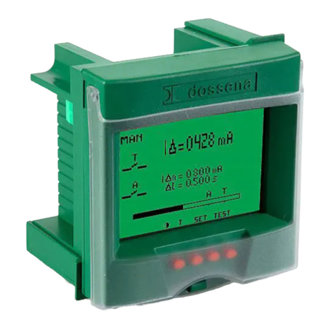
Versione da incasso Versione modulare
I∆: visualizzazione in vero valore efficace (TRMS) della corrente di dispersione in A.
I∆n: s
oglia di corrente di dispersione nominale impostata.
∆t= tempo limite di non intervento impostato.
Istogramma: rappresenta graficamente la misura della corrente di dispersione del
sistema in % di
I∆n
(solo per DER3/2D-2I-2IM).
A= visualizzazione grafica della soglia di allarme impostata (solo per DER3/2D-2I-2IM).
T= visualizzazione grafica della soglia di trip impostata.
Funzione dei pulsanti:
: Premere per variare il contrasto del diplay
SET
=
premere per almeno 3 secondi per entrare nel SET UP.
TEST = premere per eseguire il test.
Il test verifica l'intero sistema di protezione differenziale (DER3 + toroide serie D + B.A.). Premendo il tasto test, il display si colorerà di rosso, il relè di TRIP e il 2° relè
cambieranno di stato. Compariranno lampeggianti in serie le scritte TESTING – TEST OK – TRIP in caso di TEST eseguito correttamente. Se il riarmo è impostato su
manuale (MAN) premere il tasto RESET per riarmare il differenziale.
In caso di test non eseguito correttamente comparirà la scritta TEST KO.
RST
= premere RST per eseguire il
reset
manuale (appare solo se impostato in modalità manuale “MAN”)
.
STATO DI SETUP (display azzurro)
SET = premere il tasto SET per 3 secondi per entrare nel SET UP (display apparirà azzurro).
▼premere per passare da un parametro all’altro in modo ciclico
+/- Premere per modificare il parametro selezionato.
SET premere SET per 3 secondi per uscire dal SET UP salvando i parametri impostati.
Dopo circa 3 minuti di inattività il DER3 esce automaticamente dal SET UP senza salvare le modifiche.
NOTA: nelle versioni 2D le voci di setup appaiono sequenzialmente una alla volta.
ote:
Nella fase di SETUP i
n caso di Allarme/Trip,
il
DER3
interverrà secondo le impostazioni
d
el precedente SETUP. Per
vedern
e
la causa, uscire
dal S
ETUP.
PARAMETRI RA GE
[DEFAULT]
LEVEL IΔn (A)= Soglia della corrente di dispersione nominale. L’intervento del relè di TRIP avverrà al superamento dell’85% del valore IΔn
impostato.
0,03 ÷ 30A [0,03A]
DELAY ΔT= Tempo limite di non intervento (Sec): ritardo entro il quale una corrente differenziale più elevata di IΔn impostata può fluire nel
DER3
senza provocar
n
e l'intervento
(se = “I
NST” il differenziale funzionerà senza ritard
o
,
con intervento Istantaneo).
INST/0,06 ÷ 5Sec.
[
0
,
060
S
]
ALA MODE= Rappresenta lo stato di riposo del relè di allarme. E’ normalmente aperto (NDE) e si chiude in presenza di allarmi. In caso di NE
il relativo contatto diventerà annerito. NDE/NE [ DE]
TRIP MODE= Rappresenta lo stato di riposo del relè di TRIP. E’ normalmente aperto (NDE) e si chiude quando la IΔ supera la IΔn. In caso di
N
E
il relativo contatto diventerà annerito
.
NDE/NE [ DE]
RST MODE=
Modalità
di funzionamento del RESET:
manuale
o automatico.
In modalità MAN, a seguito di uno scatto per I
Δ>IΔn, la scritta
“TEST” diventa “RST” e permetterà quindi il RESET della condizione di TRIP (solo se IΔ < 80%*IΔn). MAN/AUTO [MA ]
ALARM LEV= Soglia d’allarme. Al superamento di tale soglia si genera una condizione di allarme. Nel caso in cui si voglia disabilitare questo
parametro impostare OFF tenendo premuto il tasto -. Nel caso si voglia che il 2° relè funzioni come secondo relè di trip (T) impostare TT
tenendo premuto
il tas
t
o
+
.
OFF/ 5mA÷85% IΔn/TT
[OFF]
BA ALARM= Se impostato su ON, sono vigilati costantemente la continuità della bobina di apertura e la sua alimentazione, generando
allarme in caso di anomalia. In caso di bobine a 24V impostare BA ALARM = OFF ON/OFF [O ]
TORO TYPE= Scelta del trasduttore toroidale (T35 - T60 - T80 - T 0 - T 60 - T2 0 – T80S (toroide sommatore rapporto di trasformazione
TA ≤ 500/5) – T80SX (toroide sommatore rapporto di trasformazione TA ≥ 600/5) - T300M (toroide moltiplicatore) – T60A – T 0A – T 60A -
T2 0A - TDRT).
T35 ÷ TDRT [T35]
UM ODE= Nodo di rete: assegnare ad ogni singolo DER3 un numero di nodo (solo per versioni dotate di uscita seriale RS485).
00 ÷ 200 [001]
BAUD
RATE
=
Configurazione velocità seria
l
e
e
bit parità
(N=nessuna
,
E=pari, O
=
dispari)
(
s
o
lo
per
ver
sioni dotate di uscita seriale RS485
)
.
4800
÷ 38400
[192
0
0
]
PSW= Per impostare la password inserire il numero scelto nel relativo campo. Premere per 3 secondi il tasto SET per uscire dal setup
salvando l’impostazione. Da questo momento ogni volta che si entra in setup sarà possibile visualizzare i parametri di funzionamento ma
non sarà possibile in alcun modo modificarli (nemmeno da scritture seriali per i modelli che ne siano provvisti). Al posto dei tasti freccia sarà
visualizzato o un lucchetto (versione modulare) o la scritta “LOC” (versione da incasso).
Per disabilitare la password entrare in setup ed inserire il numero scelto nel campo PSW permettendo di procedere alla modifica dei
parametri
.
D
a
q
u
e
s
t
o
m
o
m
e
n
t
o
i
l dispositivo sarà
sprovv
isto
di
password.
(OFF)/000 ÷ 9998
[OFF]

Pag 3 di 4
Introduction: The residual current devices, type A/AC Dossena DER3 series, fully compliant with IEC 60947-2: 20 9, can be used in LV network in AC, TT and TN type.
The series offers a wide range of adjustment of the I∆n threshold (up to 30 A) and of the delay time (up to 5 sec). DER3 guarantees ease of use, reliability, and speed
of programming. The measures and parameters are clearly displayed. The variation of the background colour immediately indicates the instrument’s operating status
(Green = residual current protection active, Blue = setup, Red = Alarm / Intervention).
I STALLATIO SUGGESTIO S A D SAFETY PRECAUTIO :
All installation and maintenance operations must be carried out by qualified personnel in the absence of voltage and in a total electrical safety regime, in compliance
with the safety regulations.
) Before powering the DER3, check that all connections have been executed properly.
2) ALWAYS install DER3 combined with Dossena toroidal transducer D series.
3) The cross-section of the conductors must be such that the total resistance of each DER3 ↔transducer connection is less than 0.5Ω.
4) Minimize the distance connections between DER3 and transducer and keep them away from power cables; use twisted shielded cables with the shield connected
to ground at one point only (keep the measurement circuit separate from test circuit).
ORMAL VIGILA CE (GREE DISPLAY)
Front
-
panel v
ersio
n
Modu
lar
v
ersion
I∆: Display in true rms value (TRMS) of the residual current in A.
I∆n:
Set threshold of the nominal residual current.
∆t= Set the limiting non-actuating time.
Histogram: represents the measurement of the residual current of the system in % of I∆n
(only for models DER3/2D - 2I - 2IM).
A= graphic visualization of the set alarm threshold (only for models DER3/2D - 2I - 2IM).
T= graphic visualization of the set TRIP threshold.
Keys function:
= press this button to adjust the contrast
SET = press for at least 3 seconds to enter in SET UP.
TEST = press to perform DER3 test.
The test checks the complete protection system (DER3+ toroid series D + T.C.). Push test button to start the test. Display becomes red. The TRIP relay and the 2
nd
relay change state. The writings TESTING - TEST OK - TRIP will appear flashing in series in case of TEST performed correctly. If the reset is set to manual (MAN), press
the RESET key to reset the differential relay. If the test is not performed correctly, the message TEST KO will appear.
RST = reset button, active only in the manual reset mode.
SETUP (BLU DISPLAY)
SET press SET button for at least 3 seconds to enter in SET UP (display becomes blue).
▼press to switch from one parameter to another in a cyclic way.
+/- press to modify the selected parameter.
press SET button for at least 3 seconds to exit from SETUP and save the parameters.
DER3 automatically exits from SETUP without saving modification, after 3 minutes of inactivity.
NOTE: in the modular versions the setup items appear sequentially one at a time.
o
te
:
The new setup pa
rameters will be operative on
ly after saving.
If an alarm
occurs
i
n
set
up, it is caused by th
e previous
ly
set parameter
s.
PARAMETERS RA GE
[DEFAULT]
LEVEL IΔn (A)= Threshold of the nominal residual current. The intervention of the TRIP relay will occur when 85% of the set IΔn value is
exceeded.
0,03 ÷ 30A [0,03A]
DEL
AY
ΔT
=
L
imiting no
n
-
actuating time
.
If you set it to
"INST",
t
he
tripping mode beco
mes inst
antaneous.
INST
/
0,06
÷
5
Sec.
[
0
,
060
S
]
ALA MODE= It represents the rest state of the alarm relay. It is normally open (NDE) and closes in the presence of alarms. In case of NE
the relative contact will become blackened. NDE/NE [ DE]
TRIP MODE= It represents the rest state of the TRIP relay. It is normally open (NDE) and closes when the IΔ exceeds the IΔn. In case of
N
E
the relative contact will become blackened.
NDE/NE [ DE]
RST MODE
=
manual or au
tomatic
.
After a trip fo
r I
Δ
> I
Δ
n, the written "
TEST
" bec
omes "
R
ST
" and will therefore allow the
RESET of
the TRIP
condition (only if I
Δ
<
80%*
I
Δ
n)
.
MAN/AUTO [MA ]
ALARM LEVEL= Alarm threshold. When this threshold is exceeded, an alarm condition is generated. If you want to disable this
parameter, set OFF by holding down the key -. If you want the 2nd relay to work as a second trip relay (T), set TT by keeping the key +
pressed.
OFF/ 5mA÷85% IΔn/TT
[OFF]
BA ALARM= If set to ON, the continuity of the opening coil and its power supply are constantly monitored, generating an alarm in the
event of an anomaly. In case of 24V Trip Coil set parameter BA Alarm = OFF ON/OFF [O ]
TORO TYPE= Toroidal transducer choice (T35 - T60 - T80 - T 0 - T 60 - T2 0 – T80S (adder toroid tranformation ratio CTs ≤ 500/5) –
T
80SX
(adder tor
oid tra
nformation ratio
CTs
≥
6
00/5
)
-
T
3
00M
(multiplier tor
oid)
–
T6
0A
–
T
0A
–
T
60A
-
T
2 0A
-
TDRT
)
.
T35 ÷ TDRT [T35]
UM
ODE
=
Network co
nfiguration
:
assign
to each
DER3
a no
de number
(o
nly
for v
ersions equipped with serial output R
S485)
.
00
÷
200
[
001
]
BAUDRATE = Serial speed configuration and parity bit (N= none, E= even, O=odd) (only for versions equipped with serial output RS485).
4800 ÷ 38400 [19200
]
PSW= To set the password, enter the chosen number in the relevant field. Press the SET button for 3 seconds to exit the setup and save
the setting. From this moment on, every time you enter setup it will be possible to view the operating parameters but it will not be
possible to modify them in any way (not even from serial writings for models that are equipped with them). Instead of the arrow keys,
either a padlock (modular version) or the wording “LOC” (front-panel version) will be displayed.
To disable the password, enter setup and enter the chosen number in the PSW field, allowing you to change the parameters. From this
moment the device will be without a password.
(OFF)/000 ÷ 9998
[OFF]

Pag 4 di 4
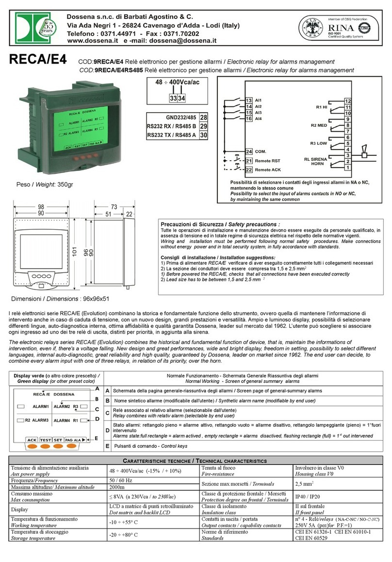
ALLARMI/ALARMS
MSG COLORE/ COLOR EVE TI/ EVE TS CAUSA/ CAUSE
ALA
giallo fisso
yellow
Il 2° relè cambia di stato
Incremento dell'istogramma (solo per DER3/2D-2I-
2IM).
Incremento del valore di corrente I∆.
The 2
nd
relay switches.
Increasing of histogram (only for DER3/2D-2I-2IM).
I
ncre
asing
of
I
∆
current value
.
Superamento soglia allarme
La corrente di dispersione I∆ ha superato la soglia di allarme .
Alarm thereshold exceeded:
The residual current I∆ has exceeded alarm threshold.
TC – BA
ALARM
giallo fisso
yellow
Il 2° relè cambia stato.
The 2
nd
relay switches.
ALLARME B.A.: Possibile problema della bobina di apertura (disconnessa o
senza alimentazione) o interruttore non armato. ATTE ZIO E: Se
l’impianto non fa uso della bobina di apertura o è installata una bobina a
24V occorre impostare BA ALARM = OFF.
T.C. ALARM: Possible trip coil problem (disconnection, no voltage) or no
armed circuit breaker. WAR I G: if no Trip coil is present in the system or
the T.C. voltage is 24V set BA ALARM = OFF.
TRIP
rosso fisso
red
Il relè di Trip cambia di stato.
Incremento dell'istogramma (solo per DER3/2D-2I-
2IM)
Blocco della visualizzazione sul valore di corrente per
cui è avvenuto l'intervento.
The Trip relay switches
The increasing of histogram (only for DER3/2D-2I-2IM)
The visualization is blocked on current value for which
DER3
has been
tripped
.
ALLARME DI TRIP
La corrente di dispersione I∆ ha superato l'85% della soglia I∆n
TRIP ALARM (I∆n)
The residual current I∆ has exceeded 85% of threshold I∆n
O TORO
rosso fisso
red
Il relè di Trip cambia di stato.
Il 2° relè cambia di stato
The Trip relay switches.
The 2
nd
relay switches.
ALLARME TOROIDE
Problema toroide: o manca un collegamento o possibile presenza di
cortocircuiti sugli avvolgimenti
TOROID ALARM
Toroid problem: either there is a disconnection or there is a short in its
windings.
TEMP
rosso fisso
red
ALLARME TEMPERATURA
Eccessiva temperatura interna.
TEMPERATURE ALARM
Exc
essive
internal temper
ature
.
TEST KO
rosso fisso
red
Il relè di Trip cambia di stato.
The Trip relay switches
Il test è stato eseguito ed ha avuto esito negativo.
The test was performed and failed.
OTE SPECIALI
SPECIAL OTES:
FU ZIO ALITA’ MEMOR
IA DI
I TERVE TO (SOLO
PER
DER3/2IM):
Il DER3/2IM è
in grado di indicare il proprio intervento anche in mancanza di alimentazione. A
display spento, premendo il primo tasto partendo da sinistra se il differenziale si
illumina di rosso l’intervento dell’interruttore è stato attivato dal DER3/2IM.
Attenzione: il DER3/2IM sarà in grado di mantenere la memoria dell’intervento fino
ad un massimo di 4 giorni e tale tempo si ridurrà dopo ogni consultazione.
I TERVE TIO MEMORY FU CTIO ALITY (O LY FOR DER3
/
2IM):
The DER3
/
2IM is
able to indicate its intervention even in the absence of power supply. With the display
off, by pressing the first button from the left, if the device lights up red, the
intervention of the switch has been activated by the DER3/2IM.
Attention: the DER3/2IM will be able to keep the memory of the intervention up to a
maximum of 4 days and this time will be reduced after each consultation.
This manual suits for next models
13
Table of contents
Languages:
Other Dossena Relay manuals

Dossena
Dossena RECA/E8CC User manual

Dossena
Dossena DER3/1DL User manual

Dossena
Dossena DER3 User manual

Dossena
Dossena DER3/0 Series User manual

Dossena
Dossena DER3B-MED Series User manual

Dossena
Dossena SRI3/D2 User manual

Dossena
Dossena SRI3/H2 User manual

Dossena
Dossena 9DER3/1DLCC User manual

Dossena
Dossena RECA/E8 User manual

Dossena
Dossena SRI3/I2 User manual