Doyon DRIP1TLO User manual

DRIP1TLO, E236TLO, E336TLO & E460TLO
IMPORTANT SAFETY INSTRUCTIONS
SAVE THESE INSTRUCTIONS
DANGER
TO REDUCE THE RISK OF FIRE OR ELECTRIC SHOCK, CAREFULLY FOLLOW
THESE INSTRUCTIONS.
TABLE OF CONTENTS
SECTION « A » DESCRIPTION PAGE
Introduction . . . . . . . . . . . . . . . . . . . . . . . . . . . . . . . . . . . . . . . . . . . . . . . . . A1
Construction . . . . . . . . . . . . . . . . . . . . . . . . . . . . . . . . . . . . . . . . . . . . . . . . A2
Shipping . . . . . . . . . . . . . . . . . . . . . . . . . . . . . . . . . . . . . . . . . . . . . . . . . . . . A2
Warnings . . . . . . . . . . . . . . . . . . . . . . . . . . . . . . . . . . . . . . . . . . . . . . . . . . . A3
Distances to respect . . . . . . . . . . . . . . . . . . . . . . . . . . . . . . . . . . . . . . . . . . . A4
Installation . . . . . . . . . . . . . . . . . . . . . . . . . . . . . . . . . . . . . . . . . . . . . . . . . . A4
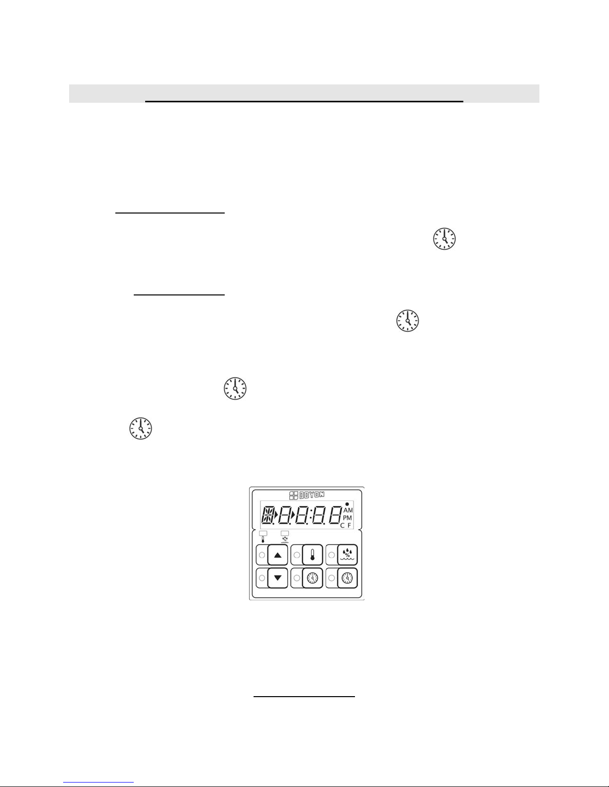
Operation of the digital control . . . . . . . . . . . . . . . . . . . . . . . . . . . . . . . . . . A5
Troubleshooting . . . . . . . . . . . . . . . . . . . . . . . . . . . . . . . . . . . . . . . . . . . . . A6
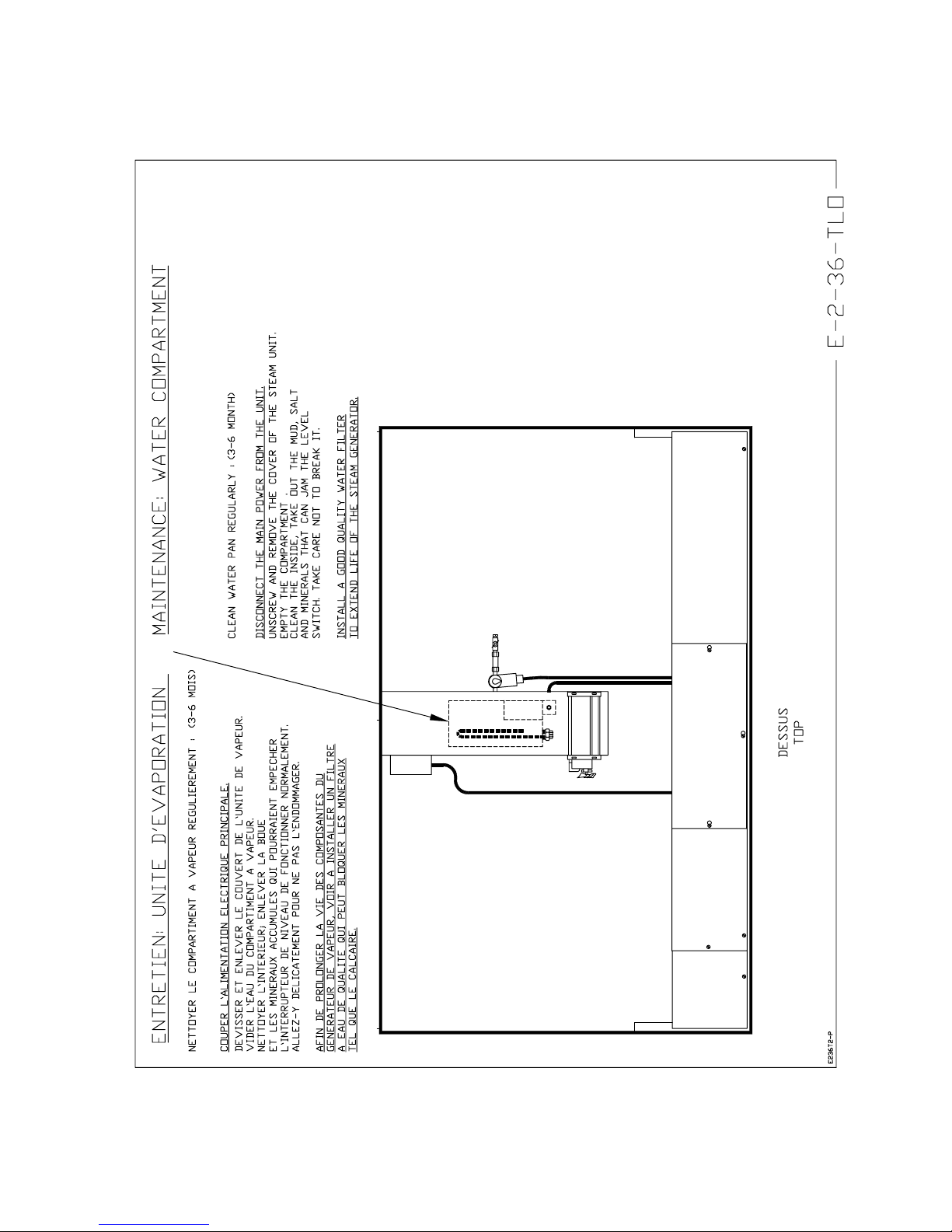
Maintenance and cleaning . . . . . . . . . . . . . . . . . . . . . . . . . . . . . . . . . . . . . . A7
For more information, please contact our office: . . . . . . . . . . . . . . . . . . . . A9
SECTION « B » DIMENSIONS
DRIP1 TLO. . . . . . . . . . . . . . . . . . . . . . . . . . . . . . . . . . . . . . . . . . . . . . . . . B1
E236 TLO . . . . . . . . . . . . . . . . . . . . . . . . . . . . . . . . . . . . . . . . . . . . . . . . . B3
E336 TLO. . . . . . . . . . . . . . . . . . . . . . . . . . . . . . . . . . . . . . . . . . . . . . . . . . B6
E460 TLO. . . . . . . . . . . . . . . . . . . . . . . . . . . . . . . . . . . . . . . . . . . . . . . . . . B9
SECTION « E » COMPONENT PARTS
Front view component parts for all models . . . . . . . . . . . . . . . . . . . . . . . . E1
DRIP1 TLO . . . . . . . . . . . . . . . . . . . . . . . . . . . . . . . . . . . . . . . . . . . . . . . . E3
E236 TLO. . . . . . . . . . . . . . . . . . . . . . . . . . . . . . . . . . . . . . . . . . . . . . . . . . E5
E336 TLO. . . . . . . . . . . . . . . . . . . . . . . . . . . . . . . . . . . . . . . . . . . . . . . . . . E9
E460 TLO. . . . . . . . . . . . . . . . . . . . . . . . . . . . . . . . . . . . . . . . . . . . . . . . . . E11

SECTION « G » ELECTRIC SCHEMATICS
DRIP1 TLO - 120V/208V/1PH & 120V/240V/1PH . . . . . . . . . . . . . . . . G1
DRIP1 TLO - 220V/1PH/50 Hz . . . . . . . . . . . . . . . . . . . . . . . . . . . . . . . . G2
E236 TLO - 120V/208V/1PH & 120V/240V/1PH . . . . . . . . . . . . . . . . . . G3
E236 TLO - 220V/1PH/50HZ . . . . . . . . . . . . . . . . . . . . . . . . . . . . . . . . . . G4
E336 TLO - 120V/208V/1PH & 120V/240V/1PH . . . . . . . . . . . . . . . . . . G5
E336 TLO - 220V/1PH/50HZ . . . . . . . . . . . . . . . . . . . . . . . . . . . . . . . . . . G6
E460 TLO - 120V/208V/1PH & 120V/240V/1PH . . . . . . . . . . . . . . . . . . G7
E460 TLO - 220V/1PH/50HZ . . . . . . . . . . . . . . . . . . . . . . . . . . . . . . . . . . G8
Warranty . . . . . . . . . . . . . . . . . . . . . . . . . . . . . . . . . . . . . . . . . . . . . . . . . . .
FAM-ET-A.DOC REV. 28/11/2005

A1
INSTALLATION AND MAINTENANCE MANUAL
The manufacturer suggests to read this manual carefully.
This proofer is manufactured with first quality material by experienced technicians. Proper
installation and maintenance will guarantee a reliable service for years to come.
A nameplate fixed to the front of the proofer specifies the serial number, model number, number of
phase, amperage, voltage and frequency.
Drawings, electrical diagram and replacement part numbers are included in this manual. The
electrical diagram is affixed in the control panel located on the top of the proofer.
ATTENTION
DOYON is not responsible for damages to the property or the equipment caused
by personnel who is not certified by known organizations. The customer is
responsible for finding qualified technicians in electricity and plumbing for the
installation of the oven.

A2
C O N S T R U C T I O N
You just bought the most advanced proofer in the world, the "DOYON" technology at its best. This
proofer is manufactured using the highest quality components and material.
The DOYON equipments are designed with parts that are easy to find.
S H I P P I N G
For your safety, this equipment is verified by qualified technicians and carefully crated before
shipment. The freight company assumes full responsibility concerning the delivery in good condition
of the equipment in accepting to transport it.
IMPORTANT
RECEPTION OF THE MERCHANDISE
Take care to verify that the received equipment is not damaged before signing the delivery receipt. If
a damage or a lost part is noticed, write it clearly on the receipt. If it is noticed after carrier left,
contact immediately the freight company in order that they do their inspection.
We do not assume the responsibility for damages or losses that may occur during transportation.

A3
W A R N I N G S
FOR YOUR SAFETY
DO NOT STORE OR USE GASOLINE OR OTHER FLAMMABLE VAPORS
AND LIQUIDS IN THE VICINITY OF THIS OR ANY APPLIANCE.
INSTALLATION AND SERVICE
Installation and service must be done by specialized technicians. Contact a certified electrician and
plumber for set up.
The proofer must be connected to the utility and electrically grounded in conformity to the effective
local regulations. If these are not established, the oven must be connected according to the Canadian
Electrical Code (CSA-C22.1-XX) or National Electrical Code (NFPA 70-XX). Refer to last
edition year for XX.

A4
DISTANCES TO RESPECT
•Top of the proofer: a clearance of 24 to 36 inches to the ceiling must exist to permit
maintenance.
•Back and sides: 4 inches.
I N S T A L L A T I O N
IN GENERAL
Take off the packaging material with care. Take off all the material used for packing and accessories.
Each unit is set up to be used with the electrical supply specified on the nameplate fixed on the front
of the unit.
1. To the electrician
Electrical supply installation must be in accordance with the electrical rating on the nameplate.
WARNING
The electrician must make sure that the supply cable does not come in contact
with the oven top which becomes hot.
2. To the plumber
This equipment is to be installed to comply with the applicable federal, state, or local plumbing
codes.
Connect the steam system (1/4 NPT) to the water distribution network.
We highly recommend to use a water softener to eliminate minerals in the water. We suggest you to
use CUNO # CFS6135 (Doyon part number PLF240).
WARNING
Do not adjust the needle valves, it has been done at the factory.

A5
OPERATION OF THE DIGITAL CONTROL
1. Turn the main switch to " 1 ".
2. The light inside the proofer will turn ON and the digital control will indicate a code. Then,
"PREH" will flash.
3. "PREH" will be displayed on the control until it reaches the set temperature.
To check and modify:
Temperature settings : Press and hold down for 2 seconds the temperature key
and adjust with the UP and DOWN arrows. Then, press
temperature key to save data or " red " to exit
without saving.
Humidity settings : Press and hold down for 2 seconds the humidity key and
adjust with the UP and DOWN arrows. Then, press
humidity key to save data or "red " to exit without
saving.
4. When the control reaches the set parameters, "PREH" will disappear and the timer display will
appear.
To start the timer, press " green ", the timer will stop blinking and start countdown.
At the end of the countdown an alarm will go off and " READY " will appear on the display.
Press " red " to stop the alarm.
5. When proofing cycle is completed, turn OFF the switch.
When the proofer is not in operation, open the doors to let out the humidity and prevent
mould.
P.S. The doors should not be opened unnecessarily to conserve the heat and humidity in the
proofer. The water pan under the proofer's doors should be cleaned daily.
POWER FAILURE
When the power comes back, the proofer will start automatically. It is recommended, when a power
failure occurs, to turn off the unit in order to avoid it from starting without supervision.

A6
TROUBLESHOOTING
BEFORE CALLING FOR SERVICE,
ANSWERS TO THE MOST FREQUENT QUESTIONS
Always cut off the main power before replacing any parts. Take care of water piping and
electric cable.
Control parts on the front. To remove parts from front panels, you have to
go on the top of the unit.
Control panel, proofer unit and refrigeration
units.
They are located on the top of the unit.
Questions Solutions
The unit does not turn on when installed. Check if the light is on.
Check if the proofer’s switch is on.
Check the breaker of the building.
Check the breakers located on the front and in
the electrical control panel on the top of the
unit.
The blower runs but the unit does not
produce heat.
Make sure that the thermostat is adjusted to the
desired temperature (over ambient temperature)
and that the pilot light is lit. Check the breakers
in the electrical control panel.
The blower runs but the unit does not
produce steam.
Check humidity control settings. Verify if the
water valve of the building is open and if water
goes into the proofer’s unit located on the top
of the unit. Check if the water needle valve (of
the unit) is opened between a half to one turn.
Just close it and open it one turn maximum.
Check the breakers in the electrical panel.

A7
MAINTENANCE AND CLEANING
Step by step Recommendations
Clean the inside of the unit with water and
soap.
We recommend and sell:
Dirt Buster III : Action foam cleaner
CHEMCO
Part number : NEB201
Clean the unit exterior with a stainless steel
polish.
We recommend and sell:
Stainless steel cleaner
SANY or CURTIS (comestible)
Part number : NES201
Clean the windows with products like Brasso
or equivalents. They are copper cleaners but
good for this use.
We recommend and sell:
Wright's: Cream copper cleaner
J.A. Wright & Co.
Part number : EXC300

A8

A9
FOR MORE INFORMATION,
PLEASE CONTACT OUR OFFICE:
DOYON EQUIPMENT INC.
1255, rue Principale
Linière, Qc, Canada G0M 1J0
Tel. : 1 (418) 685-3431
Canada : 1 (800) 463-1636
U.S. : 1 (800) 463-4273
FAX : 1 (418) 685-3948
Internet: www.doyon.qc.ca

SECTION
B
DIMENSIONS

B1

B2

B3

B4

B5

B6

B7

B8
Other manuals for DRIP1TLO
2
This manual suits for next models
3
Table of contents
Other Doyon Oven manuals