©
2015 Draeger
Medic
al
,
Inc
.
INFINITY M540 QUICK REFERENCE GUIDE |9
THIS GUIDE IS INTENDED
FOR REFERENCE
ONLY. REFER
TO
INSTRUCTIONS FOR USE
MANUAL.ADDITIONAL INFORMATION
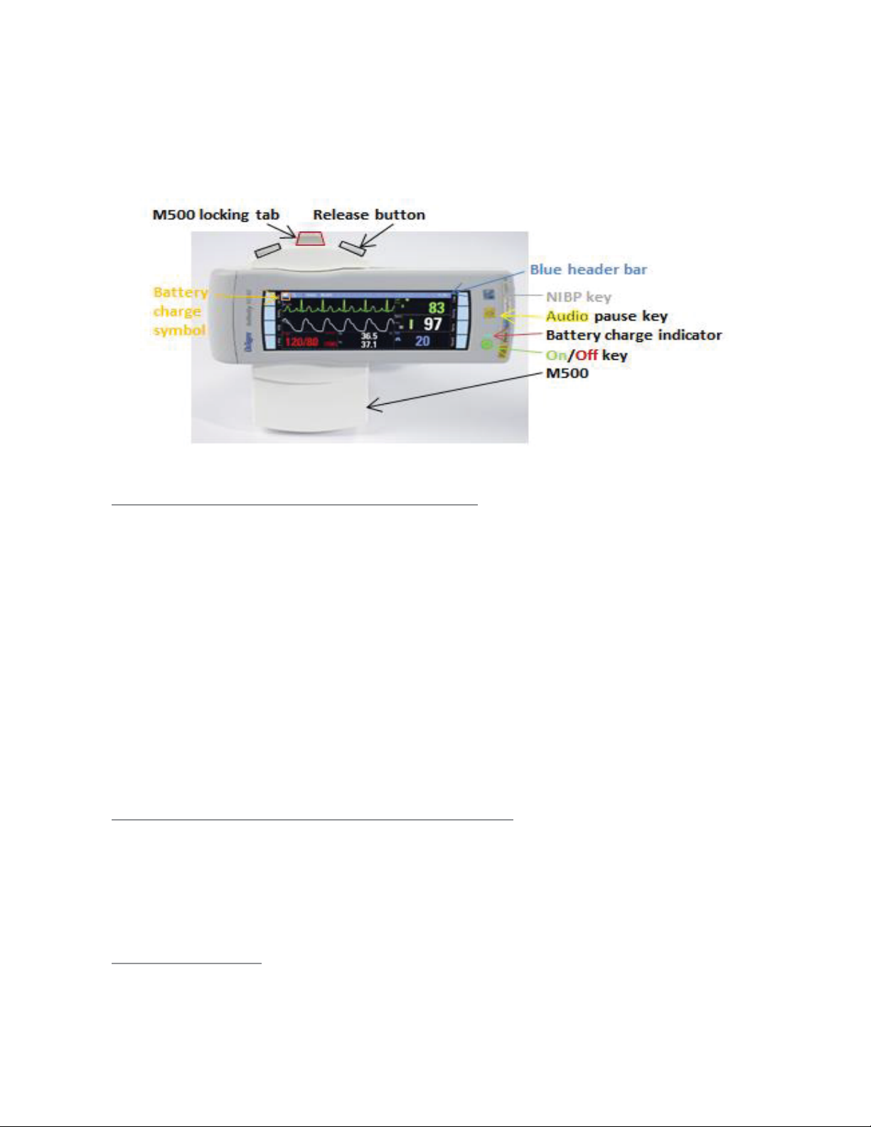
ON/OFF FIXED KEY
- Turns the M540 on or off. The button LED flashes when the
M540 is undocked; is solid when the M540 is docked.
BATTERY LED SYMBOL
- This symbol lights up when the M540 is docked to indicate the
battery is being charged; it does not light up when the M540 is
undocked.
AUDIO PAUSE FIXED KEY
- Pauses acoustic alarm signals for two minutes
Note: Quiet Mode is Activated – If a new alarm condition with a priority
higher than the currently paused alarm occurs, a truncated alarm tone
sounds. In addition, the alarm is represented by visual alarm signals corre-
sponding to the alarm priority. If the new alarm is of lower priority than the
paused alarm, the new alarm condition is only represented by a visual alarm
signal. No acoustic alarm tones sound.
If Quiet Mode is Deactivated - Any new alarm condition breaks through the
Audio Pause period with full acoustic and visual alarm annunciation.
NIBP START/STOP FIXED KEY
- Starts/stops non-invasive blood pressure measurements
TO CALIBRATE THE M540 TOUCH SCREEN
If the Touch screen is out of alignment, calibration should be per-
formed.
1. Push and hold the following two keys simultaneously.
2. Touch each cross appearing successively on screen with finger-
tip.
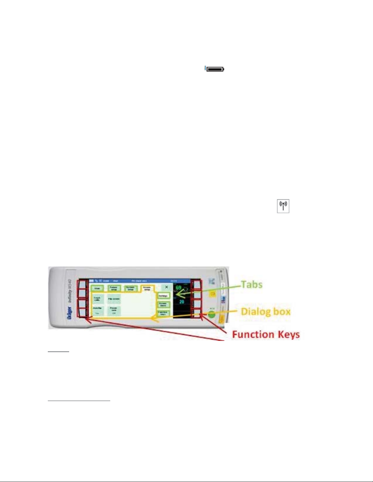
BLUE HEADER BAR