Contents
Page
3
,. 4
5
6
Page
Order List ............................................................. 46
Preparation.. ........................................................
Attaching PM 8030 ............................................ 6
Connecting sensor and pressure measuring line. 6
Connecting sensors to anaesthetic machine ........ 7
Connecting 02 sensor capsule.. ......................... 7
Connecting 02 sensor ........................................ 7
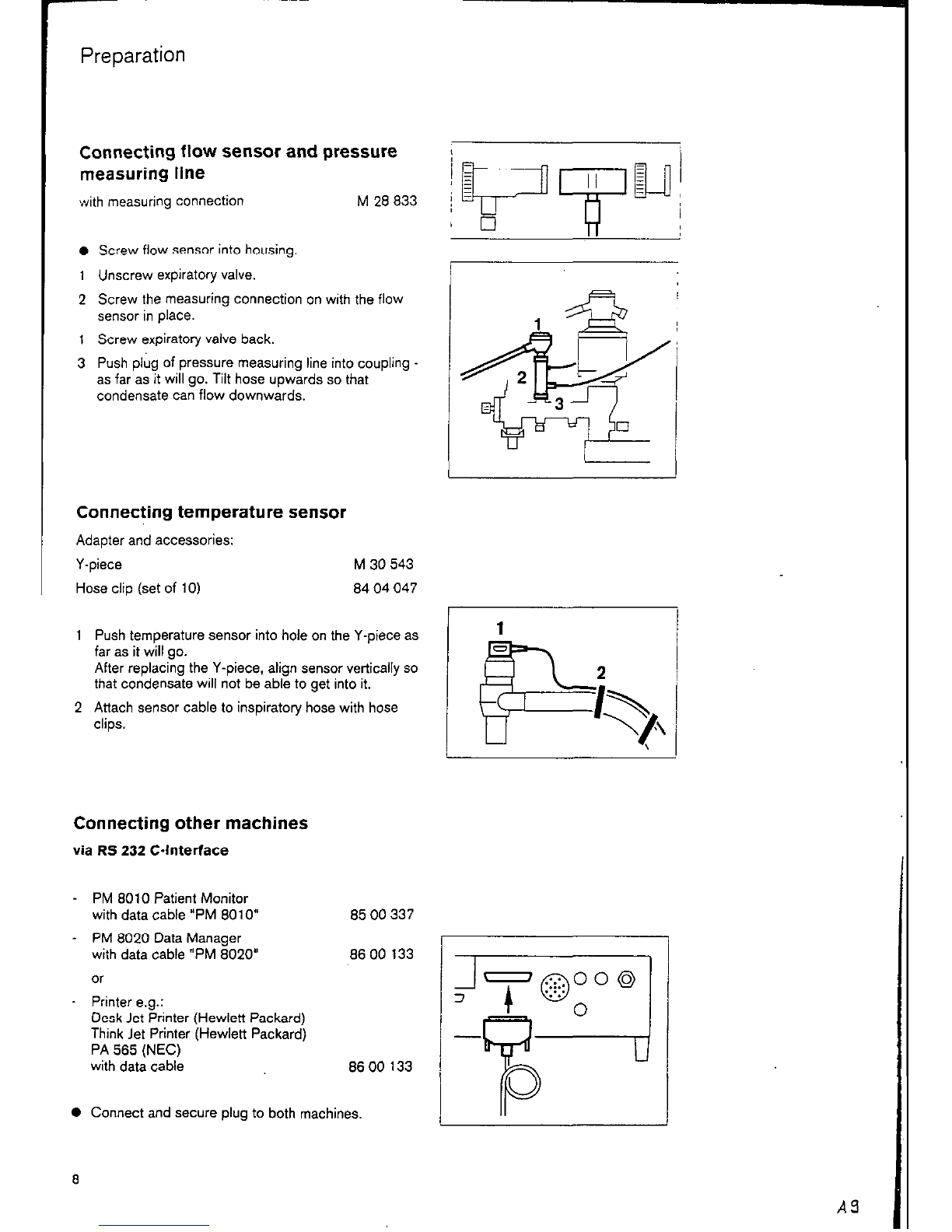
Connecting flow sensor and pressure
measuring line ..................................................... 0
Connecting temperature sensor.. ........................ 8
Connecting other machines ................................ 8
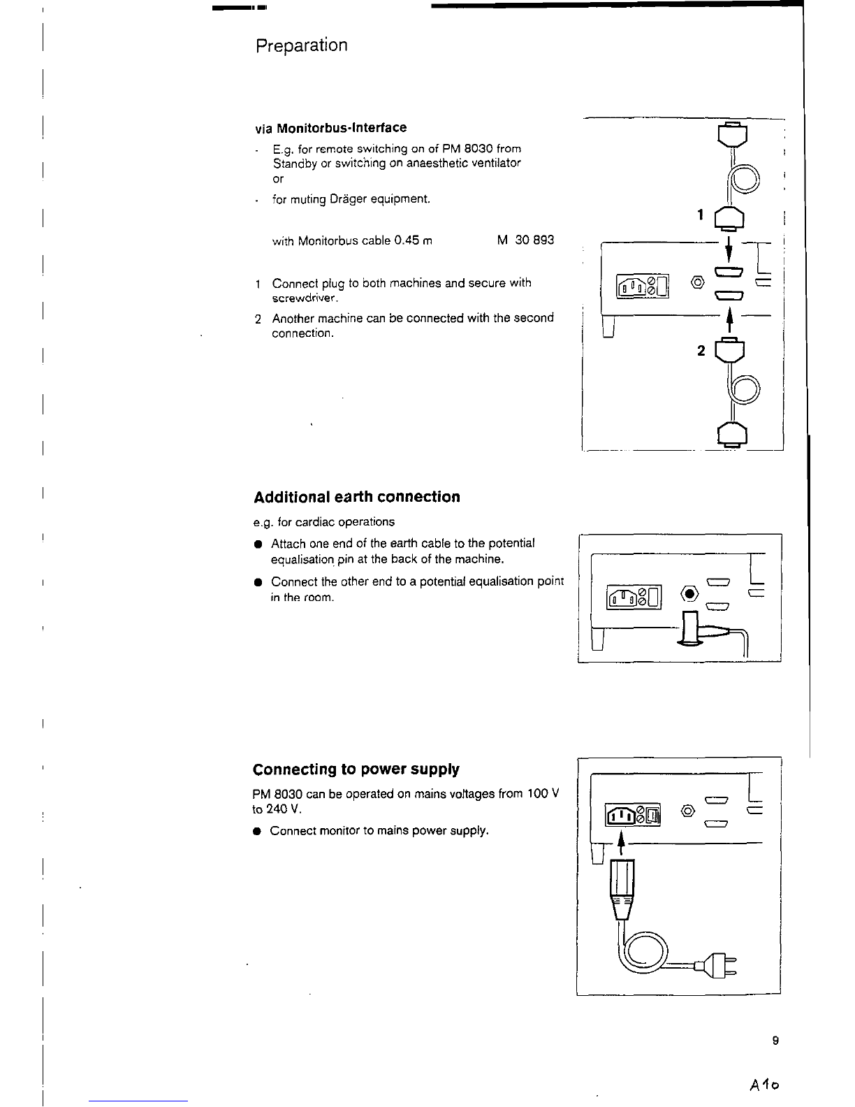
Additional earth connection ................................. 9
Connecting to power supply ............................... 9
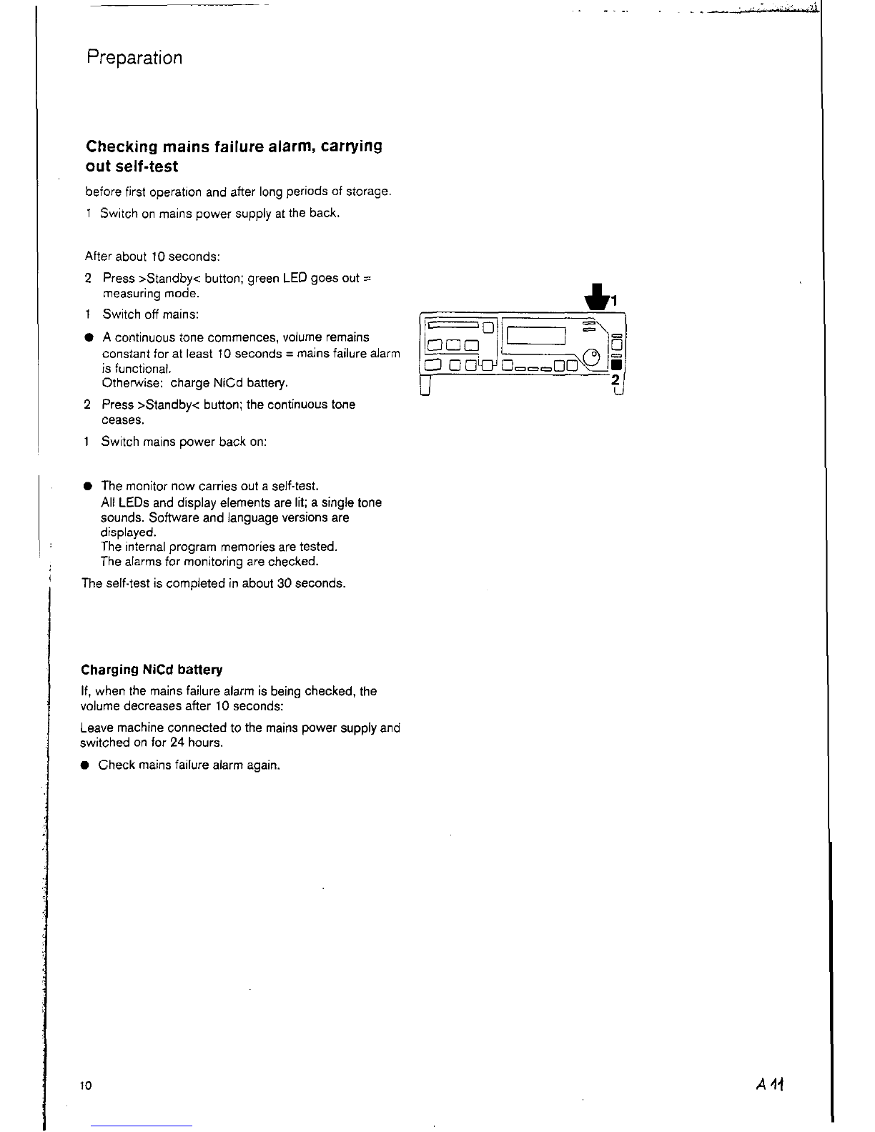
Checking mains failure alarm, carrying out
self-test ............................................................... 10
Appendix ............................................................. .48
Flow measurement measuring principle
and signal processing ........................................ 48
Definition of PEEP and plateau pressure ........... .48
02 measurement. measuring principle
and signal processing ........................................ 49
Anaesthetic agent measurement
measuring principle.. ........................................... 49
Explanation of terms used ................................. .50
For Your Safety and That of Your Patients ....
Intended Use ........ ........ ........... .......... ...... .
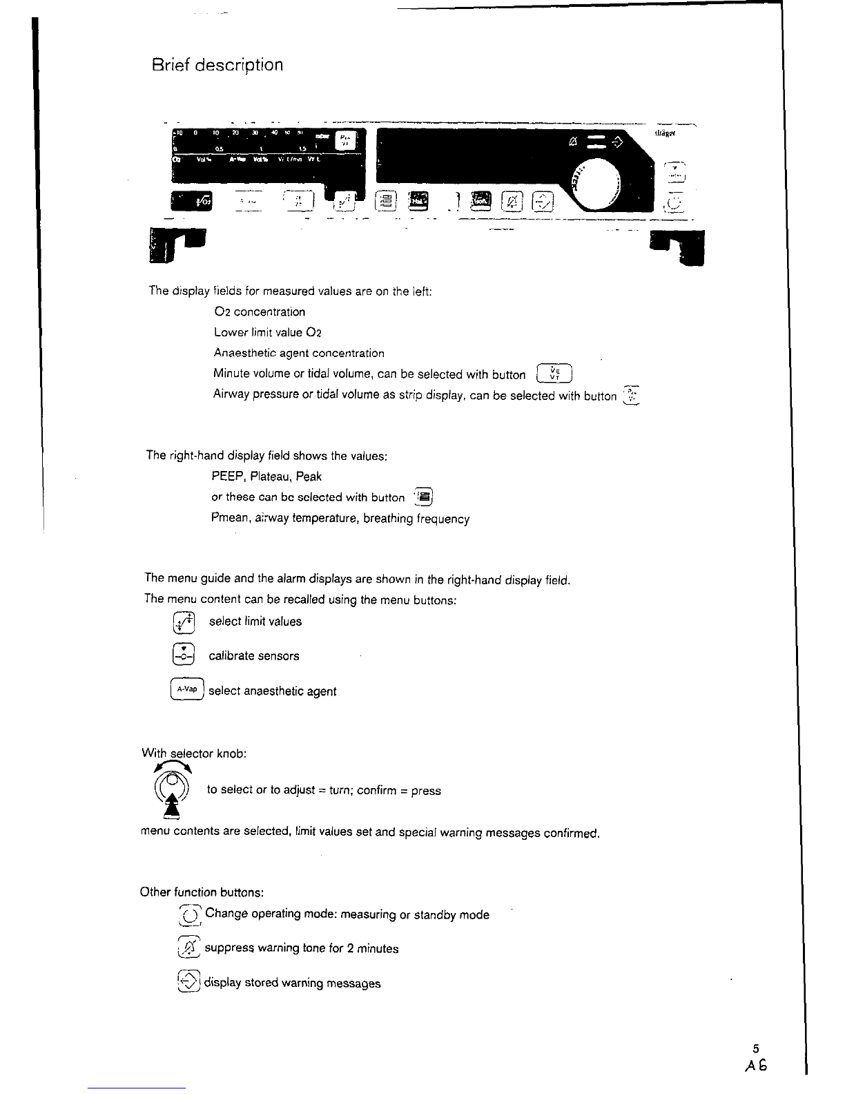
Brief description ................... .......~............... ......
.....
Calibration ............................................................ 11
Calibrating 02 sensor ......................................... 11
02 sensor . checking linearity ............................. 13
Calibrating flow sensor ............................ .......... .13
Cleaning flow sensor .......................................... 14
Calibrating anaesthetic agent sensor.. ................ .15
Operation .............................................................. 16
Carrying out function check ............................... .76
Selecting anaesthetic agent ............................... .18
Setting limit values .............................................. 18
Displaying measured values ............................... .23
Alarms ................................................................ 26
Communication by PM 8030 with other
Driger machines ................................................. 27
Independent documentation ............................... 28
Shut-down .......................................................... 28
Fault - Cause - Remedy ...................................... 29
Care ....................................................................... 33
Stripping down ...................................................... 33
Disinfecting/cleaoing/sterilizing .............................. 34
Checking Function .............................................. 36
Maintenance Intervals ........................................ 37
Configuration.. ..................................................... 38
Setting language of display texts ........................... 38
Interface protocol for PM 8010 or PM 8020 ......... .39
interface protocol for printer .................................. 40
Switching on/off A-VaplAW.Temp. sensors ........... 41
What’s What ................... ..................................... 42
Technical Data ..................................................... 44
Index ...................................................................... 51
2
Al