Dräger X-am 1100 Release Note

D
ST-7452-2005.e
p
s
Multi-Gas Monitor
Technical Handbook
Dräger X-am
®
1100, 1700, 2000
approved as type LQG 00xx

2
Table of Contents
Table of Contents
For Your Safety
. . . . . . . . . . . . . . . . . . . . . . . . . . . . . . . . . . . . . . . . . . . . . . . . . . . . . . . . . . . . . . . . 4
Intended Use
. . . . . . . . . . . . . . . . . . . . . . . . . . . . . . . . . . . . . . . . . . . . . . . . . . . . . . . . . . . . . . . . . . 5
Tests and Approvals
. . . . . . . . . . . . . . . . . . . . . . . . . . . . . . . . . . . . . . . . . . . . . . . . . . . . . . . . . . . . 6
Marking . . . . . . . . . . . . . . . . . . . . . . . . . . . . . . . . . . . . . . . . . . . . . . . . . . . . . . . . . . . . . . . . . . . . . . . 6
Intended Operating Area and Operating Conditions . . . . . . . . . . . . . . . . . . . . . . . . . . . . . . . . . 7
Safety Instructions . . . . . . . . . . . . . . . . . . . . . . . . . . . . . . . . . . . . . . . . . . . . . . . . . . . . . . . . . . . . . . 7
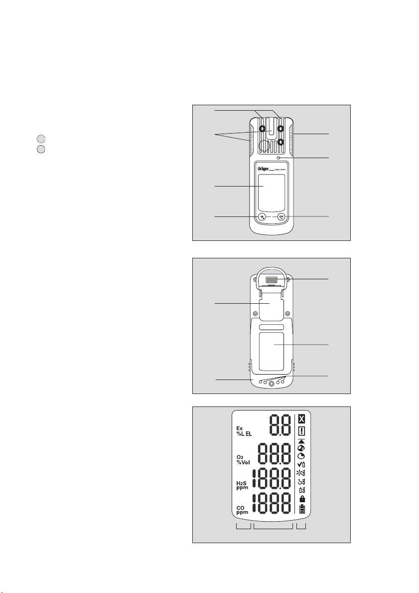
What is What
. . . . . . . . . . . . . . . . . . . . . . . . . . . . . . . . . . . . . . . . . . . . . . . . . . . . . . . . . . . . . . . . . . 8
Front panel . . . . . . . . . . . . . . . . . . . . . . . . . . . . . . . . . . . . . . . . . . . . . . . . . . . . . . . . . . . . . . . . . . . . 8
Rear panel . . . . . . . . . . . . . . . . . . . . . . . . . . . . . . . . . . . . . . . . . . . . . . . . . . . . . . . . . . . . . . . . . . . . . 8
Display . . . . . . . . . . . . . . . . . . . . . . . . . . . . . . . . . . . . . . . . . . . . . . . . . . . . . . . . . . . . . . . . . . . . . . . . 8
Special Symbols . . . . . . . . . . . . . . . . . . . . . . . . . . . . . . . . . . . . . . . . . . . . . . . . . . . . . . . . . . . . . . . . 9
Configuration
. . . . . . . . . . . . . . . . . . . . . . . . . . . . . . . . . . . . . . . . . . . . . . . . . . . . . . . . . . . . . . . . . 10
Standard Gas Configuration . . . . . . . . . . . . . . . . . . . . . . . . . . . . . . . . . . . . . . . . . . . . . . . . . . . . . 10
Standard Device Configuration on Delivery . . . . . . . . . . . . . . . . . . . . . . . . . . . . . . . . . . . . . . . . 10
Activating the Device
. . . . . . . . . . . . . . . . . . . . . . . . . . . . . . . . . . . . . . . . . . . . . . . . . . . . . . . . . . 11
Operation
. . . . . . . . . . . . . . . . . . . . . . . . . . . . . . . . . . . . . . . . . . . . . . . . . . . . . . . . . . . . . . . . . . . . 12
Switching on the device . . . . . . . . . . . . . . . . . . . . . . . . . . . . . . . . . . . . . . . . . . . . . . . . . . . . . . . . 12
Switching off the device . . . . . . . . . . . . . . . . . . . . . . . . . . . . . . . . . . . . . . . . . . . . . . . . . . . . . . . . 12
Before entering the workplace . . . . . . . . . . . . . . . . . . . . . . . . . . . . . . . . . . . . . . . . . . . . . . . . . . . 13
During operation . . . . . . . . . . . . . . . . . . . . . . . . . . . . . . . . . . . . . . . . . . . . . . . . . . . . . . . . . . . . . . . 13
Calling the Info Mode . . . . . . . . . . . . . . . . . . . . . . . . . . . . . . . . . . . . . . . . . . . . . . . . . . . . . . . . . . 14
Calling the Quick Menu . . . . . . . . . . . . . . . . . . . . . . . . . . . . . . . . . . . . . . . . . . . . . . . . . . . . . . . . . 15
Possible functions of the quick menu . . . . . . . . . . . . . . . . . . . . . . . . . . . . . . . . . . . . . . . . . 15
Calling the Calibration Menu . . . . . . . . . . . . . . . . . . . . . . . . . . . . . . . . . . . . . . . . . . . . . . . . . . . . 16
Calibration menu functions . . . . . . . . . . . . . . . . . . . . . . . . . . . . . . . . . . . . . . . . . . . . . . . . . . 17
Identifying Alarms
. . . . . . . . . . . . . . . . . . . . . . . . . . . . . . . . . . . . . . . . . . . . . . . . . . . . . . . . . . . . . 18
Concentration pre-alarm A1 . . . . . . . . . . . . . . . . . . . . . . . . . . . . . . . . . . . . . . . . . . . . . . . . . . . . . 18
Concentration main alarm A2 . . . . . . . . . . . . . . . . . . . . . . . . . . . . . . . . . . . . . . . . . . . . . . . . . . . . 18
STEL / TWA exposure alarm . . . . . . . . . . . . . . . . . . . . . . . . . . . . . . . . . . . . . . . . . . . . . . . . . . . . 18
Battery pre-alarm . . . . . . . . . . . . . . . . . . . . . . . . . . . . . . . . . . . . . . . . . . . . . . . . . . . . . . . . . . . . . . 19
Battery main alarm . . . . . . . . . . . . . . . . . . . . . . . . . . . . . . . . . . . . . . . . . . . . . . . . . . . . . . . . . . . . . 19
Device alarm . . . . . . . . . . . . . . . . . . . . . . . . . . . . . . . . . . . . . . . . . . . . . . . . . . . . . . . . . . . . . . . . . . 19
End of operation . . . . . . . . . . . . . . . . . . . . . . . . . . . . . . . . . . . . . . . . . . . . . . . . . . . . . . . . . . . . . . . 19
Configuring the Device
. . . . . . . . . . . . . . . . . . . . . . . . . . . . . . . . . . . . . . . . . . . . . . . . . . . . . . . . 20

3
Table of Contents
Read Data Base and Display Graphically
. . . . . . . . . . . . . . . . . . . . . . . . . . . . . . . . . . . . . . . . . 21
Faults, Cause and Remedy
. . . . . . . . . . . . . . . . . . . . . . . . . . . . . . . . . . . . . . . . . . . . . . . . . . . . . 22
Warning messages . . . . . . . . . . . . . . . . . . . . . . . . . . . . . . . . . . . . . . . . . . . . . . . . . . . . . . . . . . . . . 22
Fault messages . . . . . . . . . . . . . . . . . . . . . . . . . . . . . . . . . . . . . . . . . . . . . . . . . . . . . . . . . . . . . . . . 24
Maintenance
. . . . . . . . . . . . . . . . . . . . . . . . . . . . . . . . . . . . . . . . . . . . . . . . . . . . . . . . . . . . . . . . . . 27
Maintenance intervals . . . . . . . . . . . . . . . . . . . . . . . . . . . . . . . . . . . . . . . . . . . . . . . . . . . . . . . . . . . 27
Carrying Out the Function Test with Gas (Bump Test) . . . . . . . . . . . . . . . . . . . . . . . . . . . . . . . . 28
Manual implementation without the documentation of result in the device memory . . . . 28
Menu implementation with the documen-tation of results in the device memory . . . . . . . 29
Automatic implementation with the Bump Test Station . . . . . . . . . . . . . . . . . . . . . . . . . . . . 32
Calibrating / Adjusting the Device . . . . . . . . . . . . . . . . . . . . . . . . . . . . . . . . . . . . . . . . . . . . . . . . 34
Carrying out the fresh air calibration . . . . . . . . . . . . . . . . . . . . . . . . . . . . . . . . . . . . . . . . . . . 35
Carry out the 1-button calibration . . . . . . . . . . . . . . . . . . . . . . . . . . . . . . . . . . . . . . . . . . . . . . 37
Calibrating/adjusting the sensitivity for a single measuring channel . . . . . . . . . . . . . . . . . 39
Replacing the Batteries / Rechargeable Batteries . . . . . . . . . . . . . . . . . . . . . . . . . . . . . . . . . . . 41
Charging the Rechargeable Batteries . . . . . . . . . . . . . . . . . . . . . . . . . . . . . . . . . . . . . . . . . . . . . 42
Charging with the multiple charging station . . . . . . . . . . . . . . . . . . . . . . . . . . . . . . . . . . . . . 42
Charging with charging module and plug-in power pack or vehicle charging adapter . . 44
Replacing the Sensors
. . . . . . . . . . . . . . . . . . . . . . . . . . . . . . . . . . . . . . . . . . . . . . . . . . . . . . . . . 45
Care
. . . . . . . . . . . . . . . . . . . . . . . . . . . . . . . . . . . . . . . . . . . . . . . . . . . . . . . . . . . . . . . . . . . . . . . . . . 47
Disposing of the Device
. . . . . . . . . . . . . . . . . . . . . . . . . . . . . . . . . . . . . . . . . . . . . . . . . . . . . . . . 48
Technical Data
. . . . . . . . . . . . . . . . . . . . . . . . . . . . . . . . . . . . . . . . . . . . . . . . . . . . . . . . . . . . . . . . 49
Sensor Data . . . . . . . . . . . . . . . . . . . . . . . . . . . . . . . . . . . . . . . . . . . . . . . . . . . . . . . . . . . . . . . . . . . 50
Order List
. . . . . . . . . . . . . . . . . . . . . . . . . . . . . . . . . . . . . . . . . . . . . . . . . . . . . . . . . . . . . . . . . . . . . 51
Accessories . . . . . . . . . . . . . . . . . . . . . . . . . . . . . . . . . . . . . . . . . . . . . . . . . . . . . . . . . . . . . . . . . . . 52
Spare parts . . . . . . . . . . . . . . . . . . . . . . . . . . . . . . . . . . . . . . . . . . . . . . . . . . . . . . . . . . . . . . . . . . . . 53
Declaration of Conformity
. . . . . . . . . . . . . . . . . . . . . . . . . . . . . . . . . . . . . . . . . . . . . . . . . . . . . . 54

4
For Your Safety
For Your Safety
Strictly follow the Instructions for Use
Any use of the device requires full understanding and strict observation of the Instructions for
Use supplied with the device.
The device is only to be used for the purposes specified here.
Maintenance
The maintenance intervals and measures stated in this Technical Handbook as well as the
specifications in the Instructions for Use of the used DrägerSensors
*)
must be observed.
Repair of the instrument may only be carried out by trained service personnel.
Accessories
Do not use accessory parts other than those listed in the order list.
Safe coupling with electrical devices
Devices which are not mentioned in the Instruction for Use or in this Technical Handbook can
only be coupled electronically after consultation with the manufacturers or an expert.
Use in areas subject to explosion hazards
Devices or components for use in explosion-hazard areas which have been tested and
approved according to national, European or international Explosion Protection Regulations
may be used only under the conditions explicitly specified in the approval and with
consideration of the relevant legal regulations. The equipment or components may not be
modified in any manner. The use of faulty or incomplete parts is forbidden. The appropriate
regulations must be observed at all times when carrying out repairs on these devices or
components.
Liability for proper function or damage
The liability for the proper function of the device is irrevocably transferred to the owner or
operator to the extent that the device was serviced or repaired by personnel not employed or
authorized by Dräger Safety or when the device was used in a manner not conforming to its
intended use.
Dräger Safety cannot be held responsible for damage caused by non-compliance with the
above recommendations.
The warranty and liability provisions of the terms of sale and delivery of Dräger Safety are
likewise not modified by the recommendations given above.
Dräger Safety AG & Co. KGaA
*)
The Instructions for Use of the DrägerSensors are supplied with the device on CD.

5
Intended Use
Intended Use
Portable gas measuring device for the continuous monitoring of the concentration of several
gases in the ambient air in the working area.
X-am 1100, X-am 1700:
independent measurement of four gases.
X-am 1100: 120 days service life from activation of the device (refer to page 11).
X-am 1700: 2 years service life from activation of the device (refer to page 11).
X-am 2000
, depending on the device type:
independent measurement of one gas up to four gases.
When using the DrägerSensor CatEx 125 in X-am 1100/1700/2000, a fresh air calibration
must be performed after an extreme impact load in the event that the zero point has changed
by more than 3 %LEL.
Caution:
The device may only be used in mixtures of flammable gases and vapours with air – not
for use in oxygen-enriched atmospheres. Danger of explosion!
Particular care must be taken, for example, when using the device in the vicinity of
ethine-oxygen welding operations (ethine = acetylene).
If an unlit oxygen-enriched ethine jet is inadvertently directed towards the
DrägerSensor CatEx 125, an uncontrolled ignition may occur.

6
Tests and Approvals
Tests and Approvals
Marking
X-am 1100, 1700 and 2000; approved as type LQG 00xx
0158
I M2 / II 2G
Ex ia d I/IIC T4/T3
DEMKO 06 ATEX 06.140055X
IECEx ULD 06.0001X
Um = 4.6 V, Im = 1.3 A
Only as to intrinsic safety for use in haz. loc.
Intrinsically safe / Securite Intrinseque Ex ia
Class I&II, Div. 1, Gr. A,B,C,D,E,F,G TC T4/T3
–20
o
C
≤
Ta
≤
+50 / +40
o
C
Temperature class and ambient temperature: refer to the power pack!
Dräger Safety, 23560 Lübeck, Germany
Serial no.
*)
Power pack 83 18 703; approved as type ABT 0000
Temperature class T4
–20
o
C
≤
Ta
≤
+50
o
C
use with alkaline batteries
Energizer No. E91
Energizer No. EN91 (industrial)
Varta Type 4106 (power one)
Temperature class T3
–20
o
C
≤
Ta
≤
+40
o
C
use with NiMH batteries
GP 180AAHC (1800 mAh)
Power pack 83 18 704; approved as HBT 0000
Temperature class T4
–20
o
C
≤
Ta
≤
+50
o
C
ATTENTION:
Read the safety measures in the Instructions for Use.
Do not replace or charge batteries in potentially explosive areas.
*)
Year of construction is coded by the third capital letter of the serial number: T = 2003, U = 2004, W = 2005,
X = 2006, Y = 2007, Z = 2008, A = 2009, B = 2010, C = 2011, etc.
Example: Serial number ARUH-0054: the third letter is U, so the year of construction is 2004.

7
Tests and Approvals
Intended Operating Area and Operating Conditions
Hazardous areas classified by zones
The device is intended to be used in hazardous areas or mines susceptible to firedamp
classified zone 1 or zone 2, within a temperature range of –20
o
C to +50
o
C or –20
o
C to
+50
o
C (depending on battery pack and batteries), where gases of explosion groups IIA, IIB
or IIC and temperature class T3 or T4 (depending on battery pack and batteries) may be
present.
If used in mines, the device is only to be used in areas known to have a low risk of mechanical
impact.
Hazardous areas classified by divisions
The device is intended to be used in hazardous areas or mines susceptible to firedamp
classified Class I&II, Div. 1 or Div. 2, within a temperature range of –20
o
C to +50
o
C or
–20
o
C to +50
o
C (depending on battery pack and batteries), where gases or dusts of groups
A, B, C, D or E, F, G and temperature class T3 or T4 (depending on battery pack and
batteries) may be present.
Safety Instructions
ATTENTION:
To reduce the danger of explosion, do not mix new batteries with old batteries and do not
mix batteries made by different manufacturers.
ATTENTION:
Always disconnect the device from the power pack before carrying out any maintenance
operations.
ATTENTION:
Substitution of components may impair intrinsic safety.
CAUTION:
Not tested in an oxygen-enriched atmosphere (>21% O
2
).

8
What is What
What is What
Front panel
Rear panel
Display
1
Gas entry
2
Alarm LED
3
Buzzer
4
key
5
key
6
Display
1
IR interface
2
Fastening clip
3
Type plate
4
Charging contacts
5
Power pack
1
Measured gas display
2
Measured value display
3
Special symbols
00223854_01.eps
0
1
2
6
54
3
2
OK
on
M
+
00323854_01.eps
2
1
4
3
5
00423854_01_en.eps
123

9
What is What
Special Symbols
Fault message, refer to page 14
Warning message, refer to page 14
The peak value display for all measuring gases, refer to page 14
The exposure evaluation display (TWA) for measuring gas H
2
S and CO,
refer to page 14
The exposure evaluation display (STEL) is switched on for measuring rangasge H
2
S
and CO, refer to page 14
The device is set to function test with gas (bump test),
refer to page 28
The device is set to the fresh air calibration function,
refer to page 35
The device is set to the 1-button calibration function,
refer to page 37
The device is set to the single-gas calibration function,
refer to page 39
The function for password entry is active, refer to page 16
Battery / rechargeable battery 100 % full
Battery / rechargeable battery 2/3 full
Battery / rechargeable battery 1/3 full
Battery / rechargeable battery empty

10
Configuration
Configuration
Standard Gas Configuration
Standard Device Configuration on Delivery
Changing the standard configuration: See “Configuring the Device” on page 20.
___________________
1)
In the case of O
2
A1 is the lower alarm setpoint: an alarm is issued if the value is too low.
2)
Different settings can be selected to meet customer requirements on delivery. The current setting can be
checked and changed with the software "CC Vision".
A version of Dräger CC-Vision which can be used for Dräger X-am 1100/1700/2000 is supplied with the
device on CD.
DrägerSensor CatEx 125
[%LEL]
XXS O
2
[Vol.-%]
XXS CO
[ppm]
XXS H
2
S
[ppm]
Measuring range
2)
0 to 100 0 to 25 0 to 2000 0 to 200
Alarm A1
2)
- setpoint
- can be acknowledged
- self-latching
20
yes
no
19
1)
no
yes
30
yes
no
10
yes
no
Alarm A2
2)
- setpoint
- can be acknowledged
- self-latching
40
no
yes
23
no
yes
60
no
yes
20
no
yes
X-am 1100 / X-am 1700 / X-am 2000
Function test with gas (bump test) in
Quick Menu
2)
off
Fresh air calibration in Quick Menu
2)
off
Life sign
2)
on
Switch off
2)
not disabled
LEL factor
2)
4.4 (4.4 vol. % corresponds to 100 %LEL)
Attention!
After a basic initialization has been carried out with the PC software "CC Vision",
individual alarm settings may have been changed.

11
Activating the Device
Before using the device for the first time,
insert the supplied batteries or a charged
NiMH power pack T4 (order no. 83 18 704),
refer to Replacing the Batteries, page 41.
Charge the rechargeable batteries if
necessary, page 42.
The Dräger X-am 2000 is ready for
operation.
Only in the case of Dräger X-am 1100 and
Dräger X-am 1700:
The following activation sequence also has to
be carried out:
●
Press and hold the key for approx. 3
seconds until the countdown
» 3 . 2 . 1 «
shown in the display has elapsed.
— The remaining operating time is
displayed, e.g.
» d 730 « (remaining
operating time 730 days).
— After that, the device is automatically
switched off again. You can switch it on
again at any time by pressing the key.
M
+
02223854
_
01
_
de.e
p
s
OK
on

12
Operation
Operation
Switching on the device
●Press and hold the key for approx. 3 seconds until the countdown » 3 . 2 . 1 « shown in
the display has elapsed.
— All the display segments, including the visual, audible and vibration alarms, are activated for
a short time.
— The software version is displayed.
— The device performs a self test.
— The remaining operating time (not in the case of X-am 2000) is displayed, e.g. » d 730 «
(remaining operating time 730 days).
— All alarm setpoints A1 and A2 as well as TWA*) and STEL*) for H2S and CO are displayed
in succession.
— The sensor which is next due for calibration/adjustment is displayed with the days remai-
ning until the next calibration/adjustment e.g. » Ex %UEG CAL 20 «.
— During the warm-up time of the sensors, the respective display of the measured value
flashes and the special symbol » « (for warning) is displayed.
●Press the key to cancel the display of the activation sequence.
Switching off the device
●Press and hold the key and the key at the same time until the countdown » 3 . 2 . 1 «
shown in the display has elapsed.
— Before the device is switched off, the visual, audible and vibration alarms are activated for
a short time.
*) Only when activated in the device configuration. Delivery status: not activated.
OK
on
OK
on
OK
on M
+

13
Operation
Before entering the workplace
●Switch on the device. The current measured values are shown in the display.
●Observe any warning » « or fault » « messages.
If one of these special symbols is displayed, appropriate measures, refer to page 22 to
page 24, must be taken.
●Check that the gas inlet opening on the device is not covered.
During operation
During operation, the measured values for every measured gas are displayed.
If a measuring range is exceeded or a negative drift occurs, the following displays are shown
instead of the measured value display:
» « (too high concentration) or
» « (negative drift).
In the event of an alarm, the corresponding displays, including the visual, audible and vibration
alarms are activated – refer to “Identifying Alarms” on page 18.
CAUTION:
Check and, if necessary, adjust the calibration before carrying out safety-relevant
measurements.
A function test with gas (bump test) must be carried out in accordance with local
regulations.
The device can be operated normally. If the warning message does not go out
automatically during operation, the device must be maintained after the end of
use.
The device is not ready to measure and requires maintenance.
CAUTION:
The presence of catalyst poisons in the measured gas (e.g.volatile silicone, sulphur, heavy
metal compounds or halogenated hydro-carbons) can damage the DrägerSensor CatEx
125. If the CAT Ex sensor cannot be calibrated to the target concentration anymore, the
sensor must be replaced.
The display of the Cat Ex sensor may be incorrect in an oxygen-poor atmosphere.
Electrical operating safety (Ex protection) is not guaranteed in an oxygen-enriched
atmosphere.

14
Operation
Calling the Info Mode
●In measuring mode, press the key for approx. 3 seconds.
●The peak values as well as the TWA*) and STEL*) exposure values are displayed in
succession (press the key for the next display).
— If no key is pressed for 10 seconds, the device returns automatically to measuring mode.
*) Only when activated in the device configuration. Delivery status: not activated.
The peak values = the maximum measured values in the case of e.g. CO, H2S, ... or
the minimum measured values in the case of O2within the storage interval are
displayed
⇓⇓
⇓⇓ key
The average values of the exposures based on a shift of e.g. 8 hours (TWA) of all
the active sensors for the exposure evaluation are displayed
⇓⇓
⇓⇓ key
The short-term values (STEL) = average values of the concentrations over the
average value duration of all the active sensors for the exposure evaluation are
displayed
⇓⇓
⇓⇓ key
The device is in measuring mode again
OK
on
OK
on
OK
on
OK
on
OK
on

15
Operation
Calling the Quick Menu
— If functions were activated for the quick menu with the PC software "CC Vision"
(no functions are activated in the quick menu on delivery):
●In measuring mode, press the key three times.
If no functions have been activated in the quick menu, the device remains in measuring
mode.
— You can select the activated functions of the quick menu by pressing the key.
●Press the key to call the selected function.
Possible functions of the quick menu
●Press the key to cancel the active function and to switch to measuring mode.
— If no key is pressed for 60 seconds, the device returns automatically to measuring mode.
Function test with gas (bump test), refer to page 28
Fresh air calibration, refer to page 35
M
+
M
+
OK
on
M
+

16
Operation
Calling the Calibration Menu
— The calibration menu can only be
accessed by entering a password.
Password on delivery: » 001 «
— The default password on delivery can be
changed using the PC software "CC
Vision".
●In measuring mode, press the key for
at least 5 seconds.
— The function for entering the password is
selected.
— The special symbol » « (for the "enter
password" function) is displayed.
— The display shows » 000 « with the first
digit flashing.
●Use the key to set the flashing digit.
●Press the key, the second digit starts
flashing.
●Use the key to set the flashing digit.
●Press the key, the third digit starts
flashing.
●Use the key to set the flashing digit.
●Press the key to confirm the password
once it has been set completely.
— The calibration menu functions can now
be selected by pressing the key.
●Press the key to call the selected
function.
M
+
02323854
_
01.e
p
s
M
+
OK
on
M
+
OK
on
M
+
OK
on
M
+
OK
on

18
Identifying Alarms
Identifying Alarms
An alarm is displayed visually, audibly and through vibration in a specific pattern.
Concentration pre-alarm A1
— The pre-alarm A1 is not self-latching and stops when the concentration has dropped below
the alarm setpoint A1.
— In the case of A1 a single tone is audible and the alarm LED flashes.
Acknowledging a pre-alarm:
●Press the key. Only the audible alarm and the vibration alarm are switched off.
Concentration main alarm A2
After leaving the area, if the concentration is less than the alarm setpoint A2:
●Press the key. The alarm messages are switched off.
STEL / TWA exposure alarm
— The STEL and TWA alarm cannot be acknowledged or cancelled.
●Switch off the device. The values for the exposure evaluation are deleted after the device
is switched on again.
The alarm is indicated by an intermittent alarm message:
Display » A1 « and measured value alternating: not for O2!
The alarm is indicated by an intermittent alarm message:
Display » A2 « and measured value alternating:
In the case of A2 a double tone is audible and the alarm LED flashes twice.
For O2: » A1 « and measurement value alternating = oxygen deficiency
» A2 « and measurement value alternating = oxygen surplus
CAUTION:
Leave the area immediately. You are in mortal danger! A main
alarm is self-latching and cannot be acknowledged or cancelled.
The alarm is indicated by an intermittent alarm message:
Display » A2 « and » « or » « and measured value alternating:
CAUTION:
Leave the area immediately. After this alarm, the deployment of
personnel is subject to the relevant national regulations.
OK
on
OK
on

19
Identifying Alarms
Battery pre-alarm
Acknowledging the pre-alarm:
●Press the key. Only the audible alarm and the vibration alarm are switched off.
— The battery still lasts approx. 20 minutes after the first battery pre-alarm.
Battery main alarm
The battery main alarm cannot be acknowledged or cancelled:
— The device is automatically switched off again after 10 seconds.
Device alarm
— The device or one or several sensor channels are not ready for operation.
— For remedies, refer to page 22 to page 24.
●If necessary, commission the Dräger Safety Service Center to eliminate the error.
End of operation
Only in the case of X-am 1100 and X-am 1700.
A warning period starts before the end of the operating time.
— After switching on the device, the special symbol » « (for warning) is displayed.
Acknowledging the end of operation warning:
●Press the key. The device will continue to operate until the operating time has elapsed.
— When the operating time has elapsed, the text » d 0 « flashes. The device cannot be
switched on anymore.
The alarm is indicated by an intermittent alarm message:
Flashing special symbol » « on the right side of the display:
The alarm is indicated by an intermittent alarm message:
Flashing special symbol » « on the right side of the display:
Intermittent alarm message:
Special symbol » « on the right side of the display:
OK
on
OK
on

20
Configuring the Device
To individually configure a device with standard configuration, the device must be connected
with a PC.
The installed PC software "CC Vision" is used for configuration.
●Observe the documentation and online help of the software.
— A version of Dräger CC Vision which can be used for X-am 1100/1700/2000 is supplied
with the device on CD.
— The full version of Dräger CC Vision (order no. 64 08 515) can also be used for registering
the devices and documenting calibration/adjustments.
IR
Calibration cradle (order no. 83 18 752)
with inserted
USB DIRA with USB cable (order no. 83 17 409)
USB DIRA with USB cable
(order no. 83 17 409)
E-Cal module Dräger X-am 125
(order no. 83 18 754)
USB 1.1
USB 1.1
USB 1.1 / COM
01423854_01_en.e
p
s
Dräger
CC-Vision
Dräger
CC-Vision
Dräger
CC-Vision
0
0
0
This manual suits for next models
2
Table of contents
Other Dräger Monitor manuals

Dräger
Dräger Infinity M300 series Owner's manual

Dräger
Dräger Infinity Acute Care System M540 User manual

Dräger
Dräger Infinity Delta Series Owner's manual

Dräger
Dräger Infinity Series User manual

Dräger
Dräger RVP 5000 Release Note

Dräger
Dräger RVP 3900 User manual

Dräger
Dräger Infinity Acute Care System M540 User manual

Dräger
Dräger Monitor L User manual

Dräger
Dräger X-am 7000 User manual

Dräger
Dräger Vamos User manual