Dräger HPS 3500 User manual

Dräger HPS 3500
i
en Instructions for Use
6lt Naudojimo vadovas
84
de Gebrauchsanleitung
12 pl Instrukcja obsługi
90
fr Notice d’utilisation
18 ru Руководство по зксплуатации
96
es Instrucciones de uso
24 hr Upute za uporabu
102
pt Instruções de utilização
30 sl Navodilo za uporabo
108
it Istruzioni per l'uso
36 sk Návod na použitie
114
nl Gebruiksaanwijzing
42 cs Návod k použití
120
da Brugsanvisning
48 ro Instrucţiuni de utilizare
126
fi Käyttöohjeet
54 hu Használati útmutató
132
no Bruksanvisning
60 el Οδηγίες Χρήσης
138
sv Bruksanvisning
66 tr Kullanma talimatları
144
et Kasutusjuhend
72 zh 使用说明书
150
lv Lietošanas instrukcija
78 ja 取扱説明書
156


Dräger HPS 3500 3
3.2.3a
1
2
3
3.2.3b
3.2.4a
3.2.4b
3.2.4c
3
2
4
5
1
B
B
3.2.4d
3.2.4e
3.2.5a
1
2
3.2.5b
1
3.2.5c 1
3
3.2.5d
A
3.2.5e
B
3.2.6b
3.2.6a
2
1
3.2.6c
3.2.6d
00631261
1
3.2.2

4Dräger HPS 3500
3.2.7b
3
A
4.3.1b
3
3.2.8g
6
3.2.8c 2
4.3.1f
7
3.2.7c
3
B
4.3.1c
4
3.2.8h
6
7
3.2.8d
4
3
4.3.1g
6
00731261
3.2.8b
1
4.3.1a
1
2
4.3.1e 6
3.2.8f
5
4
3
45
3.2.7a 1
2
3.2.8a
11
1
2
3.3.1
4.3.1d
6
55
3.2.8e
4
2
3.2.6e
3

Dräger HPS 3500 5
4.3.2h
4.3.2i
4.3.1l
10
4.3.2a
1
4.3.1k
4
4.3.1m
11
4.3.1n
11
4.3.2b
2
4.3.2c 2
1
2
2
1
3
4.3.2d
4
4.3.2e
5
4.3.2f 6
4.3.2g
7
4.3.2l
12
14
13
12
4.3.2k
9
8
11
10
00831261
4.3.1i
9
4.3.1h
8

6Dräger HPS 3500
Safety-related information
1 Safety-related information
Before using this product, carefully read these Instructions
for Use and those of the associated products.
Strictly follow the Instructions for Use. The user must fully
understand and strictly observe the instructions. Use the
product only for the purposes specified in the Intended use
section of this document.
Do not dispose of the Instructions for Use. Ensure that they
are retained and appropriately used by the product user.
Comply with all local and national rules and regulations
associated with this product.
Only trained and competent personnel are permitted to
inspect, repair and service the product. Dräger
recommends a Dräger service contract for all maintenance
activities and that all repairs are carried out by Dräger.
Only authentic Dräger spare parts and
accessories may be used for maintenance. Otherwise the
proper functioning of the product may be impaired.
Do not use a faulty or incomplete product. Do not modify
the product. The product must not be fitted with third-party
components.
Notify Dräger in the event of any product or component
fault or failure.
Incorrect or third-party inner fittings, the drilling of new
holes for accessories or other modifications to the helmet
may adversely affect the protective function and invalidate
any approval.
When fitted with another item of personal protective
equipment or with an accessory other than as supplied by
the helmet manufacturer for use with this helmet, a helmet
marked as complying with this European standard might no
longer satisfy all clauses of this European standard.
This helmet complies with the requirements of the
European standards when the chin strap supplied by the
helmet manufacturer is worn and adjusted in accordance
with these instructions.
2 Conventions used in this
document
Definition of alert icons
The following alert icons are used in this document to provide
and highlight areas of the associated warning text that require
greater awareness from the user. The meanings of the alert
icons are defined as follows:
3 Description
3.1 Product overview
1 Helmet shell
2 Ventilation system
3 Adaptors
4 Protective goggles (optional)
5Cord
6 Front comfort piece
7 Rear comfort piece
8 Anti-shock straps
9 Front fasteners
10 Band
11 Suspension mesh
12 Size adjustment system
13 Rear fastener
14 Adjustment band
15 Chin strap
16 Anti-creep system
17 Anti-creep adjuster
18 Rectangular ring
19 Quick-release buckle
20 Anti-stretch strap
21 Neck guard (optional)
3.2 Feature description
The helmet is continuously adjustable for head sizes from 52
to 64 cm. It features a ventilation system that prevents ingress
of sparks, cuttings, or other particles. The ventilation openings
can be sealed completely during an operation.
The helmet can be equipped with goggles. Alternatively, a
mesh visor can be attached to the helmet. Neck guard, lamp
holder, ear protection, and reflective strips are available as
accessory.
WARNING
Indicates a potentially hazardous situation.
If not avoided, it could result in death or serious injury.
CAUTION
Indicates a potentially hazardous situation. If not
avoided, it could result in physical injury, or damage to
the product or environment. It may also be used to
alert against unsafe practices.
!
!
00131261
1
4
5
2
3
18
20
16
20
17
19
15
8
11
10
9
6
21
13
7
12
14

Description
Dräger HPS 3500 7
3.3 Intended use
The Dräger HPS 3500 is exclusively designed to be used by
emergency teams in search and rescue missions
(EN 16473:2014), for forest and bush firefighting
(EN 16471:2014), height rescue (EN 12492:2012), water
rescue (EN 1385:2012) and any technical support operations
in emergency situations.
The helmet has been designed to absorb the energy of an
impact by destroying or partially damaging the helmet shell
and the harness. Even if this damage is not immediately
visible, any helmet that has been subjected to strong impact
must be replaced.
3.4 Limitations on use
The Dräger HPS 3500 is neither designed to be used as a
helmet for bicycles or motorbikes nor as a firefighter helmet
according to EN 443:2008.
3.5 Approvals
The helmet is approved according to
EN 16471:2014
EN 16473:2014
EN 12492:2012
EN 1385:2012
CA 39767
(EU) 2016/425
Declaration of conformity:
see https://www.dropbox.com/sh/q3m2u6z6kmk3qyk/
AABic12zkRYaV2_LsjnA9dTga?dl=0
The optional goggles are approved according to
EN 166:2001
EN 167:2001
EN 168:2001
EN 14458:2004
3.6 Explanation of type-identifying markings
and symbols
3.6.1 Helmet
1 Manufacturer
2 Refer to instructions for use
3Sizes
4 Optional requirements (marked with ***)
5 Notified body
6 CE mark
7 Reference standards
8 Country and date of manufacture
9 Serial number
10 Product description
11 Product name
12 Distributor
3.6.2 Goggles (optional)
Glasses (EN 166)
1 Scale number
2 Manufacturer identification
3 Markings:
1: Optical class
B: Resistance to high velocity particles - average impact
energy
9: Resistance to molten metal and hot solid metal
projections
K: Resistance to fine dust particle damage
N: Resistance to misting
4 CE mark
5 Notified Body
52~64 cm
Casco per Alpinisti
Bergsteigerhelme
Helmet for mountainner
Casque d’Alpinistes
Capacetes para alpinistas
Cascos para montñeros
Größen - Taglie
Size - Tamanhos
Tamaños - Tailles
SICUREZZA COMPAGNIERIUNITE
Elmo per il soccorso tecnico
Helmet for technical rescue
Helme für technische Rettung
Casque pour les opérations
de secours technique
Casco para rescate tecnico
Capacete para resgate técnico
Elmo per antincendio boschivo
Helmets for wildland fire fighting
Helme für Wald-
und Flächenbrandbekämpfung
Casques pour la lutte contre les
feux d’espaces naturels
Casco de incendios forestales
0497
EN 16471:2014
EN 16473:2014
EN 12492:2012
Made in Italy
DD/MM/YY
HPS 3500
sn. xxxxxx
EN 1385:2012
CA 39767
-30°C
1234
5
6 7 8 9 10
11
01531261
12
01431261
SICOR2-1.2 1 B 9 K N
CE
12 3 45
0497

8Dräger HPS 3500
Use
Frame (EN 166)
1 Reference standard
2 Manufacturer identification
3 Markings:
B :Resistance to high velocity particles - average impact
energy
3: Resistance against liquid droplets and splashes
4: Resistance against large dust particles
5: Resistance against gases and fine particles
9: Resistance to molten metal and hot solid metal
projections
K: Resistance to fine dust particle damage
4 CE mark
5 Notified body
Glasses (EN 14458)
1 Reference standard
2 Manufacturer identification
3 Product name
4 Year of manufacture
5 Symbol for firefighter‘s use
6 Ocular symbol
7 Resistance to abrasion
8 Resistance to fogging
9 Electrical properties
10 Reference instructions for use
4Use
4.1 Prerequisites for use
Any improper use of the helmet beyond its intended use or the
applicable laws and regulations may expose the user to
personal harm.
In order to provide adequate protection, this helmet must be
adjusted to the head size of the user.
For your own safety, familiarize yourself with the adjustment
systems before using the helmet. Make several adjustments
and fasten and unfasten the retention system several times so
that these actions become instinctive.
4.2 Preparation for use
4.2.1 Adjusting the height
Adjust the helmet in height by changing the depth of the
suspension mesh as follows:
1. Release the rear tabs of the mesh fastened with hook-and-
loop fastener and slide them in the slots on the harness.
4.2.2 Adjusting the circumference
INFO: The helmet is supplied with the size adjustment band
fully extended. For proper adjustment follow the sequence
described below.
1. Put on the helmet and then adjust the size using the wheel.
2. For optimal adjustment, it is advisable to push down on the
helmet with one hand and then make the adjustment with
the other hand. The size adjustment system also acts on
the anti-creep system.
3. Pull the two straps (item 1, see figure 3.2.2) that join the
chin strap to the adjustment system only during the first
adjustment.
4.2.3 Adjusting the retention system
First use
Chin strap:
1. Adjust in height as described in chapter 3.2.1.
2. Put on the helmet.
3. Adjust the size as described in chapter 3.2.2.
4. Fasten the buckle.
5. Slide the adjustment strap (item 1, see figure 3.2.3 a) in the
adjustment crosspiece of the system (item 2).
6. Again pull the adjustment strap so that the system adjusts
correctly.
7. If you cannot achieve the correct adjustment, act on the
adjusters (item 3, see figure 3.2.3 b) positioned on either
side of the chin strap and lengthen or shorten the strap.
Regular use
Chin strap:
1. Fasten the chin strap with the buckle.
Size and anti-creep adjustment:
1. Adjust as described in chapter 3.2.2.
01331261
SICOR 0497
CE
1345
B 3 4 5 9 K
EN166
2
00531261
EN 14458 SICOR WFG02 aa + K N
Ω
12 345678910
WARNING
Risk of injury!
The protective effect of the helmet is achieved only
when the helmet fits perfectly, wearing height, harness
and support ring are properly adjusted and the chin
strap is closed.
Only wear the helmet when it is fully assembled. All
attachments must be properly secured to the helmet.
Do not wear removable parts separately.
!

Use
Dräger HPS 3500 9
4.2.4 Attaching the goggles (optional)
Goggles with silicone cord (see figure 3.2.4 c)
1. Insert one of the ends of the silicone cord into the hole
(item 1) and make a single knot (detail A).
2. Run the cord through the cavity (item 2) and insert it in the
holes on the goggle supports (item 3). Check that the
goggles are correctly positioned.
3. Run the cord through the cavity (item 2) to the outside of
the helmet shell and insert it in the cavity (item 4).
4. Run the cord through the holes in the goggle supports
(item 3) and then through the cavity (item 4).
5. Finally, run the cord through the hole (item 5) and securely
fasten it by making a single knot (detail A).
Goggles with elastic band (see figure 3.2.4 d)
1. Insert one end part of the elastic band in the oblique fitting
of the outer shell (detail B).
2. Slide the elastic band on the rear circumference of the
shell.
3. Insert the other end part of the elastic band in the oblique
fitting positioned on the other side of the shell.
4. Insert the elastic band in the two holes of the lateral
attachment of the safety goggles and fix.
If you do not want to use the goggles, push them up onto the
helmet (see figure 3.2.4 b).
You can adjust the goggle pressure on the face by adjusting
the cord length.
4.2.5 Attaching the lamp (optional)
The lamp holder is fitted on the left or right of the external shell
on the dedicated adaptors.
1. To use the lamp, fit the holder (item 1, see figure 3.2.5 a) in
the slide of the adaptor (item 2).
2. Fit the lamp (item 3, see figure 3.2.5 c) in the holder
(item 1).
The lamp can be used in two positions:
facing down (see figure 3.2.5 d)
facing up (see figure 3.2.5 e)
4.2.6 Attaching the safety earmuffs (optional)
1. To fasten the safety earmuffs, fit the fastening supports
(item 2, see figure 3.2.6 a) on the connectors (item 1)
provided on the external shell.
2. Pull the earmuffs down over the ears to use them or push
them up if you do not want to use them.
3. To push up the earmuffs onto the helmet shell, first pull
them off your ears until you hear a click and then turn them
upward and lock them into place by pressing on the
earmuffs.
4. To remove the earmuffs, press on the locking point (item 3,
see figure 3.2.6 e) of the fastening support (item 2).
4.2.7 Attaching the mesh visor/transparent visor
(optional)
INFO: To fit these accessories, you must have fitted the safety
earmuffs or the relative supports.
This accessory is not compatible with the goggles.
1. Clip the visor onto the fastening clips (item 1, see
figure 3.2.7 a) in the fastening supports (item 2).
Once fastened, the visor can be adjusted to two positions:
up (see figure 3.2.7 c)
down (see figure 3.2.7 b)
2. To remove the visor, pull it out of the fastening clips.
4.2.8 Attaching the neck guard (optional)
1. Release the two tabs (item 1, see figure 3.2.8 a) of the
harness.
2. Release the rear of the harness (item 1, see figure 3.2.8 b)
by pulling upwards so that the clips are released from the
helmet shell (item 2, see figure 3.2.8 c).
3. Insert the two central straps (item 3, see figure 3.2.8 d) in
the tabs of the two released clips (item 4) and refit them in
their seats (see figure 3.2.8 e).
4. Refit the rear harness.
5. Fit the two side straps (item 5, see figure 3.2.8 f) on the
harness band.
To remove the neck guard work in reverse order.
The neck guard can be used in two different ways:
Nape and shoulder protection:
Position the neck guard behind the neck and on the
shoulders with the side pieces folded back (see
figure 3.2.8 g).
Nape, shoulder, and throat protection:
Position the neck guard behind the neck and on the
shoulders with the side pieces tied around the throat
(see figure 3.2.8 h).
4.3 During use
4.3.1 Ventilation system use
The ventilation system can be closed to prevent rainwater and
fire-extinguishing water from penetrating. Despite the steel
spark protection mesh, Dräger recommends to completely
close the ventilation system during fires, near fires or when
there is a strong wind. If the helmet is used during water
rescue, Dräger recommends to open the ventilation system.
1. Operate the sliding lever on the top of the helmet with one
hand (see figure 3.3.1).
Position 1 = Closed
Position 2 = Open

10 Dräger HPS 3500
Maintenance
5 Maintenance
5.1 Maintenance intervals
Inspect the helmet before and after each use, paying particular
attention to all the fastening points (harness and retention
system). Immediately replace any worn and/or damaged parts,
exclusively using spare parts supplied by Dräger, since only
the original spare parts are homologated and guarantee
conformity of the helmet.
Check that there are no colour changes and/or cracks on
the helmet shell and harness.
Check that there are no cuts and/or breakage at the edges
and the holes.
Check that the suspension system is intact by checking the
seams.
Check that the goggles are not scratched or damaged.
5.2 Cleaning
5.2.1 Cleaning the helmet
After each use, put the helmet in its bag or in a closed place
(e.g. locker) away from light and humidity.
Clean the helmet as follows:
Never clean the helmet in the sun.
Disassemble the helmet (see Section 5.3.1 on Page 10).
Clean all the parts inside and outside using only neutral
soap and lukewarm water.
Leave to dry at room temperature.
Do not use dryers.
Before reassembling the helmet, check that all the parts
are completely dry.
When the helmet is completely dry, reassemble it (see
Section 5.3.2 on Page 10).
5.2.2 Cleaning the goggles
Clean the goggles as follows:
Never clean the goggles in the sun.
Remove the goggles.
Use a normal detergent for glasses.
Dry with a soft smooth cloth preferably in microfiber.
5.3 Maintenance work
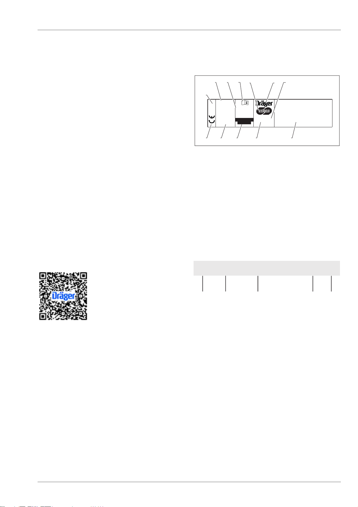
INFO: Never apply decals and/or identification labels less than
25 mm from the edges of the helmet shell.
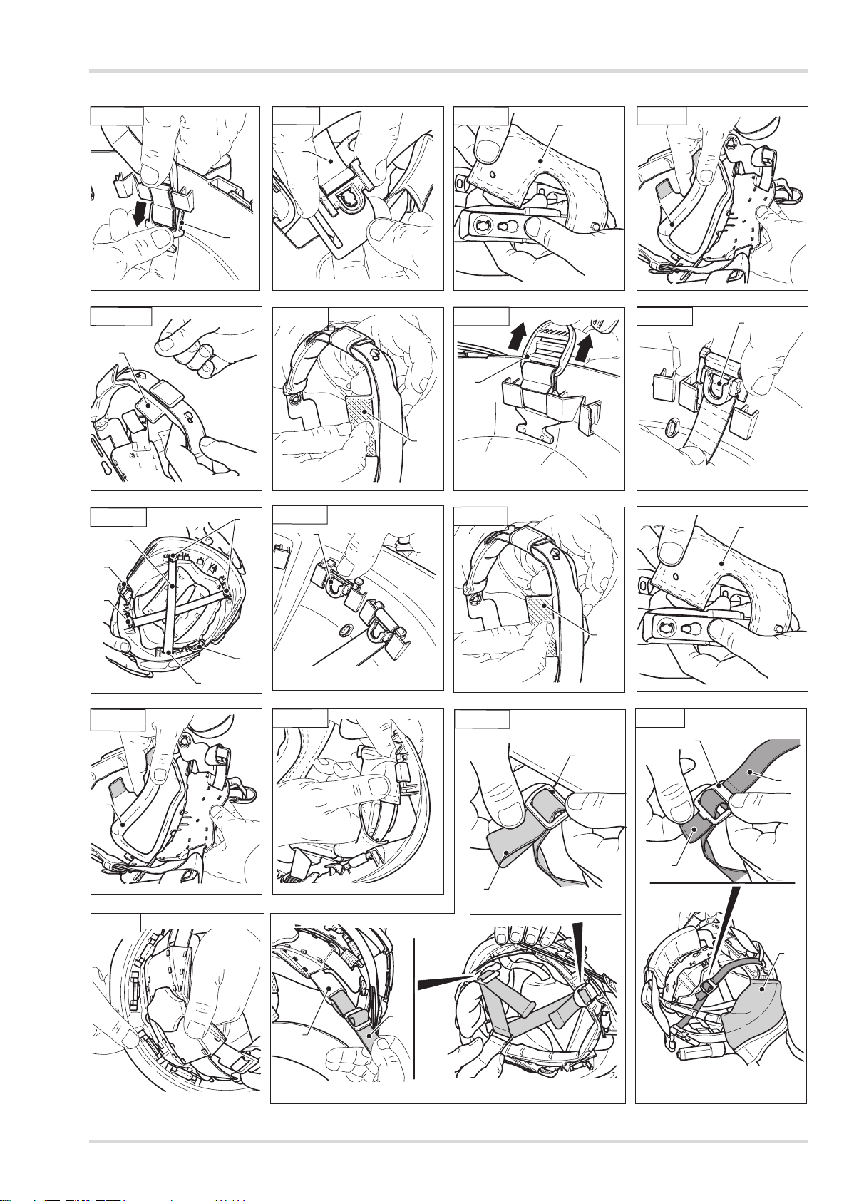
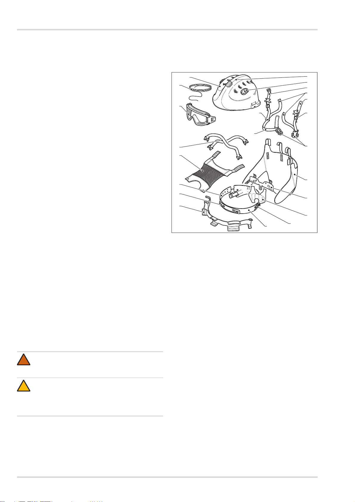
5.3.1 Disassembling the helmet
To proceed with disassembly, place the helmet upside down on
an uncluttered surface in order not to lose any components.
During the disassembly procedures, position all the parts
removed in an orderly way.
1. Pull the strap (item 1, see figure 4.3.1 a) out of the
adjusters (item 2) and out of the anti-creep system.
2. Release the rear part (item 3, see figure 4.3.1 b) of the
protective mesh (item 4, see figure 4.3.1 c).
3. Release the two tabs (item 5, see figure 4.3.1 d) of the
harness (item 6).
4. Release the rear of the harness (item 6, see figure 4.3.1 e)
by pulling upwards so that the clips are released from the
helmet shell.
5. Release the front part (item 7, see figure 4.3.1 f) of the
harness and pull it upwards so that the clips are released
from the helmet shell, then remove the harness from the
helmet (see figure 4.3.1 g).
6. Release the retention system by pushing the fasteners
(item 8, see figure 4.3.1 h) downward and remove the
harness with the retention system.
7. Unfasten the clips (item 9, see figure 4.3.1 i) from the
harness (turn and remove).
8. Remove the mesh (item 4, see figure 4.3.1 k) releasing it
from the respective fastening pins.
9. Release and remove the rear comfort piece (item 10, see
figure 4.3.1 l) by unfastening the hook-and-loop strips.
10. Remove the front comfort piece by unfastening the hook-
and-loop strips (item 11, see figure 4.3.1 m+n).
5.3.2 Assembling the helmet
1. Refit the fasteners (item 1, see figure 4.3.2 a) of the
retention system from the bottom to the top.
2. Fit the clips (item 2, see figure 4.3.2 b) of the anti-shock
straps (item 3, see figure 4.3.2 c) making sure that the
strap passes between the clips and the external shell and
refasten the clips (item 4, see figure 4.3.2 d).
3. Fit the front comfort piece (item 5, see figure 4.3.2 e) on
the retention system.
4. Refit the mesh (item 6, see figure 4.3.2 f) on the harness.
5. Refit the rear comfort piece (item 7, see figure 4.3.2 g)
using the hook-and-loop strips.
6. Refit the harness complete with mesh and comfort piece on
the helmet and fasten the rear and front fasteners (see
figure 4.3.2 h+i).
7. Fit the retention system inserting the front straps (item 8,
see figure 4.3.2 k) in the adjusters (item 9) and the rear
straps (item 10) in the anti-creep system (item 11).
8. Fit the anti-stretch strap (item 12, see figure 4.3.2 l) of the
retention system using the anti-creep adjuster (item 13).
The anti-stretch strap (item 12) stays positioned underneath
the protective mesh (item 14).
6 Transport
The helmet can be transported in the original packaging or the
optional helmet bag.
CAUTION
Never use abrasive or strong alkaline detergents,
solvents or organic liquids such as petrol or alcohol!
Otherwise the break strength and thus, the protective
function of the helmet will be decreased.
CAUTION
Never use abrasive or strong alkaline detergents,
solvents or organic liquids such as petrol or alcohol!
Otherwise the break strength and thus, the protective
function of the helmet, will be decreased.
!
!

Storage
Dräger HPS 3500 11
7 Storage
The helmet must be stored in a clean, dry, dark place away
from sources of heat and at a temperature between +10 °C
and +40 °C.
The helmet and its accessories can either be stored in the
original transport packaging or in the optional transportation
bag.
Never leave the helmet in a vehicle if not in its bag to prevent
needless exposure to the sun (UV rays).
8 Disposal
With proper care, both helmet and goggles have a life time of
about 8 years. Depending on the conditions of use, the life time
may vary considerably. The helmet must be disposed of if
damaged or stressed. Dispose of the goggles if there is evident
surface damage, such as scratches, cuts or marks.
Strictly comply with the disposal regulations in force.
9 Technical data
10 Order list
Helmet weight
HPS 3500 Basic
(mass dyed versions)
ca.710g(±3%)
HPS 3500 Premium
(painted versions)
ca.780g(±3%)
Goggles weight ca. 116 g
Helmet dimensions (W x H x L) 240 x 295 x 193 mm
Storage temperature +10 °C to +40 °C
Designation and description Order number
Helmet shell with ventilation system and
adaptors - red R58407
Helmet shell with ventilation system and
adaptors - white R58408
Helmet shell with ventilation system and
adaptors - yellow R58409
Helmet shell with ventilation system and
adaptors - blue R58410
Helmet shell with ventilation system and
adaptors - black R58411
Helmet shell with ventilation system and
adaptors - luminescent R58412
Helmet shell with ventilation system and
adaptors - bright yellow R58449
Helmet shell with ventilation system and
adaptors - bright orange R58560
Ventilation system R58413
Adaptors / Lamp holder snap-on R58565
Suspension system R62664
Chin strap R62665
Suspension mesh R58418
Size adjustment system R62666
Adjustment wheel R62668
Rear adjuster R62667
Front band R58421
Front comfort piece R58422
Rear comfort piece R58423
Silicone cord R58425
Elastic band - variable R58562
Safety goggles1with elastic band R58564
Safety goggles1with silicone band R58424
Reflective strips - red1R58426
Reflective strips - yellow1R58427
Reflective strips - grey-silver1R58428
Lamp holder (Parat)1R58566
Lamp holder (UK-Peli)1R62669
Helmet lamp Dräger PX1 LED1R62350
Earmuffs1R58430
Mesh visor1R58431
Polycarbonate visor1R58432
Polycarbonate visor (spark resistant)1R58433
Neck guard1R58434
Helmet pouch1R79282
Helmet bag, big1R58555
Helmet bag, small1R68555
1 optional
Designation and description Order number

12 Dräger HPS 3500
Sicherheitsbezogene Informationen
1 Sicherheitsbezogene
Informationen
Diese Gebrauchsanweisung und die
Gebrauchsanweisungen von zugehörigen Produkten vor
Verwendung des Produkts sorgfältig lesen.
Gebrauchsanweisung beachten. Der Benutzer muss die
Anweisungen genau verstehen und beachten. Das
Produkt ist nur für die im Abschnitt „Verwendungszweck“
beschriebene Verwendung bestimmt.
Die Gebrauchsanweisung nicht entsorgen. Sicherstellen,
dass sie aufbewahrt und vom Benutzer des Produkts
entsprechend verwendet wird.
Alle auf das Produkt bezogenen lokalen und nationalen
Regeln und Vorschriften beachten.
Inspektionen, Instandsetzungen und Reparaturen sind
ausschließlich von ausgebildetem Fachpersonal
durchzuführen. Wir empfehlen, einen Servicevertrag mit
Dräger abzuschließen, und alle Instandsetzungen,
Wartungs- und Reparaturarbeiten durch Dräger
durchführen zu lassen.
Zur Instandhaltung nur Original-Dräger-Ersatzteile
und -Zubehör verwenden. Die ordnungsgemäße Funktion
des Produkts kann sonst eingeschränkt werden.
Keine fehlerhaften oder unvollständigen Produkte
verwenden. Das Produkt nicht verändern. Im Produkt
dürfen keine Komponenten von Drittanbietern verwendet
werden.
Im Fall einer Störung oder eines Ausfalls eines Produkts
oder einer Komponente Dräger informieren.
Durch falsche Innenausstattungen, Innenausstattungen
von Drittanbietern, das Bohren neuer Löcher für Zubehör
oder sonstige Modifikationen am Helm kann die
Schutzwirkung beeinträchtigt und eine Zulassung ungültig
werden.
Wird er mit weiterer persönlicher Schutzausrüstung oder
Zubehör ausgestattet, das nicht vom Helmhersteller zur
Verwendung mit diesem Helm bereitgestellt wurde, kann
ein der europäischen Norm entsprechender Helm unter
Umständen nicht mehr alle Klauseln dieser europäischen
Norm erfüllen.
Der Helm erfüllt die Anforderungen der europäischen
Normen, wenn der vom Helmhersteller bereitgestellte
Kinnriemen gemäß dieser Anleitung getragen und
angepasst wird.
2 Konventionen in diesem Dokument
Bedeutung der Warnzeichen
Die folgenden Warnzeichen werden in diesem Dokument
verwendet, um die zugehörigen Warntexte zu kennzeichnen
und hervorzuheben, die eine erhöhte Aufmerksamkeit seitens
des Anwenders erfordern. Die Bedeutungen der Warnzeichen
sind wie folgt definiert:
3 Beschreibung
3.1 Produktübersicht
1 Helmschale
2 Belüftungssystem
3 Adapter
4 Schutzbrille (optional)
5 Halteband
6 Polsterung Tragering
7 Nackenpolsterung
8 Stoßdämpfungsbänder
9 Rastung (vorne)
10 Tragering
11 Haarnetz
12 Verstellsystem
13 Rastung (hinten)
14 Justierband
15 Kinnriemen
16 Nackenbänder
17 Schläfenbänder
18 Ring, einfach
19 Steckschnalle
20 Schutzriemen
21 Nackenschutz (optional)
WARNUNG
Hinweis auf eine potenzielle Gefahrensituation.
Wenn diese nicht vermieden wird, können Tod oder
schwere Verletzungen eintreten.
!
VORSICHT
Hinweis auf eine potenzielle Gefahrensituation. Wenn
diese nicht vermieden wird, können Verletzungen oder
Schädigungen am Produkt oder der Umwelt eintreten.
Kann auch als Warnung vor unsachgemäßem Ge-
brauch verwendet werden.
!
00131261
1
4
5
2
3
18
20
16
20
17
19
15
8
11
10
9
6
21
13
7
12
14

Beschreibung
Dräger HPS 3500 13
3.2 Helmbeschreibung
Der Helm ist für die Kopfgrößen 52 bis 64 cm stufenlos
einstellbar und mit einem Belüftungssystem ausgestattet, das
das Eindringen von Funken, Spänen und anderen Partikeln
verhindert. Darüber hinaus können die Belüftungsöffnungen
im Einsatz auch vollständig geschlossen werden.
Der Helm kann mit einer Schutzbrille ausgestattet werden.
Alternativ kann auch ein Drahtgittervisier mit dem Helm
verwendet werden. Als Helmzubehör erhältlich sind u. a.
Nackenschutz, Lampenhalter, Gehörschutz und Reflexstreifen.
3.3 Verwendungszweck
Der Dräger HPS 3500 ist speziell für die Anforderungen von
Notfall-Einsatzteams bei Such-, Rettungs- und
Bergungsarbeiten (EN 16473:2014), in der Wald- und
Buschbrandbekämpfung (EN 16471:2014), in der
Höhenrettung (EN 12492:2012), der Wasserrettung
(EN 1385:2012) sowie bei technischer Hilfeleistung jeglicher
Art entwickelt worden.
Der Helm ist so konzipiert, dass er Aufprallenergie absorbiert,
wodurch Helmschale oder Bänderung u. U. auch teilweise
beschädigt werden können. Auch wenn solche Schäden nicht
unmittelbar sichtbar sind, sind Helme, die einer hohen
Einwirkung ausgesetzt waren, zu ersetzen.
3.4 Einschränkungen des Verwendungszwecks
Der Dräger HPS 3500 ist weder zur Verwendung als Fahrrad-
oder Motorradhelm noch als Feuerwehrhelm gemäß
EN 443:2008 bestimmt.
3.5 Zulassungen
Der Helm ist zugelassen nach
EN 16471:2014
EN 16473:2014
EN 12492:2012
EN 1385:2012
CA 39767
(EU) 2016/425
Konformitätserklärung:
siehe https://www.dropbox.com/sh/q3m2u6z6kmk3qyk/
AABic12zkRYaV2_LsjnA9dTga?dl=0
Die optionale Schutzbrille ist zugelassen nach
EN 166:2001
EN 167:2001
EN 168:2001
EN 14458:2004
3.6 Erklärung der Kennzeichnungen und
Symbole an Helm und Schutzbrille
3.6.1 Helm
1 Hersteller
2 Siehe Gebrauchsanweisung
3Größen
4 Zusätzliche Anforderungen (Markierung mit ***)
5 Benannte Stelle
6CE-Zeichen
7 Normen und Standards
8 Hergestellt in, Herstelldatum
9 Seriennummer
10 Produktbeschreibung
11 Produktname
12 Inverkehrbringer
3.6.2 Schutzbrille (optional)
Brille (EN 166)
1 Schutzstufe
2 Hersteller
3 Kennzeichnungen
1: Optische Klasse
B: Beständigkeit gegen Hochgeschwindigkeitspartikel –
durchschnittliche Aufprallenergie
9: Beständigkeit gegen Schmelzmetall und heiße
Festkörper
K: Beständigkeit gegen Beschädigung durch Feinstaub
N: Beständigkeit gegen Beschlagen
4CE-Zeichen
5 Benannte Stelle
52~64 cm
Casco per Alpinisti
Bergsteigerhelme
Helmet for mountainner
Casque d’Alpinistes
Capacetes para alpinistas
Cascos para montñeros
Größen - Taglie
Size - Tamanhos
Tamaños - Tailles
SICUREZZA COMPAGNIERIUNITE
Elmo per il soccorso tecnico
Helmet for technical rescue
Helme für technische Rettung
Casque pour les opérations
de secours technique
Casco para rescate tecnico
Capacete para resgate técnico
Elmo per antincendio boschivo
Helmets for wildland fire fighting
Helme für Wald-
und Flächenbrandbekämpfung
Casques pour la lutte contre les
feux d’espaces naturels
Casco de incendios forestales
0497
EN 16471:2014
EN 16473:2014
EN 12492:2012
Made in Italy
DD/MM/YY
HPS 3500
sn. xxxxxx
EN 1385:2012
CA 39767
-30°C
1234
5
6 7 8 9 10
11
01531261
12
01431261
SICOR2-1.2 1 B 9 K N
CE
12 3 45
0497

14 Dräger HPS 3500
Gebrauch
Gestell (EN 166)
1 Normen und Standards
2 Hersteller
3 Kennzeichnungen
B: Beständigkeit gegen Hochgeschwindigkeitspartikel –
durchschnittliche Aufprallenergie
3: Beständigkeit gegen Flüssigkeitstropfen und Spritzer
4: Beständigkeit gegen große Staubteilchen
5: Beständigkeit gegen Gase und Feinstaub
9: Beständigkeit gegen Schmelzmetall und heiße
Festkörper
K: Beständigkeit gegen Beschädigung durch Feinstaub
4CE-Zeichen
5 Benannte Stelle
Brille (EN 14458)
1 Normen und Standards
2 Hersteller
3 Produktname
4 Herstellungsjahr
5 Feuerwehr-Symbol
6 Augensymbol
7 Abriebfestigkeit
8 Beständigkeit gegen Schleierbildung
9 Elektrische Eigenschaften
10 Verweis auf Gebrauchsanweisung
4Gebrauch
4.1 Voraussetzungen für den Gebrauch
Bei unsachgemäßer Verwendung des Helms, die nicht dem
Verwendungszweck bzw. geltenden Vorschriften und
Verordnungen entspricht, besteht Verletzungsgefahr.
Um dem Träger ausreichenden Schutz zu bieten, muss der
Helm der jeweiligen Kopfgröße angepasst werden.
Zu Ihrer eigenen Sicherheit sollten Sie sich mit dem
Verstellsystem vertraut machen, bevor Sie den Helm
verwenden. Nehmen Sie verschiedene Einstellungen vor,
passen Sie das Haltesystem an und lösen Sie es mehrmals, so
dass die Handhabung zur Routine wird.
4.2 Vorbereitungen für den Gebrauch
4.2.1 Tragehöhe einstellen
Die Tragehöhe durch Anpassen des Haarnetzes wie folgt
einstellen:
1. Rückseitige Laschen des mit Klettverschluss befestigten
Haarnetzes lösen und durch die Schlitze der Bänderung
schieben.
4.2.2 Helm dem Kopfumfang des Trägers anpassen
INFO: Im ausgelieferten Zustand ist der Tragering, der auf den
Kopfumfang des Trägers eingestellt werden kann, voll
ausgezogen. Den Tragering wie nachstehend beschrieben
einstellen.
1. Helm aufsetzen und die Größe dann mit dem Rad
einstellen.
2. Es wird empfohlen, mit einer Hand auf den Helm zu
drücken und die Einstellung mit der anderen Hand
vorzunehmen. Die Größeneinstellung wirkt auch auf die
Nackenbänder.
3. Die zwei Riemen (Nr. 1, siehe Abbildung 3.2.2) zwischen
Kinnriemen und Einstellsystem nur bei der ersten
Anpassung ziehen.
4.2.3 Haltesystem anpassen
Erster Gebrauch
Kinnriemen:
1. Höhe wie in Kapitel 3.2.1 beschrieben einstellen.
2. Helm aufsetzen.
3. Größe wie in Kapitel 3.2.2 beschrieben einstellen.
4. Schnalle schließen.
5. Den Einstellriemen (Nr. 1, siehe Abbildung 3.2.3 a) in das
Querteil des Systems (Nr. 2) schieben.
6. Einstellriemen erneut ziehen, so dass das System richtig
angepasst ist.
7. Lässt sich das System nicht richtig anpassen, zur
Anpassung die Schnallen (Nr. 3, siehe Abbildung 3.2.3 b)
auf beiden Seiten des Kinnriemens verwenden oder den
Riemen länger oder kürzer einstellen.
Regulärer Gebrauch
Kinnriemen:
1. Kinnriemen festziehen und Schnalle schließen.
Größe anpassen und Einstellsystem anpassen:
1. Einstellungen wie in Kapitel 3.2.2 beschrieben vornehmen.
01331261
SICOR 0497
CE
1345
B 3 4 5 9 K
EN166
2
00531261
EN 14458 SICOR WFG02 aa + K N
Ω
12 345678910
WARNUNG
Verletzungsgefahr!
Die Schutzwirkung des Helms wird nur erreicht, wenn
der Helm perfekt sitzt, Tragehöhe, Bänderung und
Tragering richtig eingestellt sind und der Kinnriemen
geschlossen ist. Helm nur tragen, wenn er vollständig
zusammengebaut ist. Jegliche zusätzlichen Teile
müssen ordnungsgemäß am Helm befestigt sein.
Abnehmbare Teile nicht einzeln tragen.
!

Gebrauch
Dräger HPS 3500 15
4.2.4 Schutzbrille (optional) befestigen
Brille mit Silikonband (siehe Abbildung 3.2.4 c)
1. Ein Ende des Silikonbands in die Aufnahme (Nr. 1)
einführen und einen Knoten machen (Detail A).
2. Halteband durch die Helminnenseite (Nr. 2) führen und in
die Aufnahmen am Brillengestell (Nr. 3) einführen. Darauf
achten, dass die Schutzbrille richtig herum aufgesetzt wird!
3. Halteband erneut durch die Helminnenseite (Nr. 2) zur
Helmschalenaußenseite und dann wieder in den
Helminnenbereich (Nr. 4) führen.
4. Halteband durch die Aufnahmen am Brillengestell (Nr. 3) und
dann wieder durch den Helminnenbereich (Nr. 4) führen.
5. Das Halteband abschließend durch die Aufnahme (Nr. 5)
führen und mit einem Knoten sichern (Detail A).
Brille mit Elastikband (siehe Abbildung 3.2.4 d)
1. Ein Ende des Elastikbands in die schräge Anschlussstelle
der Helmschalenaußenseite (Detail B) einführen.
2. Elastikband auf den hinteren Umfang der Schale schieben.
3. Das andere Ende des Elastikbands in die schräge
Anschlussstelle auf der anderen Seite der Helmschale
einführen.
4. Elastikband in die beiden Löcher der seitlichen Befestigung
der Schutzbrille einführen und fixieren.
Die Schutzbrille kann, wenn sie nicht benötigt wird, auch
einfach oben auf dem Helm getragen werden (siehe
Abbildung 3.2.4 b).
Der Druck der Schutzbrille auf das Gesicht lässt sich durch
Ändern der Haltebandlänge anpassen.
4.2.5 Lampe (optional) befestigen
Der Lampenhalter wird links oder rechts an der Außenschale
an dem speziellen Adapter angebracht.
1. Zum Verwenden der Lampe zunächst den Halter (Nr. 1,
siehe Abbildung 3.2.5 a) in den Adapter (Nr. 2) schieben.
2. Lampe (Nr. 3, siehe Abbildung 3.2.5 c) am Lampenhalter
(Nr. 1) anbringen.
Die Lampe kann in zwei Richtungen ausgerichtet sein:
nach unten (siehe Abbildung 3.2.5 d)
nach oben (siehe Abbildung 3.2.5 e)
4.2.6 Gehörschutzkapseln (optional) befestigen
1. Zum Befestigen der Gehörschutzkapseln zunächst die
Halterungen (Nr. 2, siehe Abbildung 3.2.6 a) auf den
Vorrichtungen (Nr. 1) an der Außenschale anbringen.
2. Die Gehörschutzkapseln über die Ohren ziehen oder bei
Nichtverwendung nach oben schieben.
3. Um sie nach oben auf die Helmschale zu schieben, die
Gehörschutzkapseln zunächst von den Ohren ziehen, bis
ein Klicken zu hören ist. Dann nach oben drehen und durch
Drücken einrasten lassen.
4. Um die Gehörschutzkapseln zu entfernen, auf den
Verriegelungspunkt (Nr. 3, siehe Abbildung 3.2.6 e) der
Halterung (Nr. 2) drücken.
4.2.7 Drahtgittervisier/PC-Visier/Elektrovisier (optional)
anbringen
INFO: Um dieses Zubehör anbringen zu können, müssen die
Gehörschutzkapseln bzw. entsprechenden Halterungen
angebracht sein.
Dieses Zubehör kann nicht zusammen mit der Schutzbrille
verwendet werden.
1. Visier auf die Befestigungsclips (Nr. 1, siehe
Abbildung 3.2.7 a) an den Halterungen (Nr. 2) klicken.
Das angebrachte Visier kann wie folgt getragen werden:
unten (siehe Abbildung 3.2.7 c)
oben (siehe Abbildung 3.2.7 b)
2. Das Visier wird entfernt, indem es aus den
Befestigungsclips gezogen wird.
4.2.8 Nackenschutz (optional) anbringen
1. Die zwei Laschen (Nr. 1, siehe Abbildung 3.2.8 a) der
Bänderung lösen.
2. Die Rückseite der Bänderung (Nr. 1, siehe Abbildung 3.2.8 b)
lösen; hierfür nach oben ziehen und von den Clips der
Helmschale (Nr. 2, siehe Abbildung 3.2.8 c) trennen.
3. Die zwei mittigen Riemen (Nr. 3, siehe Abbildung 3.2.8 d)
in die Laschen der zwei Clips (Nr. 4) einführen und wieder
fest anbringen (siehe Abbildung 3.2.8 e).
4. Rückseitige Bänderung wieder anbringen.
5. Die zwei Seitenbänder (Nr. 5, siehe Abbildung 3.2.8 f) des
Bänderungstragerings anbringen.
Zum Entfernen des Nackenschutzes in umgekehrter
Reihenfolge vorgehen.
Der Nackenschutz kann auf zwei Arten Schutz bieten:
Nacken- und Schulterschutz:
Hierfür den Nackenschutz so hinter dem Nacken und
auf den Schultern platzieren, dass die Seitenteile
zurückgeschlagen sind (siehe Abbildung 3.2.8 g).
Nacken-, Schulter- und Halsschutz:
Hierfür den Nackenschutz so hinter dem Nacken und
auf den Schultern platzieren, dass die Seitenteile um
den Halsbereich geschlagen sind (siehe
Abbildung 3.2.8 h).
4.3 Im Einsatz
4.3.1 Belüftungssystem verwenden
Das Belüftungssystem kann geschlossen werden, sodass kein
Regen- oder Löschwasser in den Helm eindringen kann. Auch
bei Verwendung eines Schutzgitters empfiehlt Dräger, das
Belüftungssystem in Brandbekämpfungseinsätzen oder bei
starkem Wind vollständig zu schließen. Wird der Helm bei der
Wasserrettung eingesetzt, empfiehlt Dräger, das
Belüftungssystem zu öffnen.
1. Hierfür den Einstellhebel oben auf dem Helm mit einer
Hand betätigen (siehe Abbildung 3.3.1).
Position 1 = Geschlossen
Position 2 = Offen

16 Dräger HPS 3500
Wartung
5 Wartung
5.1 Instandhaltungsintervalle
Den Helm vor und nach jedem Einsatz prüfen. Dabei
besonders alle Befestigungspunkte kontrollieren (Bänderung
und Haltesystem). Verschlissene bzw. beschädigte Teile sofort
auswechseln; dabei ausschließlich Ersatzteile von Dräger
verwenden, da nur Original-Ersatzteile speziell für die
Verwendung mit dem Helm konzipiert sind.
Helmschale und Bänderung auf Verfärbungen bzw. Risse o. Ä.
überprüfen.
Helm und Aufnahmen auf Risse, Bruchstellen o. Ä. überprüfen.
Haltesystem (Nähte!) auf einwandfreien Zustand überprüfen.
Sicherheitsbrille auf Kratzer und Beschädigungen überprüfen.
5.2 Reinigung
5.2.1 Helm reinigen
Den Helm nach dem Einsatz immer im Tragebeutel oder an
einem abgeschlossenen Ort (z. B. im Spind), vor Sonnenlicht
und Feuchtigkeit geschützt, aufbewahren.
Den Helm wie folgt reinigen:
Den Helm niemals in der direkten Sonne reinigen.
Helm zerlegen (siehe Kapitel 5.3.1 auf Seite 16).
Die einzelnen inneren und äußeren Helmteile mit neutraler
Seife und lauwarmen Wasser reinigen.
Anschließend bei Raumtemperatur trocknen lassen.
Nicht trocknergeeignet!
Vor dem Zusammenbau sicherstellen, dass alle Teile
vollständig trocken sind.
Ist dies der Fall, Helm wieder zusammenbauen (siehe
Kapitel 5.3.2 auf Seite 16).
5.2.2 Schutzbrille reinigen
Die Schutzbrille wie folgt reinigen:
Die Schutzbrille niemals in der direkten Sonne reinigen.
Schutzbrille vom Helm abnehmen.
Die Gläser mit normalem Reinigungsmittel reinigen.
Mit einem weichen Tuch, am besten Mikrofasertuch
abtrocknen.
5.3 Wartungsarbeiten
INFO:
Etiketten bzw. Aufkleber zur Kennzeichnung nur in einem
Abstand von mindestens 25 mm vom Helmschalenrand
anbringen.
5.3.1 Helm zerlegen
Zum Zerlegen den Helm zunächst umgedreht auf eine
saubere und freie Oberfläche legen, so dass keine Helmteile
verloren gehen.
Während der Demontage alle Helmteile geordnet
nebeneinander legen.
1. Riemen (Nr. 1, siehe Abbildung 4.3.1 a) aus den Schnallen
(Nr. 2) ziehen und vom Einstellsystem lösen.
2. Den hinteren Teil (Nr. 3, siehe Abbildung 4.3.1 b) des
Schutzgitters (Nr. 4, siehe Abbildung 4.3.1 c) lösen.
3. Die zwei Laschen (Nr. 5, siehe Abbildung 4.3.1 d) der
Bänderung (Nr. 6) lösen.
4. Die Rückseite der Bänderung (Nr. 6, siehe
Abbildung 4.3.1 e) lösen; hierfür nach oben ziehen und von
den Clips der Helmschale trennen.
5. Den vorderen Teil (Nr. 7, siehe Abbildung 4.3.1 f) der
Bänderung lösen und nach oben ziehen, bis die Clips von
der Helmschale gelöst sind. Dann die Bänderung aus dem
Helm entfernen (siehe Abbildung 4.3.1 g).
6. Das Haltesystem lösen; hierfür die Verschlüsse (Nr. 8,
siehe Abbildung 4.3.1 h) nach unten drücken und dann
Bänderung und Haltesystem ausbauen.
7. Die Clips (Nr. 9, siehe Abbildung 4.3.1 i) von der
Bänderung lösen (drehen und entfernen).
8. Gitter (Nr. 4, siehe Abbildung 4.3.1 k) ausbauen; es hierfür
von den Haltestiften lösen.
9. Klettstreifen lösen und die Nackenpolsterung (Nr. 10, siehe
Abbildung 4.3.1 l) entfernen.
10. Die Polsterung des Tragerings entfernen; hierfür die
Klettstreifen (Nr. 11, siehe Abbildung 4.3.1 m+n) lösen.
5.3.2 Helm zusammenbauen
1. Verschlüsse (Nr. 1, siehe Abbildung 4.3.2 a) des
Haltesystems von unten nach oben wieder anbringen.
2. Clips (Nr. 2, siehe Abbildung 4.3.2 b) der Halteriemen
(Nr. 3, siehe Abbildung 4.3.2 c) anbringen; dabei darauf
achten, dass der Riemen zwischen den Clips und der
Außenschale hindurch geführt wird. Dann die Clips (Nr. 4,
siehe Abbildung 4.3.2 d) wieder befestigen.
3. Die Polsterung des Tragerings (Nr. 5, siehe
Abbildung 4.3.2 e) am Haltesystem anbringen.
4. Das Gitter (Nr. 6, siehe Abbildung 4.3.2 f) wieder an der
Bänderung anbringen.
5. Die Nackenpolsterung (Nr. 7, siehe Abbildung 4.3.2 g)
wieder mit den Klettstreifen befestigen.
6. Die vollständige Bänderung mit Gitter und Polsterung
wieder am Helm anbringen; dann die Verschlüsse hinten
und vorne schließen (siehe Abbildung 4.3.2 h+i).
7. Dann das Haltesystem anbringen; hierfür die vorderen
Riemen (Nr. 8, siehe Abbildung 4.3.2 k) in die Schnallen
(Nr. 9) und die hinteren Riemen (Nr. 10) in das
Einstellsystem (Nr. 11) einführen.
8. Den Schutzriemen (Nr. 2, siehe Abbildung 4.3.2 l) des
Haltesystems mit den Schläfenbändern (Nr. 13) anbringen.
Der Schutzriemen (Nr. 12) bleibt unter dem Schutzgitter
(Nr. 14).
VORSICHT
Zum Reinigen keine scheuernden oder scharfen
alkalischen Reinigungsmittel, Lösungsmittel oder
organischen Flüssigkeiten wie Benzin oder Alkohol
verwenden!
Andernfalls nimmt die Bruchfestigkeit ab, was die
Schutzfunktion beeinträchtigt.
VORSICHT
Zum Reinigen keine scheuernden oder scharfen
alkalischen Reinigungsmittel, Lösungsmittel oder
organische Flüssigkeiten wie Benzin oder Alkohol
verwenden!
Andernfalls nimmt die Bruchfestigkeit ab, was die
Schutzfunktion beeinträchtigt.
!
!

Transport
Dräger HPS 3500 17
6 Transport
Der Helm kann in der Originalverpackung oder in einem
optionalen Transportbeutel transportiert werden.
7 Lagerung
Den Helm an einem sauberen, trockenen, dunklen Ort ohne
Hitzequellen und bei einer Temperatur von +10 °C und +40 °C
lagern.
Helm und Zubehör können entweder in der Original-
Transportverpackung oder in einem optionalen
Transportbeutel gelagert werden.
Um den Helm vor Sonnenlicht (UV-Strahlen) zu schützen,
diesen nur in seinem Beutel in einem Fahrzeug liegenlassen.
8Entsorgung
Bei entsprechender Pflege und Handhabung haben Helm und
Schutzbrille eine Nutzungsdauer von ca. 8 Jahren. Je nach
Einsatzbedingungen kann die Lebensdauer stark variieren.
Bei Beschädigungen ist der Helm zu entsorgen. Schutzbrille
bei offensichtlichen Oberflächenbeschädigungen wie
Kratzern, Schrammen o. Ä. entsorgen.
Bei der Entsorgung die jeweils geltenden Vorschriften
beachten.
9 Technische Daten
10 Bestellliste
Helmgewicht
HPS 3500 Basic
(gefärbte Versionen) ca. 710 g (±3 %)
HPS 3500 Premium
(lackierte Versionen) ca. 780 g (±3 %)
Schutzbrillengewicht ca. 116 g
Helmabmessungen (B x H x L) 240 x 295 x 193 mm
Lagertemperatur +10 °C bis +40 °C
Benennung und Beschreibung Bestellnummer
Helmschale mit Belüftungssystem und
Adaptern – rot R58407
Helmschale mit Belüftungssystem und
Adaptern – weiß R58408
Helmschale mit Belüftungssystem und
Adaptern – gelb R58409
Helmschale mit Belüftungssystem und
Adaptern – blau R58410
Helmschale mit Belüftungssystem und
Adaptern – schwarz R58411
Helmschale mit Belüftungssystem und
Adaptern – nachleuchtend R58412
Helmschale mit Belüftungssystem und
Adaptern – leuchtend gelb R58449
Helmschale mit Belüftungssystem und
Adaptern – leuchtend orange R58560
Belüftungssystem R58413
Adapter / aufsteckbarer Lampenhalter R58565
Haltesystem R62664
Kinnriemen R62665
Haarnetz R58418
Verstellsystem R62666
Stellrad R62668
Hinterer Tragering R62667
Tragering R58421
Polsterung Tragering R58422
Nackenpolsterung R58423
Silikonband R58425
Elastikband – variabel R58562
Schutzbrille1mit Elastikband R58564
Schutzbrille1mit Silikonband R58424
Reflexstreifen – rot1R58426
Reflexstreifen – gelb1R58427
Reflexstreifen – grau-silber1R58428
Lampenhalter (Parat)1R58566
Lampenhalter (UK-Peli)1R62669
Helmlampe Dräger PX1 LED1R62350
Gehörschutzkapseln1R58430
Drahtgittervisier1R58431
PC (Polycarbonat)-Visier1R58432
PC (Polycarbonat)-Visier
(funkenbeständig)1R58433
Nackenschutz1R58434
Transportbeutel1R79282
Transporttasche1, groß R58555
Transporttasche1, klein R68555
1 optional
Benennung und Beschreibung Bestellnummer

18 Dräger HPS 3500
Consignes de sécurité
1 Consignes de sécurité
Avant d'utiliser ce produit, lire attentivement la présente
notice d'utilisation et celle des produits connexes.
Respecter la notice d'utilisation à la lettre. L'utilisateur doit
comprendre la totalité des instructions et les respecter de
façon rigoureuse. N'utiliser ce produit qu'aux fins
spécifiées dans le chapitre Utilisation prévue de ce
document.
Ne pas jeter la notice d'utilisation. S'assurer qu'elle est
conservée et que l'utilisateur du produit l'utilise de façon
appropriée.
Respecter la réglementation et toutes les règles locales
associées à ce produit.
Seul un personnel formé et compétent est autorisé à
inspecter, à réparer et à entretenir le produit. Dräger
recommande un contrat de service Dräger pour toutes les
activités de maintenance et que toutes les réparations
soient effectuées par Dräger.
N'utiliser que des pièces détachées et des
accessoires originaux Dräger pour la maintenance. Sinon,
cela pourrait nuire au bon fonctionnement du produit.
Ne pas utiliser un produit défectueux ou incomplet. Ne pas
modifier le produit. Des composants provenant d'un tiers
ne doivent pas être fixés au produit.
Aviser Dräger en cas de toute panne ou de tout défaut du
produit ou de ses composants.
Les mauvais composants intérieurs ou ceux provenant
d'un tiers, le perçage de nouveaux trous pour des
accessoires ainsi que d'autres modifications apportées au
casque peuvent nuire à la fonction de protection et
annulent l'homologation.
S'il est équipé d'une autre partie d'équipement de
protection individuelle ou d'un accessoire autre que ceux
fournis par le fabricant du casque et devant être utilisé avec
ce casque, un casque certifié conforme à cette norme
européenne pourrait ne plus satisfaire à toutes les clauses
de cette norme européenne.
Ce casque est conforme aux exigences des normes
européennes lorsque la jugulaire fournie par le fabricant du
casque est portée et ajustée conformément à ces
instructions.
2 Conventions utilisées dans ce
document
Signification des symboles d'avertissement
Les symboles d'avertissement suivants sont utilisés dans ce
document pour signaler et mettre en relief les textes
d'avertissement associés auxquels l'utilisateur devra prêter
une attention soutenue. Les significations des symboles
d'avertissement sont définies de la façon suivante
3 Description
3.1 Aperçu du produit
1 Calotte externe
2 Système de ventilation
3 Adaptateurs
4 Lunettes de protection (en option)
5 Cordon
6 Matelassage avant
7 Matelassage arrière
8 Sangles amortisseur
9 Attaches avant
10 Bandeau
11 Filet de suspension
12 Système de réglage de la taille
13 Attache arrière
14 Bandeau de réglage
15 Jugulaire
16 Système contre le glissement
17 Boucle de réglage et de fermeture
18 Bague rectangulaire
19 Boucle à ouverture rapide
20 Courroie anti-étirement
21 Bavolet (en option)
3.2 Description des caractéristiques
Le casque est réglable à tout moment pour des tours de têtes
allant de 52 à 64 cm. Il est muni d'un système de ventilation qui
évite toute intrusion d'étincelles, de débris ou autres particules.
Les ouvertures de ventilation peuvent être complètement
fermées pendant une opération.
Le casque peut être pourvu de lunettes de protection.
Alternativement, une visière grillagée peut être fixée au
casque. Le bavolet, le porte-lampe, la protection auditive et les
bandes réfléchissantes sont disponibles comme accessoires.
AVERTISSEMENT
Signale une situation potentiellement dangereuse
qui, si elle n'est pas évitée, peut entraîner la mort ou
des blessures graves.
ATTENTION
Signale une situation potentiellement dangereuse. qui,
si elle n'est pas évitée, peut causer des blessures ou
des dommages matériels au produit ou à l'environne-
ment. Peut également être utilisé pour avertir d'une uti-
lisation incorrecte.
!
!
00131261
1
4
5
2
3
18
20
16
20
17
19
15
8
11
10
9
6
21
13
7
12
14

Description
Dräger HPS 3500 19
3.3 Utilisation prévue
Le Dräger HPS 3500 est conçu pour être utilisé uniquement
par des équipes d'urgence en mission de recherche et de
sauvetage (EN 16473:2014), pour la lutte contre les feux de
forêt et de broussailles (EN 16471:2014), le sauvetage en
hauteur (EN 12492:2012), le sauvetage en eau
(EN 1385:2012), et toutes opérations d'assistance et de
support technique dans des situations d'urgence.
Le casque a été conçu pour absorber l'énergie d'un impact en
détruisant ou en endommageant partiellement la calotte
externe du casque et le harnais. Même si le dommage n'est
pas immédiatement visible, tout casque qui a fait l'objet d'un
fort impact doit être remplacé.
3.4 Restrictions d'utilisation
Le Dräger HPS 3500 n'a pas non plus été conçu pour être
utilisé comme casque de vélo ou de moto ni comme casque de
pompier conforme à la directive EN 443:2008.
3.5 Approbations
Le casque est approuvé selon les directives
EN 16471:2014
EN 16473:2014
EN 12492:2012
EN 1385:2012
CA 39767
(UE) 2016/425
Déclaration de conformité:
voir https://www.dropbox.com/sh/q3m2u6z6kmk3qyk/
AABic12zkRYaV2_LsjnA9dTga?dl=0
Les lunettes de protection en option sont approuvées selon les directives
EN 166:2001
EN 167:2001
EN 168:2001
EN 14458:2004
3.6 Explication des marquages et symboles
d'identification
3.6.1 Casque
1 Fabricant
2 Consulter la notice d'utilisation
3 Tailles
4 Exigences optionnelles (marquées de ***)
5 Organisme d'homologation
6 Conformité européenne
7 Normes de référence
8 Pays et date de fabrication
9 Numéro de série
10 Description du produit
11 Nom du produit
12 Entité responsable de la mise sur le marché
3.6.2 Lunettes (en option)
Oculaire (EN 166)
1 Numéro classification
2 Identifiant du fabricant
3 Conformités :
1: Classe optique
B: Résistance aux particules à grande vitesse - énergie
d'impact moyenne
9: Résistance aux projections de métal en fusion et de
métal solide chaud
K: Résistance aux dommages aux fines particules de
poussière
N: Résistance à la buée
4 Conformité européenne
5 Organisme d'homologation
52~64 cm
Casco per Alpinisti
Bergsteigerhelme
Helmet for mountainner
Casque d’Alpinistes
Capacetes para alpinistas
Cascos para montñeros
Größen - Taglie
Size - Tamanhos
Tamaños - Tailles
SICUREZZA COMPAGNIERIUNITE
Elmo per il soccorso tecnico
Helmet for technical rescue
Helme für technische Rettung
Casque pour les opérations
de secours technique
Casco para rescate tecnico
Capacete para resgate técnico
Elmo per antincendio boschivo
Helmets for wildland fire fighting
Helme für Wald-
und Flächenbrandbekämpfung
Casques pour la lutte contre les
feux d’espaces naturels
Casco de incendios forestales
0497
EN 16471:2014
EN 16473:2014
EN 12492:2012
Made in Italy
DD/MM/YY
HPS 3500
sn. xxxxxx
EN 1385:2012
CA 39767
-30°C
1234
5
6 7 8 9 10
11
01531261
12
01431261
SICOR2-1.2 1 B 9 K N
CE
12 3 45
0497

20 Dräger HPS 3500
Utilisation
Cadre (EN 166)
1 Norme de référence
2 Identifiant du fabricant
3 Conformités :
1 : Classe optique
B : Résistance aux particules à grande vitesse - énergie
d'impact moyenne
3 : Résistance contre les gouttelettes et les éclaboussures
de liquide
4 : Résistance contre les grosses particules de poussière
5 : Résistance contre les gaz et les particules fines
9 : Résistance aux projections de métal en fusion et de
métal solide chaud
K : Résistance aux dommages aux fines particules de
poussière
4 Conformité européenne
5 Organisme d'homologation
Oculaire (EN 14458)
1 Norme de référence
2 Identifiant du fabricant
3 Nom du produit
4 Année de fabrication
5 Symbole pour l'utilisation par les pompiers
6 Symbole de la protection oculaire
7 Résistance à l'abrasion
8 Résistance à la formation de buée
9 Propriétés électriques
10 Référence de la notice d'utilisation
4 Utilisation
4.1 Conditions d'utilisation
Toute utilisation impropre du casque ou non conforme à
l'usage prévu ou aux lois et règlements applicables peuvent
exposer l'utilisateur à des blessures corporelles.
Afin de fournir une protection adéquate, ce casque doit être
ajusté au tour de tête de l'utilisateur.
Pour votre propre sécurité, familiarisez-vous avec les systèmes
de réglage avant d'utiliser le casque. Procéder à plusieurs
réglages et attacher, puis détacher le système de rétention
plusieurs fois afin que ces actions deviennent instinctives.
4.2 Préparation à l'utilisation
4.2.1 Ajuster la hauteur
Ajuster la hauteur du casque en changeant la profondeur du
filet de suspension comme suit :
1. Relâcher les languettes arrières du filet fermé par une
attache auto-agrippante et les glisser dans les fentes de la
bride.
4.2.2 Ajuster la circonférence
INFOS : Le casque est fourni avec la bandeau de réglage de
la taille complètement étendue. Pour un réglage adéquat,
suivre la séquence décrite plus bas.
1. Mettre le casque et ajuster ensuite la taille en utilisant la
molette.
2. Pour un réglage optimal, il est conseillé d'enfoncer le casque
vers le bas d'une main et d'ajuster de l'autre. Le système de
réglage de la taille agit aussi sur le système contre le
glissement.
3. Tirer les deux courroies (élément 1, voir figure 3.2.2) qui
relient la jugulaire au système contre le glissement,
uniquement lors du premier réglage.
4.2.3 Ajuster le système de rétention
Première utilisation
Jugulaire :
1. Ajuster en hauteur comme décrit dans le chapitre 3.2.1.
2. Mettre le casque.
3. Ajuster la taille comme décrit dans le chapitre 3.2.2.
4. Fermer la boucle.
5. Glisser la courroie de réglage (élément 1, voir figure 3.2.3 a)
dans la courroie de réglage du système (élément 2).
6. Tirer à nouveau la courroie de réglage pour que le système
s'ajuste correctement.
7. S'il est impossible d'arriver au réglage correct, faire jouer
les boucles de réglage (élément 3, voir figure 3.2.3 b)
positionnées sur les deux côtés de la jugulaire et rallonger
ou raccourcir la courroie.
Utilisation régulière
Jugulaire :
1. Fermer la jugulaire avec la boucle.
Réglage du système de retenue :
1. Ajuster comme décrit dans le chapitre 3.2.2.
01331261
SICOR 0497
CE
1345
B 3 4 5 9 K
EN166
2
00531261
EN 14458 SICOR WFG02 aa + K N
Ω
12 345678910
AVERTISSEMENT
Risque de blessure !
Le casque a un effet protecteur uniquement lorsqu'il est
parfaitement ajusté, à la bonne hauteur, la bride et la
bague support sont correctement ajustées et la jugulaire
est fermée. Porter seulement le casque lorsqu'il est
complètement assemblé. Tous les équipements doivent
être correctement fixés au casque.
Ne pas porter les pièces détachables séparément.
!
Other manuals for HPS 3500
1
Table of contents
Languages:
Other Dräger Motorcycle Accessories manuals

Dräger
Dräger X-plore 8000 User manual

Dräger
Dräger HPS 7000 Basic User manual

Dräger
Dräger X-plore 8000 User manual

Dräger
Dräger HPS 4500 User manual

Dräger
Dräger X-plore 8000 User manual

Dräger
Dräger HPS 7000 Basic User manual

Dräger
Dräger HPS 7000 User manual

Dräger
Dräger HPS 4500 User manual

Dräger
Dräger HPS 3500 User manual

Dräger
Dräger HPS SafeGuard Series User manual