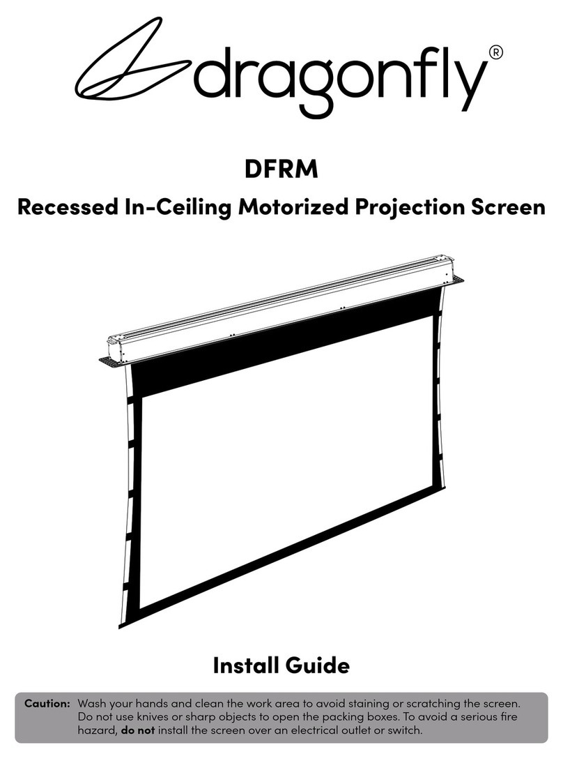
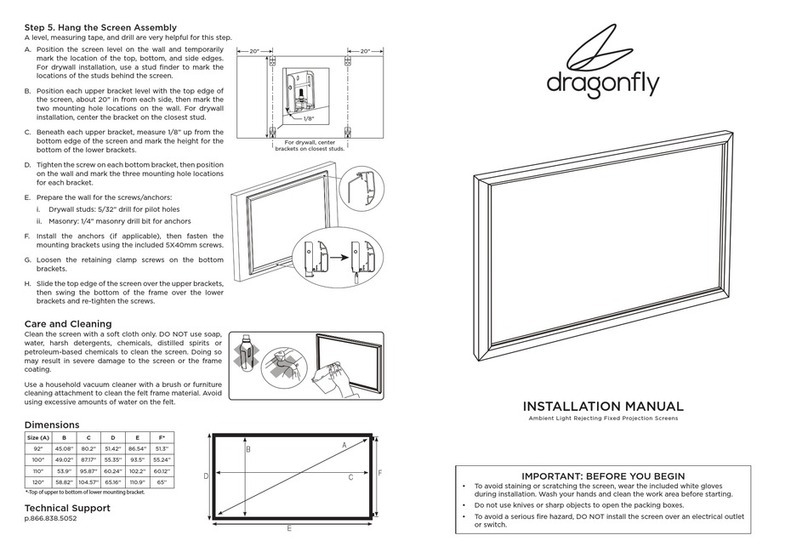
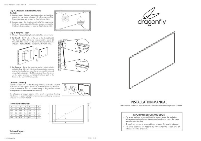
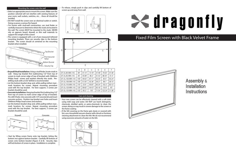
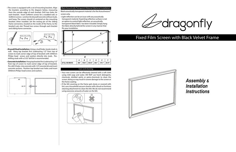
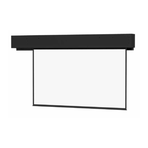
Dragonfly DFRM-TAB-100-MW User manual

INSTALLATION MANUAL
Recessed In-Ceiling Motorized Projection Screen

DFRM Installation Manual
Pg. 2
© 2016 Dragonfly
Important Safety Precautions and Warnings
Warning: To reduce the risk of fire or electric shock, do not expose this apparatus to rain or moisture.
1. Read and understand all instructions before using.
2. Do not use this apparatus near water.
3. Clean the screen housing only with a dry cloth.
4. Do not block any ventilation openings. Install according to manufacturer’s instructions.
5. Do not install near any heat sources such as radiators, heat registers, stoves or other
apparatus (including amplifiers) that produce heat.
6. Care must be taken as burns can occur from touching hot parts.
7. Do not operate appliance with a damaged cord or if the appliance has been dropped or
damaged - until it has been examined by a qualified
8. Position the cord so that it will not be tripped over, pulled, or contact hot surfaces.
9. If an extension cord is necessary, a cord with a current rating at least equal to that of the
appliance should be used. Cords rated for less amperage than the appliance may overheat.
10. To reduce the risk of electric shock, do not disassemble this appliance, but take it to a
qualified serviceman when service or repair work is required. Incorrect reassembly can cause
electric shock when the appliance is used subsequently.
11. The use of an accessory attachment not recommended by the manufacturer may cause a risk
of fire, electric shock, or injury to persons.
12. SAVE THESE INSTRUCTIONS.
CAUTION
CAUTION: TOREDUCE THE RIS K OF
ELECTRICAL SHOCK.
DONOT REMOVE COVER. NOUSER
SERVICEABLE PARTS INSIDE.
REFER SERVICING TOQUALIFIED
SERVICE PERSONNEL.
The lightning flash with arrowhead symbol,
within an equilateral triangle, is intended to
alert the user to the presence of uninsulated
dangerous voltage within the product’s
enclosure that may be of sucient magnitude
to constitute a risk of electric shock to
persons.
The exclamation point within an equilateral
triangle is intended to alert the user to
the presence of important operating and
maintenance (servicing) instructions in the
literature accompanying the appliance.
Before unpacking the projection screen, read the entire manual to become
familiar with the steps involved for installation and operation. Dragonfly is not
responsible for any damage or injury that occurs from incorrect installation or
operation.
DFRM Installation Manual
Pg. 3
1. Introduction
Thank you for purchasing a Dragonfly™ Motorized Projection Screen. Designed to be easy to
operate, reliable, and hidden away when not in use, this screen is guaranteed to provide years of
maintenance-free operation and enjoyment.
These screens feature several convenient mounting methods, can be controlled manually or
automatically by a control system or projector, and are fully adjustable. The screen material includes
a black, light-proof backing and optional adjustable tension tabs along each side to keep the
screen perfectly flat during use.
2. Package Contents
1x Projection
Screen
DC 12V Trigger
Cable 33’ (1)
RJ12 Control
Cable 10’ (1)
1x RF Remote
Ceiling Brackets
(2)
Housing Z Brack-
ets (2)
Mounting Bracket
Hardware (8 each)
M10 Nuts for
Threaded Rod (16)
Housing Door
Panel (1)
End Caps (2)
Mounting Anchors
(8)
M6 Concrete/
Wood
Ceiling Bolts (8)
IR Receiver
1 Meter M10
Threaded Rod (4)
Housing Flat
Brackets (2)
M10 Washers for
Threaded Rod (16)
Not pictured: Electrical junction box and power cable (attached to housing)

DFRM Installation Manual
Pg. 4
© 2016 Dragonfly
3. Installation
Important! Before installation, ensure that the ceiling structure is capable of
supporting the weight of the screen. Screen weights are listed in section, "7.
Assembled Weights" on page 13.
Step 1. Determine the Mounting Method
Z Brackets Flat Brackets
•Z Brackets – Used for all installations with new or existing permanent ceilings and when there
is no access above the screen housing such as an attic or a crawl space.
•Flat Brackets – Used for installations with new ceiling and access above the screen at all
times, such as a commercial tile ceiling, an attic, or a crawl space.
Step 2. Prepare the Ceiling Opening
Screen Housing Cutout
Use the chart to determine the opening size for the housing, then cut the ceiling surface.
Type-Size Length (A) Width (B)
A
B
C
TAB-100" 112.53" 7.25"
TAB-110" 121.19" 7.25"
TAB-120" 130.05" 7.25"
TAB-130" 138.79" 7.25"
NTT-100" 103.28" 7.25"
NTT-110" 111.90" 7.25"
NTT-120" 120.50" 7.25"
NTT-130" 129.30" 7.25"
Height Clearance (C)
Dimensions measured from bottom of ceiling surface to top of screen housing including height of
mounting bracket and hardware.
Z Bracket Down/Flat Bracket Z Bracket Up
7.0" 7.5"

DFRM Installation Manual
Pg. 5
Step 3. Install the Mounting Brackets
The mounting brackets are secured using hardware that slots into the rails on top of the housing.
Slide the bolts into the rail, position the brackets over the bolts, and tighten the nuts onto the bolts.
Z Bracket Installation
Point the brackets DOWN for threaded rod/suspended mounting or UP for direct ceiling mounting.
If the brackets are installed facing UP, position the bend in the bracket flush with the edge of the
screen housing.
DOWN UP
Straight Bracket Installation
Install the brackets a minimum distance apart to prevent instability after hanging the screen
housing. The brackets may be positioned o-centered as needed to fit the ceiling structure.
Size Minimum Bracket
Separation
100" 73.20"
110" 78.97"
120" 84.88"
130" 90.71"

DFRM Installation Manual
Pg. 6
© 2016 Dragonfly
Step 4. Install the Suspension Brackets/Hardware
This step may be skipped if threaded rod is NOT being used to suspend the screen.
Important! The hardware used to mount the screen MUST be able to support
the full weight of the installed assembly. Screen weights are listed in section, "7.
Assembled Weights" on page 13.
Threaded Rod Suspension with Z Brackets
Use the chart to determine the mounting locations of the included ceiling brackets.
Type-Size Center-to-Center
Bracket Distance
1.88”
1.88”
TAB-100" 111.10"
TAB-110" 119.80"
TAB-120" 128.50"
TAB-130" 137.24"
NTT-100" 101.65"
NTT-110" 110.35"
NTT-120" 119.06"
NTT-130" 127.80"
Assemble the threaded rod hanging assembly, then fasten the brackets to the ceiling. Use the
included screws and anchors for wood or masonry mounting, or supply your own hardware rated
for other ceiling surfaces. Use 2 pieces of threaded rod per side.
Threaded Rod Suspension with Z Brackets
Ceiling suspension hardware is not included for the flat brackets.
9.3”

DFRM Installation Manual
Pg. 7
Step 5. Hang the Screen Housing
Hang the screen from the threaded rod one side at a time. Have assistants hold the screen in
position on the rods, then thread a washer and a nut onto the rod. Use the nuts at the bottom of
each rod to adjust the final height.
Wood Joist Hanging
Mark the ceiling for the fasteners using the chart below. Have assistants hold the screen in position,
then fasten the assembly to the ceiling. Use the included screws and anchors for wood or masonry
mounting, or supply your own hardware rated for other ceiling surfaces.
Type-Size Center-to-Center Distance
TAB-100" 111.10"
TAB-110" 119.80"
TAB-120" 128.50"
TAB-130" 137.24"
NTT-100" 101.65"
NTT-110" 110.35"
NTT-120" 119.06"
NTT-130" 127.80"

DFRM Installation Manual
Pg. 8
© 2016 Dragonfly
Step 6. Connect Power Wiring
Warning! To avoid serious injury or death, power o electricity to the branch power
circuit at the breaker before connecting the screen wiring. High voltage electricity
can damage the screen and cause permanent injury or death!
Important! The electrical wiring should be installed in accordance with local and
national electrical codes. Only a licensed electrician should complete the work. All
work should be approved by a licensed inspector.
1. Position and mount the attached power junction box. Do not kink the flexible conduit during
installation.
2. Open the junction box and connect the branch wiring circuit conductors using approved wire
nuts or connectors.
Color Purpose
Black To 120V AC Line
White Neutral
Green Ground
Power Requirement
120V AC/.97A.

DFRM Installation Manual
Pg. 9
Step 7. Connect Control Wiring
EXT Control Connection
3.5mm Mono for
remote 3-12V DC
trigger
External IR Receiver
1 2 3 45 6
1 2 3 4 5 6
(Gold pins facing up)
Pin 6 - Up
Pin 5 - Down
Pin 4 - Stop
Pin 3 - Common
Pin 2 - RS232 Data Receive (RXD)
Pin 1 - RS232 Data Transmit (TXD)
RF Remote
Use the included remote for control of the screen from any direction. Remote uses AAA batteries,
included. If your remote will not operate the screen after installation, it may need to be paired:
1. Find the RF PAIRING button inside the casing (far left side) and hold it down for 5 seconds, until the screen will
drops approximately 1”. Release the button.
2. Press and hold the RF PAIRING button for another 5 seconds.
3. After 5 seconds, also begin pressing the “UP” arrow on the remote. After an additional 5 seconds, the remote
should be paired and the screen will move.
IR Receiver
Connect the included IR receiver to the EXT IR port for IR control up to 26ft away and at a maximum
angle of 30°. Mount the receiver using the adhesive foam tape on the back. (Note: The included IR
receiver is proprietary to Dragonfly projection screens. Other IR receivers will not work.)
3-12V DC Trigger
Connect the included 33 foot trigger wire from the TRIG port on the screen to the control out port
on a compatible projector for automatic control based on the projector.
RS232 Serial Control
Use pins 1 and 2 on the EXT CTRL port for one-way control. See the DFM Motorized Screen Control
Protocol for driver and command information, available on the product page support tab.
To connect wiring, either cut the included 10 foot RJ12 control cable and splice to the correct wires
or terminate a cable using a 6P6C RJ11/12 connector.
Contact Closure/Relay Control
The Dragonfly motorized screen may also be controlled via contact closure or relay control.
Momentarily short the COMMON wire to the UP, DOWN, or STOP wire for the desired operation.
The screen will stop automatically once a limit is reached, or the STOP function may be used to
stop at any desired position.
To connect wiring, either cut the included 10 foot RJ12 control cable and splice to the correct wires
or terminate a cable using a 6P6C RJ11/12 connector.

DFRM Installation Manual
Pg. 10
© 2016 Dragonfly
Step 8. Adjust Screen Travel
Set the final height of the screen during use and the closed position of the screen when not in use.
Limits are set using the RF remote and the limit adjustment button on the motor assembly.
Accessing the Adjustment Button
Open the access panel on the bottom of the housing by pulling down away from the magnets and
sliding the panel away from the viewing area. The button is next to the edge of the screen material.
Open Limit Adjustments
1. Stand in reach of the screen adjustment button while
holding the RF remote.
2. With the screen in the closed position, press the Down
button on the RF remote.
3. Once the screen has traveled within 6 inches of the desired
limit, press the adjustment button on the motor to stop the
screen.
4. Press the button repeatedly to adjust the screen to the
desired limit.
5. Once the screen is in the desired position, press the Up
button on the RF remote. The setting is saved.
Closed Limit Adjustments
1. Stand in reach of the screen adjustment button while
holding the RF remote.
2. With the screen in the open position, press the Up button on
the RF remote.
3. Once the screen has traveled within 6 inches of the desired
limit, press the adjustment button on the motor to stop the
screen.
4. Press the button repeatedly to adjust the screen to the
desired limit.
5. Once the screen is in the desired position, press the Down
button on the RF remote. The setting is saved.
Note: Make sure to stop the screen using the adjustment button while there are several inches of
screen still exposed. Allowing the screen to travel too far into the housing will cause the bottom bar
to travel too far into the housing. If this occurs, remove the screen from the housing and unwrap
the bottom bar enough to hang from the opening again.
Screen travel
adjustment button

DFRM Installation Manual
Pg. 11
Step 9. Install the Trim Pieces
Install the end caps after the screen has been installed and leveled.
Step 10. Install the Fixed Panel
1. Begin with the screen completely retracted so that the hinged door is closed.
2. Ensure that the rubber stops on the magnetic brackets in the housing are resting against the
hinged door when closed for proper alignment of both doors.
3. Lower the screen enough for the hinged door to open and fall out of the way.
4. Install the fixed panel by hooking the edge into the front of the housing, then pushing the
panel up until the magnets attach it to the brackets.
5. After installing the panel, retract the screen to the closed position and adjust as needed for
flush appearance.

DFRM Installation Manual
Pg. 12
© 2016 Dragonfly
Step 11. Adjusting the Tab Tension Setting (TAB Models Only)
If the sides of the screen appear wavy or bent, the tab tension setting must be adjusted. Turn the
adjustment knob on each side until both sides are even and flat.
To tighten the tabs, turn the adjustment knob CLOCKWISE.
To loosen the tabs, turn the adjustment knob COUNTERCLOCKWISE.
4. Removing the Screen from the Housing (Optional)
The screen assembly can be removed from the housing to allow for painting the housing, for when
the housing must be installed in advance, or to service the motor assembly without damaging the
ceiling.
1. Begin with the screen lowered enough for the hinged panel to swing down and out of the
way.
2. Remove the housing access panel by pulling down and away from the magnets. Carefully pull
the panel away from the viewing area where the panel hooks into the housing.
3. Disconnect the wiring harness connector from the motor assembly (connector facing down,
attached to bracket).
4. Remove the retaining screw.
5. Move the assembly over and then down, taking care not to let the opposite end fall out of the
housing.
6. Store the assembly in a safe place to avoid damage.
Remove Push screen assembly up
and towards viewing area
5. Cleaning the Screen
Follow these guidelines to clean any marks or residue from the viewing surface:
• Do not clean the screen case with water.
• Use a dry cloth to clean dust and dirt from the housing and screen on regular occasions.
• To clean the screen material, use warm soapy water and a soft cotton cloth only. Never
use chemicals or abrasives to avoid damaging the surface of the material, which aect the
viewing quality of your screen.

DFRM Installation Manual
Pg. 13
6. Troubleshooting
Dragonfly screens are designed to function trouble-free for years of enjoyment. Most problems
occur due to simple issues. If you have trouble, check the installation while reviewing all instructions.
Some of the most common issues and solutions are also listed below.
Issue Solution
Screen does not react
to any form of control.
• If the screen is repeatedly reversed while in motion, it may stop
moving and reacting to any control method. This is a safety feature
that keeps the motor from overheating. If this occurs, stop testing
for about 5 minutes, then resume.
• Check the film screen power connection. Use a voltmeter to check
for power and that polarity is correct.
• Disconnect all control cables and use the manual control switch
on the bottom left side of the screen housing. If this works, check
the normal control method for operation for problems. Check the
wiring and control codes being used, or consult with the controller
manufacturer to confirm that all settings are correct. If this doesn’t
work, check power as indicated above.
Viewing surface is too
high or low. • See "Step 8. Adjust Screen Travel" on page 10.
RF control does not
work but other modes
do work.
• Change the batteries in the RF remote. (2x AAA alkaline)
•It may be necessary to follow the directions to pair the remote in Step 7 on
page 9.
7. Assembled Weights
Type-Size Weight (lbs.)
NTT-100" 86.5
NTT-110" 93.2
NTT-120" 106.2
NTT-130" 118.2
TAB-100" 95.4
TAB-110" 108.2
TAB-120" 119.0
TAB-130" 134.5

DFRM Installation Manual
Pg. 14
© 2016 Dragonfly
8. Dimensions
J
K
L
GH I
M
E
D
Fc
B
A
Dim.
Screen Type-Size (Inches)
TAB-100 TAB-110 TAB-120 TAB-130 NTT-100 NTT-110 NTT-120 NTT-130
A6.58" 6.58" 6.58" 6.58" 6.58" 6.58" 6.58" 6.58"
B6.77"6.77"6.77"6.77"6.77"6.77"6.77"6.77"
C8.50" 8.50" 8.50" 8.50" 8.50" 8.50" 8.50" 8.50"
D111.50" 120.12" 128.98" 137.80" 103.07" 111.77" 120.47" 129.21"
E109.80" 118.46" 127.32" 136.06" 100.98" 109.69" 118.39" 127.13"
F114.53" 123.19" 132.05" 140.79" 106.14" 114.84" 123.54" 132.28"
G15.75" 15.75" 15.75" 15.75" 39.37" 39.37" 11.81" 11.81"
H10.16" 10.16" 10.16" 10.16" 8.50" 8.50" 8.50" 8.50"
I8.19" 8.19" 8.19" 8.19" 6.54" 6.54" 6.54" 6.54"
J49.02" 53.93" 58.82" 63.74" 49.02" 53.94" 58.82" 63.74"
K87.17" 95.88" 104.57" 113.31" 87.17" 95.87" 104.57" 113.31"
L3.94" 3.94" 3.94" 3.94" 1.97" 1.97" 1.97" 1.97"
M102.52" 111.23" 119.92" 128.66" 93.86" 102.56" 111.26" 120.00"
*TAB model shown; dimension pattern is the same for both models.

DFRM Installation Manual
Pg. 15
9. Specifications
Models DFRM-TAB-XXX-MW
DFRM-TAB-XXX-HC
DFRM-TAB-XXX-UAW
DFRM-TAB-XXX-UW
DFRM-NTT-XXX-MW
DFRM-NTT-XXX-HC
DFRM-NTT-XXX-ALR
Screen Material PVC and fiberglass woven inner layer
Gain High Contrast (HC) = .8 Gain
Matte White (MW) = 1.0 Gain
Ultra White (UW) = 1.3 Gain
Ultra AcoustiWeave (UAW) = 1.0 Gain
Ambient Light Rejection (ALR) = .8 Gain
Frame Construction: Housing: Aluminum Alloy, white
Motor: 120V AC/.97A
Duty Cycle ON = 1 minute
OFF = 5 minutes
10. 2 Year Limited Warranty
Dragonfly Motorized and Tab-Tension Motorized Projection Screens have a 2-Year Limited Warranty.
This warranty includes parts and labor repairs on all components found to be defective in material
or workmanship under normal conditions of use. This warranty shall not apply to products which
have been abused, modified or disassembled. Products to be repaired under this warranty must be
returned to a designated service center with prior notification and an assigned return authorization
number (RA).
11. Contact Technical Support
Phone: (866) 838-5052

© 2016Dragonfly
170227-1006
This manual suits for next models
27
Table of contents
Other Dragonfly Projection Screen manuals

Dragonfly
Dragonfly Ultra White User manual

Dragonfly
Dragonfly DF-SL-92-ALR User manual

Dragonfly
Dragonfly 92-145 User manual

Dragonfly
Dragonfly DF-TB-XXX-ALR Series User manual

Dragonfly
Dragonfly Acoustiweave DF-SL-160-MW Programming manual

Dragonfly
Dragonfly DFM-TAB-84 User manual

Dragonfly
Dragonfly Thinline 92" User manual

Dragonfly
Dragonfly DF-SL-84-MW/HC User manual

Dragonfly
Dragonfly DFRM User manual

Dragonfly
Dragonfly DFM-NTT User manual