10 11
SACS DE RÉCUPÉRATION JETABLES
POUR ASPIRATEURS CENTRAUX
DISPOSABLE DUST BAGS
FOR CENTRAL VACUUMS
AVERTISSEMENT
Nepas aspirerde matières considérées
toxiques,cancérigènesou dangereuses.
Gardezhorsde portée des enfants.
WARNING
Donot vacuummaterials considered
astoxic,carcinogenic or hazardous.
Keepawayfrom children’s reach.
SAC14
Drainvac :
PRO2*
GÉNÉRATION 2*
SUMMUM*
2000 & 3000
* Différents modèles d’une même gamme peuvent être configurés avec une sortie de
poussière différente. Veuillez préalablement vérifier la configuration de votre modèle.
(Se référer au verso).
* Different models of the same product line can have different dust outlet configurations.
Please check your model’s configuration beforehand (refer to back).
Purvac :
STANDARD*
DE LUXE*
EXTRA*
POUR LES GAMMES :
FORPRODUCT LINES:
41 L (9 gal.)
POUR LES CUVES DE :
FORCANISTERS OF:
Les 2 plis offrent une filtration
doublement efficace
The2 plies offer an extraefficient filtration
Pour matière sèche seulement
Fordry materialsonly
Pour usage domestique
Forhouseholduse
Facile à installer
Easyto install
2
PAPIER
PAPER
SACS DE RÉCUPÉRATION JETABLES
POUR ASPIRATEURS CENTRAUX
DISPOSABLE DUST BAGS
FOR CENTRAL VACUUMS
AVERTISSEMENT
Nepas aspirerde matières considérées
toxiques,cancérigènesou dangereuses.
Gardezhorsde portée des enfants.
WARNING
Donot vacuummaterials considered
astoxic,carcinogenic or hazardous.
Keepawayfrom children’s reach.
2
TISSU
CLOTH
SAC20
Drainvac :
PRO2*
GÉNÉRATION 2*
SUMMUM*
2000 & 3000
* Différents modèles d’une même gamme peuvent être configurés avec une sortie de
poussière différente. Veuillez préalablement vérifier la configuration de votre modèle.
(Se référer au verso).
* Different models of the same product line can have different dust outlet configurations.
Please check your model’s configuration beforehand (refer to back).
Purvac :
STANDARD*
DE LUXE*
EXTRA*
POUR LES GAMMES :
FORPRODUCT LINES:
41 L (9 gal.)
POUR LES CUVES DE :
FORCANISTERS OF:
Les 3 plis offrent une filtration
de haute efficacité
The3 plies offer a high efficient filtration
Pour matière sèche seulement
Fordry materialsonly
Pour usage domestique
Forhouseholduse
Facile à installer
Easyto install
SACS DE RÉCUPÉRATION JETABLES
POUR ASPIRATEURS CENTRAUX
DISPOSABLE DUST BAGS
FOR CENTRAL VACUUMS
AVERTISSEMENT
Nepas aspirerde matières considérées
toxiques,cancérigènesou dangereuses.
Gardezhorsde portée des enfants.
WARNING
Donot vacuummaterials considered
astoxic,carcinogenic or hazardous.
Keepawayfrom children’s reach.
2
TISSU
CLOTH
SAC32
Drainvac :
PRO2*
GÉNÉRATION 2*
SUMMUM*
* Différents modèles d’une même gamme peuvent être configurés avec une sortie de
poussière différente. Veuillez préalablement vérifier la configuration de votre modèle.
(Se référer au verso).
* Different models of the same product line can have different dust outlet configurations.
Please check your model’s configuration beforehand (refer to back).
Purvac :
STANDARD*
DE LUXE*
EXTRA*
POUR LES GAMMES :
FORPRODUCT LINES:
41 L (9 gal.)
POUR LES CUVES DE :
FORCANISTERS OF:
Les 3 plis offrent une filtration
de haute efficacité
The3 plies offer a high efficient filtration
Pour matière sèche seulement
Fordry materialsonly
Pour usage domestique
Forhouseholduse
Facile à installer
Easyto install
AVERTISSEMENT
Nepas aspirerde matières considérées
toxiques,cancérigènesou dangereuses.
Gardezhorsde portée des enfants.
WARNING
Donot vacuummaterials considered
astoxic,carcinogenic or hazardous.
Keepawayfrom children’s reach.
SACS DE RÉCUPÉRATIONJETABLES
POUR ASPIRATEURS CENTRAUX
DISPOSABLE DUST BAGS
FOR CENTRAL VACUUMS
2
TISSU
CLOTH
SAC31
Drainvac :
PRO1*
S1000*
Purvac :
STANDARD*
DE LUXE*
POUR LES GAMMES :
FORPRODUCT LINES:
17 L (3.75 gal.)
POUR LES CUVES DE :
FORCANISTERS OF:
Les 3 plis offrent une filtration
de haute efficacité
The3plies offer a high efficient filtration
Pour matière sèche seulement
Fordrymaterials only
Pour usage domestique
Forhouseholduse
Facile à installer
Easytoinstall
* Différents modèles d’une même gamme peuvent être configurés avec une sortie de
poussière différente. Veuillez préalablement vérifier la configuration de votre modèle.
(Se référer au verso).
* Different models of the same product line can have different dust outlet configurations.
Please check your model’s configuration beforehand (refer to back).
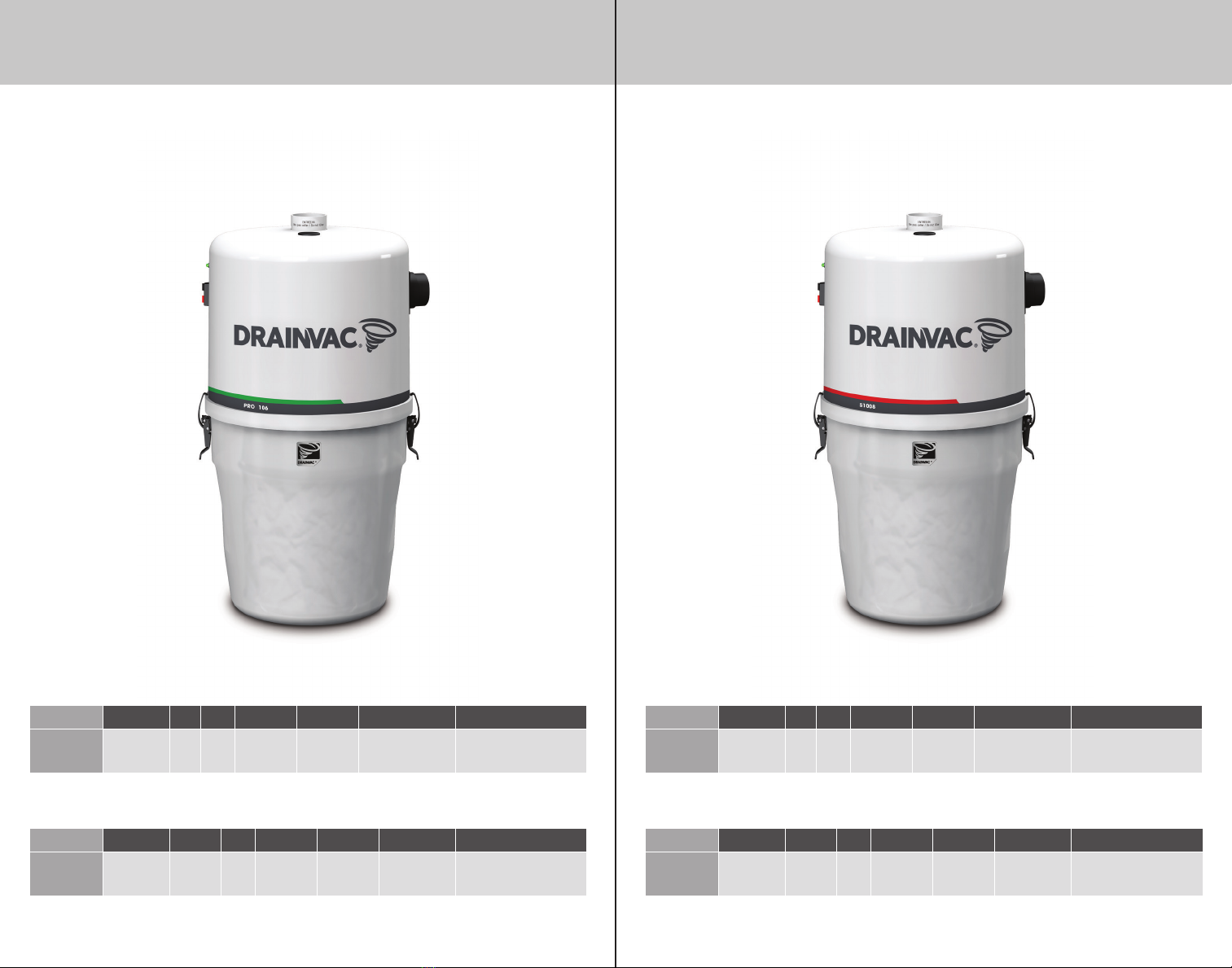
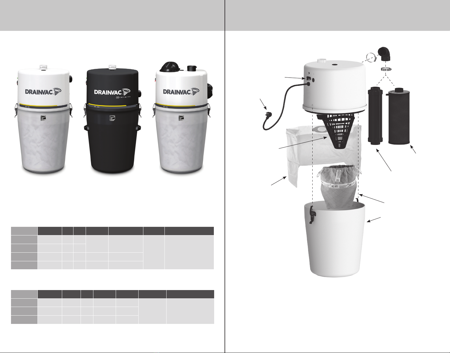
UNIT DESCRIPTION
ILLUSTRATED CONFIGURATION
OF A DUAL-MOTOR UNIT
G2-007i-M, G2E-007i-M, G2-2X3-M, G2-2X5-M, G2E-2X5-M
*Do not insert your hand in the metal cage while the unit is running.
Bucket
Power cord
Metal cage*
24V plug
Audioprotek
muffler
Audioprotek
muffler
Dust bag
Exhaust muffler
Filter
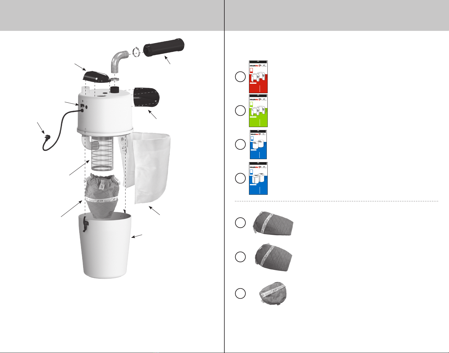
SAC14
Disposable 2-ply paper dust bags, 9 gal. (41L)
G2-007i-M, G2E-007i-M, G2-2X3-M, G2-2X5-M, G2E-2X5-M
SAC20
Disposable 3-ply cloth dust bags, 9 gal. (41L)
G2-007i-M, G2E-007i-M, G2-2X3-M, G2-2X5-M, G2E-2X5-M
SAC31
Disposable 3-ply cloth dust bags, 3,75 gal. (17L)
PRO106, PROE107, S1008, SE1007
FILT07DVI
Metal cage filter with a capacity of 9 gal. (41 L)
G2-007i-M, G2E-007i-M, G2-2X3-M, G2-2X5-M, G2E-2X5-M
FILT33DVI
Plastic cage filter with a capacity of 9 gal. (41 L)
G2-008, G2E-007
FILT30DVI
Plastic cage filter with a capacity of 3,75 gal. (17 L)
PRO106, PROE107, S1008, SE1007
DUST BAGS AND FILTERS
Please mark the dust bag and the filter which corresponds to your vacuum in order to
refer yourself when the time will come to change it.
Every model of the compact series is designed to operate with a dust bag and a cage
filter. Improper use will void the warranty.
SAC32
Disposable 3-ply cloth dust bags, 9 gal. (41L)
G2-008, G2E-007