Dramm HYDRA User manual

Owners Manual
Model HYDRA
Hydra Sprayer


Warranty ..................................................................................................................4
Warning....................................................................................................................5
Introduction..............................................................................................................6
Assembly and Preparation ......................................................................................6
Operation ..............................................................................................................6-7
Start-Up........................................................................................................6
Spray Operation ..........................................................................................7
Shut-Down ..................................................................................................7
Chemical Mixing Procedure ....................................................................................8
Maintenance & Cleaning ........................................................................................8
MSO40E Cart Parts and Assembly Diagram ..........................................................9
MSO40E Cart Parts List ..........................................................................................9
Plumbing, Hose Reel, and Gun Parts and Assembly Diagram ..............................10
Plumbing, Hose Reel, and Gun Parts List..............................................................11
Spray Gun Parts and Assembly Diagram ..............................................................12
Spray Gun Parts List ..............................................................................................13
Crank Case and Inlet Valve Parts and Assembly Diagram....................................14
Crank Case and Inlet Valve Parts List....................................................................15
Pressure Regulator Valve Parts and Assembly Diagram ......................................16
Pressure Regulator Valve Parts List ......................................................................17
Troubleshooting................................................................................................18-19
Notes ....................................................................................................................20
Hydra Sprayer Manual 3
Table of Contents
Printed in the USA 3.2003
HYDRA50-MAN1

120 Volt 60 HZ
11.4 AMPS
_________________________________________________________________
Serial Number
Hydra MultiSpray Hydraulic Sprayer
Model: HYDRA
Limited Warranty
Dramm Corporation warrants, to the extent of the purchase price, that the Hydra Sprayer, model MSO40, will
be free from defects in materials and workmanship to the original purchaser for a period of six months. Parts
subject to wear are not covered under this limited warranty. Defects or damages due to the misuse, non-observance
of safety standards, or non-observance of EPA chemical guidelines are not covered under this limited warranty.
Please read and follow the instructions and heed warnings stated in the operating manual and on the Hydra Sprayer,
model MSO40.
Dramm Corporation makes no other further warranty, expressed or implied, and all other or further warranties,
including any warranties of merchantability or fitness for a particular purpose are expressly excluded.
In no event shall the manufacturer(s) or Dramm Corporation be liable for loss of product, profit or any other
special, incidental or consequential damages including, but not limited to, plant damage, property, or persons.
Dramm Corporation makes no warranty, expressed or implied, in regard to the efficacy of any pesticide or
other chemical which may be applied using the Hydra Sprayer.
This warranty begins on the date of original purchase. This warranty is void if there is no proof of purchase or
warranty registration on file. Mail the warranty registration card to the Dramm Corporation and keep the bill of sale
or invoice. If warranty service is required, please include a written description of the equipment malfunction, a
return address and telephone number. The Hydra Sprayer, model HYDRA, must be thoroughly cleaned of all
chemical residue and sent prepaid to:
Hydra Sprayer Service
c/o Dramm Corporation
2000 North 18th Street
Manitowoc, WI 54220
920.684.0227
Hydra Sprayer Manual 4

• Apply all chemicals according to EPA
Guidelines.
• Store in a clean, dry location– away from
children and unauthorized personnel.
• Remove all hoses and drain the pump prior to
storage.
• Do not drag the hoses over sharp objects or
bend excessively.
• Repair or replace all damaged or broken
hoses before using the Hydra Multispray.
• Before servicing the unit, disconnect the
Hydra Multispray from the power source.
• Do not store mixed chemicals. Use all of the
chemical mixture immediately.
• Do not adjust the Pressure Regulator Va l v e
past its stop.
WARNING
Hydra MultiSpray
Model: HYDRA
• Use only 120 volt electrical outlets.
• Use only 3-pronged grounded extension
cords and receptacle boxes.
• Keep all electrical connections away from
liquids.
• Clean after every use with warm soapy water
and then rinse with clean water.
• Wear protective clothing; respirator, hood,
gloves and boots when mixing and spraying
chemicals.
• Do not spray into the wind. Avoid the drift
of solution sprays.
• Do not direct the spray or spray gun at
yourself or anyone else.
• Be certain all hoses and connections are
secure prior to using the Heavy Duty
Sprayer.
• Avoid dry operation, since the spray solution
acts as a pump lubrication.
• Relieve the pressure before removing the
hoses or spray gun.
Hydra Sprayer Manual 5

Your MS040 Hydra comes to you ready to spray. After removing the sprayer from the crate, check the tank for any
additional parts and accessories. Connect the spray gun to the hose using the quick disconnect. Your machine is
now ready for use.
The Dramm Hydra MultiSpray is a hydraulic sprayer that offers a variety of flow rates with a variety of
pressures to allow for maximum flexibility. The Hydra can apply all formulations of chemicals including
insecticides, fungicides, Insect growth regulators, plant growth regulators, and disinfectants. The Hydra can
output all formulations without damage or corrosion to the pump.
The Dramm Hydra includes a maneuverable 1.5 hp sealed electric motor and a close-coupled pump capable of 4
gpm and 550psi, 50 gallon tank, and cart featuring rear casters, a convex reel with a separate lock and variable
drag system, 150 feet of high pressure spray hose, and a variable pattern trigger spray gun.
START UP
1. Connect the sprayer to a 120 Volt, 60 HZ, 15 amp,
grounded circuit using the cord and plug provided.
Keep all electrical connections away from liquids.
2. Fill the sprayer to the desired level. Do Not operate
the sprayer empty for more than a few seconds. The
water acts as a coolant and lubricant for the pump and
damage may occur.
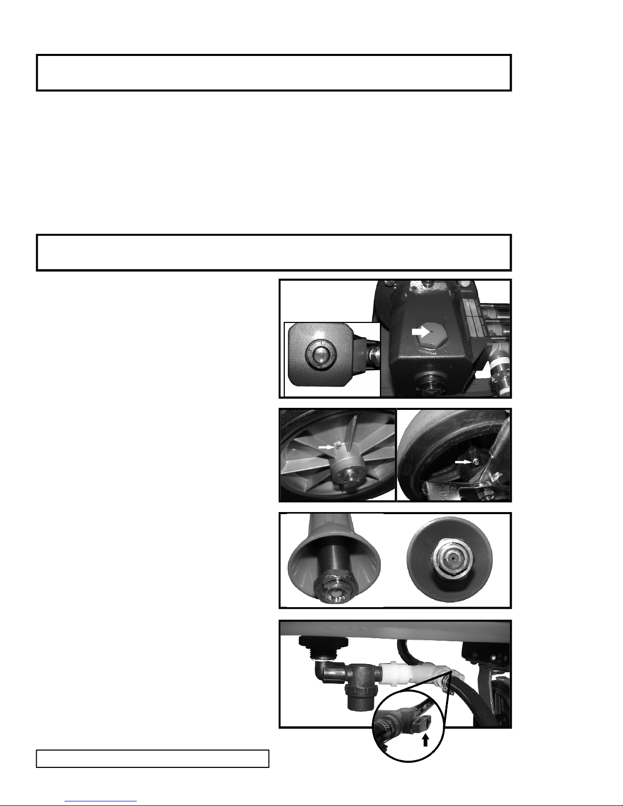
3. Start the sprayer with the pressure control knob in the
S T A R T position. (A). Do Notattempt to start the
sprayer under pressure as this will stall the motor and
cause an overload condition.
4. After starting the sprayer allow it to run with the
pressure control knob in the start position. This will
remove any air from the system, which can harm the
pump.
NOTE: If an extension cord is used it should be made
of 14 AWG wire or larger and should not exceed 100
Feet in length.
CAUTION: Keep all electrical connections away from
liquids. Use only three–pronged grounded receptacles
and extension cords.
A.
Hydra Sprayer Manual 6
Introduction
Assembly & Preparation
NOTE
• Always start and shutdown your sprayer with the
pressure regulator in the START (priming) position.
• Keep inlet filter clean.
• Always rinse the tank and flush the pump with clean
water after each use.

SPRAY OPERATION
1. After following the start up, to increase the spray
pressure, turn the pressure control knob to the desired
setting. (B) You may use any of these settings for
spraying, as the unit will operate properly at all
settings.
2. To begin spraying, pull the lever to the gun. A latch is
provided to hold the level open to reduce operator
fatigue. (C)
C A U T I O N:Do not direct the spray at yourself or
others, as injury may occur. On higher pressure
settings, the spray stream may cut or inject spray
under your skin. Always wear proper personal
protective gear when spraying.
3. Spray Pattern: Adjustment of the spray pattern is
made using the lever on the side of the gun. The
pattern will adjust from a straight stream to a fine
cone mist. (D)
4. Hose Reel: The Hydra MultiSpray comes standard
with a variable drag lockable hose reel. The reel may
be locked in position to prevent the hose from
unwinding further than wanted. (E) The variable
drag on the reel places variable tension on the reel to
prevent freewheeling of the reel during unwinding.
The drag has a lever to activate it. A nut allows for
tension adjustment. (F)
B.
Hydra Sprayer 7
Operation
SHUT-DOWN
1. After spraying until the tank is empty, turn the unit
off.
2. Add clear water to the tank. Start the machine and
spray until empty flushing out the pump hose and
gun.
3. Clean any residue from the unit.
4. Return the regulator to the START position.
5. Store the unit in a clean dry place.
6. Do Not allow the unit to freeze as any water left in
the unit will expand and damage the machine.
C.
E.
F.
D.

Hydra Sprayer Manual 8
Maintenance & Cleaning
1. Periodically check the pump oil level (G) If it is
below the indication add oil though the filler (H).
Use only Shell “Tellus #32” hydraulic oil or
equivalent.
2. Periodically lubricate the grease fittings on the
wheels (I &J) with a good grade of bearing grease to
extend the wheel bearing life.
3. Replace the spray gun tip every season. As the hole
in the tip gets larger the spray pressure drops and
degrades the quality of the spray. (K)
4. Thoroughly clean the in-line filter, tank and
machine on a weekly basis. (L)
5. To drain tank, rotate the drain valve (M) 180° until
the arrow on the valve handle indicates the direction
of flow is out the drain hose. *After draining, turn
the valve back to the Spray position. This
ensures that upon refilling the tank- the chemical
will not drain out of the unit.
I. J.
H.
L.
G.
K.
M.
Chemical Mixing Procedure
1. Fill the sprayer tank at least 3/4 full with water ONLY.
2. Dilute (mixing to dissolve) chemicals with water in a 5 gallon bucket. Never put concentrated chemical
formulations directly into the tank without diluting with water.
3. Start sprayer with pressure regulator in S T A R T (priming) position to beginagitation process prior to adding
chemical to sprayer tank.
4. Pour chemical and water mixture (slurry) into the sprayer tank, filled 3/4 full of water, after agitation has begun.
5. Fill remainder of sprayer tank with water.

MSO40E Cart Assembly
1 30CS820RSWB30 Hood Cap 2
2 D10924 Reel Mount Bracket 1
3 D11150 Reel Mount 1
4 D11191 Cart Frame 1
5 D11194 Handle Assembly 1
6 SN1230 12 X 3 Wheel 2
7 SP0045-AS 40 Gallon Tank 1
ITEM # PART # DESCRIPTION QUANTITY
Hydra Sprayer Manual 9

Hydra Sprayer Manual 10
MSO40E Plumbing, Hose Reel, and Spray Gun

Plumbing, Hose Reel, and Spray Gun Parts List Model MSO40
Hydra Sprayer Manual 11
1 127-B-04 1/4” Male Run Tee 1
2 1407-005 Elbow 1/2 MNP5 X 1/2 BARB 3
3 14297-1 Filter Housing 1
4 174121913-12’ Beldon Cord Set 1
5 56B17F540 1.5 HP Motor 1
6 24SA 08X04 Reducing Nipple 1
7 25A-06X04 1/4” Elbow 1
8 25A-06X04 3/8 X 1/4 Elbow 1
9 2T05R0812 1/2 ID Hose 2
10 42047 3/4 X 1/2 Coupling 1
11 42060 Bushing 1/2MPT X 1/4 FPT 1
12 42070 1/2 Elbow 1
13 4413-B Hose Reel 1
14 46971 Nipple 1/2 Brass Close 2
15 48335K142 1/2 X 3/8 Reducing Nipple 1
16 48335K162 Reducing Nipple 1
17 48335K205 Bushing 1
18 5372K124 Reducing Nipple 2
19 629-6F6F6F-B 2 Way PFC Drain Valve 1
20 7211 Gauge - 0-1000 PSI 1
21 8278005 Spray Tip 1
22 8284002 Geo 400 Spray Gun 1
23 896-WM 1/4 M to M Fitting 1
24 FD45--1004-0404 MQD Quick Disconnect Male 1
25 FD45--1005-0404 FQD Female Quick Disconnect 1
26 Hose Assy 150’ Hose 1
27 M412-005 1/2 Street Elbow 1
28 MSD 40 MSD 40 Pump 1
29 MSO 40 Hose Hose 1
30 Regal 801 Gasket 1
31 RSP 106 REMKKEY 1/2” ELECTRICAL CONNECTOR 1
32 TEE Tee 1
33 Unloading Valve Unloading Valve 1
ITEM # PART # DESCRIPTION QUANTITY

Hydra Sprayer Manual 12
MSO40E Spray Gun

Hydra Sprayer Manual 13
PART# DESCRIPTION QUANTITY
23.1003.16 Trigger Spring 1
23.1304.29 Push Pin 1
23.1310.8 Plug 1
23.1603.36 Flow Regulator Body 1
23.602.34 O-Ring 2
23.602.36 O-Ring 1
23.602.37 O-Ring 1
26.1304.33 Directional Switch 1
26.1506.14 Spacer 1
26.1617.10 Complete Flow Tube Assembly 1
26.1701.10 Nozzle 1
26.1703.55 Narrow Pattern Tube 1
26.1703.69 Flow Tube 1
26.1707.2 Spray Shield 1
26.1902.20 Screw 1
26.305.3 Spray Pattern Control Body 1
26.605.50 Wing Nut 1
26.801.5 Spacer 1
26.902.6 Spray Pattern Control Valve 1
29.1003.24 Spring 1
29.1101.1 Nipple 1
29.1607.3 Trigger Pin 1
29.1702.26 Plug 1
29.1903.9 Complete Trigger Valve Assembly 1
29.208.131 Valve Body 1
29.507.10 Trigger Locking Clip 1
29.801.40 Stopper 1
29.902.8 Trigger 1
71.602.6 O-Ring 1
Spray Gun Parts List Model MSO40

Hydra Sprayer Manual 14
MSO40E Crank Case and Inlet Valve

11/26/02 #
Hydra Sprayer Manual 15
1-1 354040 MSD40(5/8IN) 1
1-2 546000 Label 1
1-3 546041 Crankcase 1
1-4 044839 Oil Filler Cap 1
1-5 014179 O-Ring 1
1-6 044842 Plug 1
1-7 014179 O-Ring 1
1-8 546772 Crankshaft 1
1-9 044857 Bearing Case 1
1-10 014488 Bearing 1
1-11 044859 OIl Seal 1
1-12 014044 O-Ring 1
1-13 089551 Bolt 3
1-14 150810 Seal Washer 3
1-15 015710 Bearing 1
1-16 012385 Snap Ring 1
1-17 092241 Oil Gauge Assembly 1
1-18 044428 Packing 1
1-19 541811 Cylinder Pipe 3
1-20 045876 Connecting Rod 3
1-21 016948 Piston Pin 3
1-22 541809 Piston Pin 3
1-23 020017 Washer 3
1-24 025461 Oil Seal 3
1-25 044869 Seal Retail 3
1-26 011402 Oil Wick 3
1-27 545944 Inlet Manifold 1
1-28 540670 U-Packing13 3
1-29 639503 Inlet Valve Assembly 3
1-30 014122 Inlet Valve Seat 3
1-31 116121 Piston Packing 3
1-32 027348 Spacer 3
1-33 119917 Retainer, Piston 3
1-34 015849 Spring Washer 3
1-35 046365 Nylon Nut 3
1-36 023172 O-Ring 6
1-37 546860 Pipe Receiver 6
1-38 015862 O-Ring 6
1-39 544499 Discharge Manifold 1
1-40 044881 Valve Seat 3
1-41 044565 Retainer 3
1-42 043723 Discharge Valve 3
1-43 541062 Spring 3
1-44 544090 Cap Screw 6
ITEM # PART# DESCRIPTION QUANTITY
Crank Case and Inlet Valve Parts List

Hydra Sprayer Manual 16
MSO40E Pressure Regulator Valve

Pressure Regulator Valve Parts List
Hydra Sprayer Manual 17
2-1 546849 Pressure Regulator Valve 1
2-2 540936 Grip 1
2-3 088913 Cap Screw 1
2-4 081039 Nut 1
2-5 087483 Screw 2
2-6 088912 Cap Screw 1
2-7 106495 Guide 1
2-8 106499 Washer 1
2-9 541769 Retainer 1
2-10 109298 Spring 1
2-11 546500 Body 1
2-12 107221 Spring 1
2-13 106498 Ball 1
2-14 543591 Piston Assembly 1
2-15 103306 Sleeve 1
2-16 019261 O-Ring 1
2-17 543507 Valve Seat 1
2-18 019261 O-Ring 1
2-19 542258 Tee 1
2-20 541796 Cock Assembly 1
ITEM # PART# DESCRIPTION QUANTITY

CAUSE
• Suction strainer is blocked with
debris
• Suction hose is damaged or
crooked
• Suction hose connector gasket is
bad
• Connection is bad
• Debris is stuck in inlet or
discharge valve
• Inlet or discharge valve is
assembled improperly
• Inlet or discharge valve is
damaged or worn
• Discharge valve spring is
damaged
• Piston packing is damaged
• O-ring is damaged
• Seal & packing are damaged
• Pressure regulator valve lever in is
RUN position
• Pressure regulator is stuck
• Insufficient liquid supplied to
intake
• Pressure regulator valve ball or
valve seat damaged
• Pressure regulator valve rod is bad
• Pressure regulator valve spring
bad
• Pressure regulator valve spring is
damaged or weak
REMEDY
• Clear and clean
• Repair or replace
• Repair or replace
• Connect properly
• Clean
• Assemble properly
• Repair or replace
• Replace
• Replace
• Replace
• Replace
• Return lever to START position
• Disassemble & clean
• Diagnose under (1)
• Replace
• Adjust or replace
• Repair or replace
• Replace
PROBLEM
• Suction is Low or Absent
–Up to Suction Port
–Suction & Pressure
Parts (Cylinder Part)
–Pressure Regulator
Part
• Pressure Will Not Increase
–Suction & Pressure
Part
–Pressure Regulator
Part
Troubleshooting
Hydra Sprayer Manual 18
This power sprayer troubleshooting section shows how to diagnose and resolve problems that may occur in the
course of normal operation. If you experience a problem, take the steps indicated for the applicable diagnosis.
When you can't determine the cause of a problem or if you have any difficulty, please feel free to contact your
nearest dealer or this company's sales office. Please have the following information ready: 1. Model designation 2.
Serial number 3. Description of problem (What happened? What were you doing when it happened? What were the
conditions when it happened?) For items marked with *, please request adjustment or repair from your nearest
dealer or from this company's sales office.
WARNING: Do not change the setting of the screw that is under the cap on the top of the pressure regulator knob.
This screw absolutely must not be changed, since that will raise the pressure above rated specifications, damage the
machine, and possibly cause injury.

CAUSE
• Nozzle is worn
• Nozzle sprays too much liquid
• Intake liquid amount is too small
• Sprayer hose is too long
• Sprayer hose it too narrow gauge
• Water is leaking at hose
connection parts
• Pressure regulator valve works
poorly
• Faults in intake or pressure
assemblies (stopped up, slack)
• Loose or worn key
• Conrod bolt or other bolt is loose
• Bearings are damage
• Pressure regulator valve is
assembled wrong
• Air is being drawn in
• O-rings are damaged
• Seal & packing are damaged
• Oil seal is damaged
• Clamping or assembly are
incorrect
REMEDY
• Replace
• Replace with suitable nozzle
• Diagnose under (1)
• Make it the proper length
• Make it the proper gauge
•Repair or replace
• Disassemble or adjust
• Clean
• Tighten or replace
• Tighten
• Replace
• Adjust
• Inspect
• Replace
• Replace
• Replace
• Disassemble or adjust
• Make sure pressure control knob is
in start position
• Check electrical connections to
unit
• Check condition of switch
• Check condition of cord
• Have all motor or electrical
service done by a qualified
electrician
PROBLEM
• Pressure Falls When Spray
Gun is Opened
–Nozzle
–Power Spray
–Hose
• Sprayer Hose Vibrates
• Noise
• Liquid or Oil Leak
• Motor Will Not Run
Troubleshooting
Hydra Sprayer Manual 19

Notes
Hydra Sprayer Manual 20
Table of contents
Other Dramm Paint Sprayer manuals

Dramm
Dramm CHEMDOSE CD-120 User manual

Dramm
Dramm pulsFOG Turbo Owner's manual

Dramm
Dramm Hydra SprayTrax User manual

Dramm
Dramm FM20 User manual

Dramm
Dramm BP-4 User manual

Dramm
Dramm MS071EH Owner's manual

Dramm
Dramm Autofog MLVH-10A User manual

Dramm
Dramm MS75E Owner's manual

Dramm
Dramm BP-4Li Owner's manual