Copyright © 2007 Draper Inc. Form Patriot_Inst07 Printed in U.S.A.
Wall Installation—
Brackets should fasten to studding or other structural supports within wall that
are capable of supporting weight of flag (310 lbs).
Suspended Installation—
Chains should be attached to solid beams or rafters above unit. If possible,
mounting brackets should be positioned so chains hang vertically. Turnbuckles
should be connected between chains and mounting brackets. After the unit
has been suspended, turnbuckles should be adjusted so that flag hangs level.
Recessed Installation—
Recess should be constructed to fit case with brackets (see “Case
Dimensions” on back page). Design recess so that entire bottom of case is
unobstructed to permit access to bottom panel, roller and flag for servicing if
required.
Hanging Patriot Case
General:
When locating flag and checking clearance for operation, remember flag is
not centered in case: see dimensional drawings on reverse. All installations
should observe these important criteria:
➀Unit should be positively and securely supported so that vibration or even
abusive pulling will not weaken installation.
➁Installer must insure that fasteners used are of adequate strength and
suitable for the mounting surface.
➂Entire bottom of case must be readily accessible after installation is com-
plete. Be sure the access door opens freely for adjustments and service.
➃Vertical (banner) flags have two mounting brackets; horizontal flags have
three. Brackets should be located along case to line up with supporting
beams or studding. Left hand bracket is normally secured just to right of
access door and right hand bracket about one foot from right end of case.
Please Note: Mount the case using the two end brackets first. If a center
bracket is provided, mount it last. The center bracket is designed to
prevent sagging of the case, and must be mounted so that it is level with
the others and does not force the screen case up.
➄Horizontal flags with three brackets must be mounted so that center bracket
is level with the others and does not force the case upward or downward.
➅Do not use the case to support adjacent sections of ceiling.
➆If trim pieces must be attached to case, do not permit screws to protrude
through ¾" wall of case. Do not attach trim with nails.
➇If case is painted, slot must be shielded to protect flag from paint splatters
and overspray.
➈Do not seal unit in ceiling until electrical connections have been made and
flag has been operated successfully. Flag must always be installed level so
that it will unroll correctly.
These instructions are meant as a guide only. They do not imply any
responsibility on the part of Draper, Inc. for improper installation or faulty
workmanship at the jobsite.
Installation/Operating Instructions
Patriot Motorized Flag by Draper
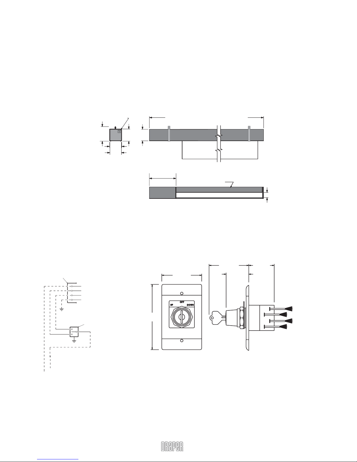
Electrical Connections
Unit operates on 110-120V, 60 hz. AC current.
Units are shipped with internal wiring complete, with all switches (fully boxed)
and a wiring diagram. Wire connecting unit to switch (or switches) and switch
to power supply should be supplied by installer or electrician. Wires should be
connected following the wiring diagram provided, and all wiring should comply
with local and national electrical codes.
All operating switches should be “Off” before power is connected.
Adjustments
Flag limit has been factory set and should not normally require further
adjustment. However, if you desire to change the “up” and “down” stopping
positions, proceed as follows:
CAUTION: Be sure all switches are in “off” position before adjusting limit
switches. Always be prepared to shut unit off manually when new adjustment
is being tested. Unit may be severely damaged if flag is allowed to run too far
up or too far down.
Adjusting “fully up” position — “Up” limit switch is located on right side of
limit switch assembly, immediately behind access door to case. Right hand,
hex head machine screw contacts limit switch button to shut unit off. Turning
this machine screw clockwise will allow flag to run farther up into case. Turning
it counterclockwise will cause flag to stop sooner, farther out of the case.
Adjusting “fully down” position — “Down” limit switch is located on left
side of limit switch assembly, immediately behind access door to case. Left
hand, hex head machine screw contacts limit switch button to shut unit off.
Turning this machine screw clockwise will allow flag to run farther down before
stopping. Turning it counterclockwise will cause flag to stop in a less extended
position. At no time should flag be unrolled far enough to expose any part
of the roller. Make all adjustments in small increments, and be sure nut on
machine screw is tight against steel limit switch support before closing access
door.
Caution
➀
Read instructions through completely before proceeding.
➁
Follow instructions carefully. Installation contrary to instructions invali-
dates warranty.
➂
Entire bottom of case should be unobstructed to permit access to
bottom panels for making electrical connections or servicing.
➃
Patriot should be installed level (using a carpenter's level).
➄
Nothing should be fastened to flag.
➅
Operating switch(es) packed separately in unit carton. Do not discard
with packing material.
➆
Unit operates on 110-120V AC, 60 hz. current.
NOTE: Unit has been thoroughly inspected and tested at factory and
found to be operating properly prior to shipment.
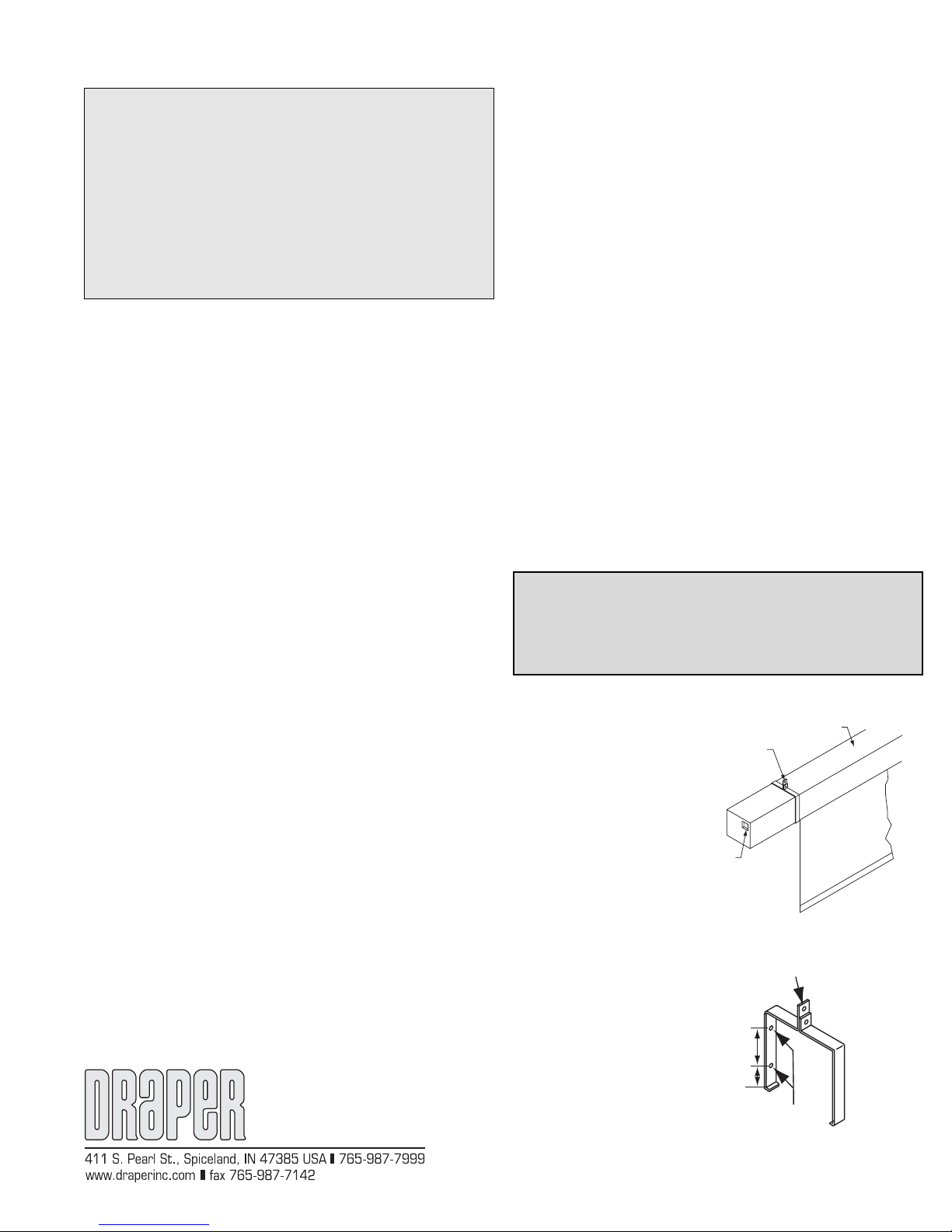
Universal Mounting Bracket
may be suspended from
above, or mounted to wall.
Each bracket consists of a front
and back piece bolted together.
2 supplied on vertical flags;
3 supplied on horizontal flags.
Case
Conduit connection
on left end of case.
Flag/Optional
Banner
For suspended mount.
For wall mount
6
3
/
8
"
1
3
/
8
"
Patriot Mounting Bracket
If you encounter any difficulties installing or servicing your Patriot motorized flag, call
your dealer or Draper, Inc., Spiceland, Indiana, (765) 987-7999, or fax (765) 987-7142.
Please Note: When installing a Patriot with a vertical OR
horizontal United States flag, please be sure the blue field
with stars is located in the upper left hand corner (as seen
from the front). See instructions on Position and Manner
of Display of U.S. Flag on page two prior to installation.”