Dresser 10C25 K Series User manual

© 2018 Natural Gas Solutions North America, LLC –All Rights Reserved.
Dresser™ Model 10C25 Series K Meter
Installation, Operation, and Maintenance Manual

Dresser Model 10C25 Series K Installation, Operation, and Maintenance Manual
© 2018 Natural Gas Solutions North America, LLC Page 2 of 74
Contents
1Introduction .....................................................................................................................4
2Overview..........................................................................................................................4
2.1 Operating Principle..................................................................................................................... 5
2.2 Performance Characteristics ...................................................................................................... 5
2.3 Features...................................................................................................................................... 5
3Receiving, Handling, and Storage......................................................................................6
3.1 At Time of Delivery ..................................................................................................................... 6
3.2 Storage........................................................................................................................................ 6
4Parts Identification...........................................................................................................7
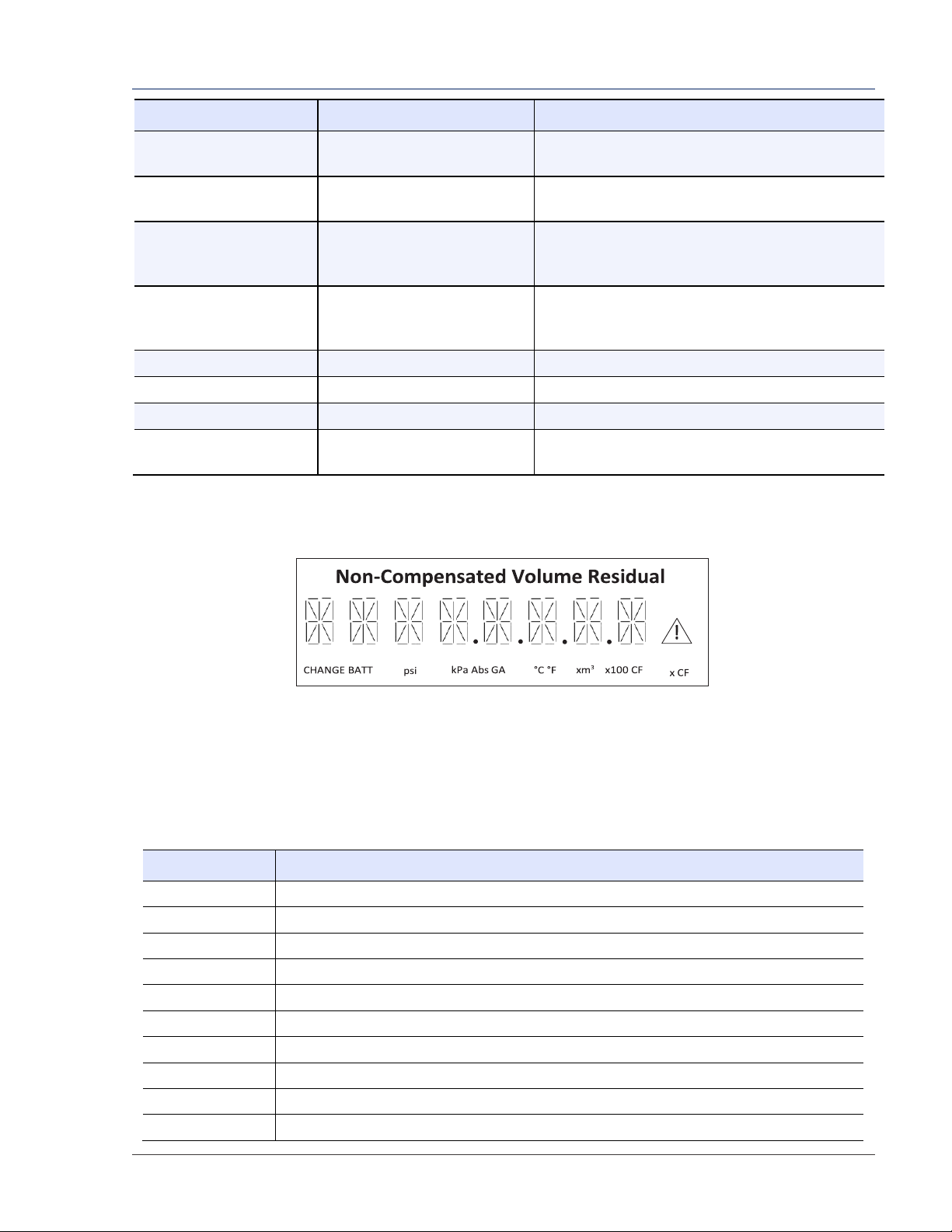
4.1 Meter Display ............................................................................................................................. 7
4.2 Flow Indicator........................................................................................................................... 10
5Problems with Installation or Operation .........................................................................10
6Meter Installation...........................................................................................................11
6.1 Preinstallation Considerations ................................................................................................. 11
6.2 Placing Meter in Line ................................................................................................................ 14
7Meter Startup ................................................................................................................15
8Downstream Leak Tests..................................................................................................16
8.1 Flow Indicator Method............................................................................................................. 17
8.2 Electronic Method –Magnetic Interface ................................................................................. 17
8.3 Electronic Method –MeterWare Interface.............................................................................. 18
9AMR Installation.............................................................................................................19
10 Pulse Output Connections ..............................................................................................24
10.1 Pulse Output Allocation Settings and Testing .......................................................................... 24
10.2 Wiring Instructions for Hazardous Locations ........................................................................... 25
11 Meter Operation ............................................................................................................28
11.1 MeterWare Software Information ........................................................................................... 28
11.2 Volume Measurement.............................................................................................................. 28
11.3 Temperature Measurement..................................................................................................... 29
11.4 Flow Rate Measurement .......................................................................................................... 30
11.5 Faults and Alarms ..................................................................................................................... 30

Dresser Model 10C25 Series K Installation, Operation, and Maintenance Manual
© 2018 Natural Gas Solutions North America, LLC Page 3 of 74
11.6 Logging Features....................................................................................................................... 33
12 Meter Maintenance........................................................................................................36
12.1 Meter Lubrication..................................................................................................................... 36
12.2 Meter Leveling.......................................................................................................................... 36
12.3 Meter and Digital Index Cleaning ............................................................................................. 36
12.4 Digital Index Replacement........................................................................................................ 36
12.5 Temperature Probe Insertion or Replacement ........................................................................ 39
12.6 Battery Maintenance................................................................................................................ 39
12.7 Removing the Meter from Service ........................................................................................... 45
13 Testing Procedure ..........................................................................................................46
13.1 Prover Test Mode Configuration.............................................................................................. 46
13.2 Proving with the Honeywell SNAP Prover ................................................................................ 49
13.3 Testing Modes .......................................................................................................................... 53
13.4 Proving with Dresser Model 5 Transfer Prover ........................................................................ 54
14 Differential Testing.........................................................................................................57
14.1 Establishing Baseline Curves .................................................................................................... 58
14.2 Pressure Differential Test Procedure ....................................................................................... 59
15 Upgrading Digital Index Firmware...................................................................................61
16 Troubleshooting .............................................................................................................64
17 Specifications .................................................................................................................65
18 Meter Capacity...............................................................................................................67
19 Warranty........................................................................................................................68

Dresser Model 10C25 Series K Installation, Operation, and Maintenance Manual
© 2018 Natural Gas Solutions North America, LLC Page 4 of 74
1Introduction
This manual provides information for installing, testing, operating, and maintaining the Dresser 10C25
Series K Digital Index non-compensated meter (10C25 DI) and the 10C25 Temperature Compensated
Digital Index meter (10C25 DI-T). Please read the entire manual for information about how to properly
and safely install, use, and maintain the meter and some of its accessories.
This manual provides recommendations when no established company procedure or practice is available.
The following additional resources are available:
•The Dresser MeterWare Software Manual, which contains detailed information about the meter’s
digital index software
•An Installation Supplement guide, which ships with the meter
Manuals are available by request or online at www.dresserngs.com.
2Overview
The Dresser 10C25 Series K (DI/DI-T) meter continues the Dresser legacy of superior long-term rotary
meter performance in a compact oil-free design.
The 10C25 meter body offers:
•A maximum flow rate of 1,000 acfh.
•An MAOP (maximum allowable operating pressure) of 25 psig.
•A functional and aesthetic design for situations in which a larger meter may draw unwanted
attention.
•Bi-directional flow capability that allows for more compact meter set designs.
•Direct replacement for the Dresser Series Z 5C15 and 8C15 ROOTS meters.
The 10C25 digital indexes offer:
•Innovative interconnection for AMR (automatic meter reading) devices pulse outputs including ease
of mounting and IP-68 watertight connections.
•A fast, two (2)-minute proving capability on Dresser Model 5 Transfer Provers and on common sonic
nozzle bench provers.
•Two (2) programmable pulse output signals.
•Dedicated alarm output.
•150 days of hourly logs stored in non-volatile memory.
•Programmable fixed-factor pressure correction.
The Dresser MeterWare software provides the user interface to the 10C25 digital indexes with an IrDA
(infrared) communication interface and is compatible with multiple Dresser metering products.

Dresser Model 10C25 Series K Installation, Operation, and Maintenance Manual
© 2018 Natural Gas Solutions North America, LLC Page 5 of 74
2.1 Operating Principle
The Dresser meter is designed to measure the volume of gases and gas mixtures with a high degree of
accuracy. The industry accepted rotary type positive displacement operating principle supports
permanent, non-adjustable accuracy by using precision machined two-lobe impellers encased within a
rigid measuring chamber. Measurement accuracy is not affected by changes in gas specific gravity,
pressure, or fluctuating flow.
Figure 1: Two (2) contra-rotating impellers of two-lobe or ‘figure 8’contour
As shown in Figure 1, two (2) contra-rotating impellers of two-lobe or ‘figure 8’design are encased within
a rigid measuring chamber that has inlet and outlet connections on opposite sides. Precision machined
timing gears keep the impellers in the correct relative position. Optimal operating clearances between the
impellers, cylinder, and headplates provide a continuous, non-contacting seal.
This design effectively isolates the gas at the meter inlet from the gas at the outlet. This enables a very
small pressure drop across the impellers to cause them to rotate.
2.2 Performance Characteristics
The 10C25 rotary meter has the following performance characteristics:
•Manufactured in accordance with the American National Standard specification ANSI/ASC-B109.3 for
rotary type gas displacement meters
•Not affected by low or varying line pressures
•Suitable for use at pressures ranging from a few inches of w. c. (water column) to the MAOP of 25 psig
•Mounts in the gas line like the Dresser™ Series Z 5C15 and 8C15 meters
2.3 Features
The 10C25 has the following features:
•Both horizontal (side) and vertical (top) mounting capability
•Oil-less with permanently lubricated bearings
•RPM (revolutions per minute) Flow Indicator to indicate flow
•Differential testing capability
•Fast prove feature available
•Compatible with common AMR/AMI devices that require pulse input
•Compensated and non-compensated versions available
•IP66 to IP68 rating (depending on pulse output configuration)
•Multiple connection types, including Sprague #3/#4, 30 LT, 45 LT, and 1-1/2 inch FNPT
For additional specifications, refer to Section 17.

Dresser Model 10C25 Series K Installation, Operation, and Maintenance Manual
© 2018 Natural Gas Solutions North America, LLC Page 6 of 74
3Receiving, Handling, and Storage
Follow the steps and recommendations in this section to ensure your meter and its accessories are ready
for installation and use.
3.1 At Time of Delivery
Perform the following steps when you receive your shipment:
1. Check the packing list to verify all items have been received.
2. Inspect each item for damage and, if necessary:
a. Record any visible damage or shortages on the delivery record.
b. File a claim with the carrier.
c. Immediately notify your Dresser meter supplier.
Note:
•Do not accept any shipment that appears damaged without immediately inspecting the
contents for damage.
•Check the meter for free rotation soon after arrival. Internal working parts might be
damaged without obvious external evidence. To check the meter, blow dry air lightly into
the meter inlet to verify the free rotation of the impellers.
3.2 Storage
If the product is not tested or installed soon after it is received, store it in a dry location in the original
shipping container for protection within the meter’s operating temperature range of -40°F to 140°F
(-40°C to 60°C).

Dresser Model 10C25 Series K Installation, Operation, and Maintenance Manual
© 2018 Natural Gas Solutions North America, LLC Page 7 of 74
4Parts Identification
Figure 2: Parts identification
4.1 Meter Display
View the meter information on its LCD (liquid-crystal display) screen.
4.1.1 Scrolling Through the Screens
To scroll through the different screens, swipe a magnet across the black dot to the right of the LCD screen
on the meter’s label, as shown in Figure 3.
Note: The screen will not change if the magnet is swiped on another area of the label.
Figure 3: Magnet used to change screens
Flow Indicator
(under sight glass)
LCD screen
Pulse output connector
IR window
IrDA cable holder slot
10C25 meter inlets
AMR meter bracket
mounting holes

Dresser Model 10C25 Series K Installation, Operation, and Maintenance Manual
© 2018 Natural Gas Solutions North America, LLC Page 8 of 74
The magnet can be purchased as part of the Communications Kit (refer to Figure 85) or individually by
part number, as shown in Table 1. Contact the Factory for pricing.
Table 1: Magnet Part Numbers
Part
Number (P/N)
Communications Kit
060542-000
Individual Magnet
060541-000
4.1.2 LCD Screen Displays
The home or default screen displays either Compensated Volume or Non-Compensated Volume,
depending on the meter version and customer configuration. After approximately thirty (30) seconds of
inactivity, the home screen displays.
Swipe the magnet vertically over the black dot on the meter’s label until the screen you want to view
displays. The screens always display in the order shown in Table 2. Depending on the meter configuration,
some screens might not display.
After the value’s name or parameter displays for three to five (3–5) seconds, the screen displays the
parameter’s value.
Note: Use the Dresser MeterWare software to configure parameters on the screens by
selecting or clearing the checkbox for the parameter to be displayed (refer to the Dresser
MeterWare Software Manual).
Table 2: Scrolling Sequence of LCD Screens
Displayed on Screen
Represents
Function
COMPENSATED VOLUME
Compensated Volume
Displays non-compensated volume that has been
corrected to standard conditions
NON-COMPENSATED
VOLUME
Non-Compensated Volume
Displays actual non-compensated volume
LINETEMP
Line Temperature
Displays live line temperature
FIXED P
Fixed Line Pressure
Displays the line pressure as entered by the user
FLOWRATE
Flow Rate
Displays uncorrected flow rate (average of latest
thirty (30) seconds of captured data)
MTR INFO
Meter Info
Displays meter size and type
LEAKTEST
Leak Test
Performs a functional test to determine low flow
leakage downstream of the meter
PROVE CV
Compensated Prove Mode
Allows for compensated volume accuracy testing
PROVE UV
Non-Compensated Prove Mode
Allows for non-compensated volume accuracy
testing
BATTVOLT
Battery Voltage
Displays battery voltage
REM LIFE
Remaining Battery Life
Calculates remaining battery life and displays it in
months
FIRM REV
Firmware Revision
Displays the current firmware revision
LCD TEST
LCD Test
Tests all display segments

Dresser Model 10C25 Series K Installation, Operation, and Maintenance Manual
© 2018 Natural Gas Solutions North America, LLC Page 9 of 74
Displayed on Screen
Represents
Function
BATT.CHNG
Change Battery
Saves data to memory and resets remaining battery
life to 240 months
COMPFCTR
Compensation Factor
Displays the factor applied to non-compensated
volume to calculate compensated volume
COMPENSATED RESIDUAL
Compensated Residual
Displays extended compensated volume data
beyond the value displayed on the compensated
volume screen
NON-COMPENSATED
RESIDUAL
Non-Compensated Residual
Displays extended non-compensated volume data
beyond the value displayed on the
non-compensated volume screen
BASE T
Base Temperature
Displays base temperature as entered by the user
BASE P
Base Pressure
Displays base pressure as entered by the user
PRESS FA
Fixed Pressure Factor
Displays the fixed pressure factor
NCVOLFLT
Non-Compensated volume
under fault
Displays non-compensated volume that has
accumulated since a fault occurred
4.1.3 Data Display Screen and Icons
Data displays in digital format, as shown in Figure 4.
Figure 4: Data display screen
Icons display depending on the function or parameter and how the meter is configured in the Dresser
MeterWare software. For icon descriptions, refer to Table 3.
For information about these data settings, refer to Section 11.
Table 3: Data Display Icons
Icon
Description
CHANGE BATT
Change Battery
psi
Pounds per Square Inch
kPa
Kilopascal
Abs
Absolute
GA
Gauge
°C
Temperature in Celsius
°F
Temperature in Fahrenheit
xm3
Cubic Meters
x100 CF
100 Cubic Feet
x CF
Cubic Feet

Dresser Model 10C25 Series K Installation, Operation, and Maintenance Manual
© 2018 Natural Gas Solutions North America, LLC Page 10 of 74
Icon
Description
Alarm/Fault has occurred; refer to Section 11.5
4.2 Flow Indicator
The white, reflective Flow Indicator located on the top of the meter (refer to Figure 5) serves two
purposes: It verifies the impeller rotation to indicate that gas is flowing, and it is also used as an optical
photo-sensor (scanner) when a proving device is testing the meter for accuracy.
Each revolution of the Flow Indicator indicates 0.007407 cf (0.0002098 m3) of non-compensated gas flow
through the meter.
Note: Keep the Flow Indicator covered by the rubber cap to help protect the viewing port
and keep it clean.
Figure 5: Flow Indicator location under cover in meter
5Problems with Installation or Operation
If you encounter any serious problems during installation or initial operation of the meter, immediately
notify your Dresser meter supplier.
Note: Do not attempt repairs or adjustments. Doing so might void all claims for warranty.
When reporting a suspected problem, complete the following steps:
1. Provide the following information to your Customer Service Representative:
•Purchase order number and/or sales order number
•Product model, serial number, and/or bill of material number
•Description of the problem
•Application information such as gas type, pressure, temperature, and flow characteristics
2. Pack all returns in the original shipping container or similar, if available, and use shipping material that
protects the product from damage during transit.
3. Contact your Dresser meter supplier to obtain an RMA (Return Materials Authorization) number.
The Dresser Product Services Department offers professional services for all Dresser Meters and
Instruments products. Authorization for return is required for all products shipped to the Factory for
repair, calibration, warranty, exchange, or credit. An RMA number is required to obtain authorization.

Dresser Model 10C25 Series K Installation, Operation, and Maintenance Manual
© 2018 Natural Gas Solutions North America, LLC Page 11 of 74
6Meter Installation
WARNING
Before installation, check the meter nameplate and verify that the MAOP (Maximum Allowable
Operating Pressure) and rated capacity for flow rate meet the installation requirements.
This section provides detailed information about proper installation of the 10C25 meter.
6.1 Preinstallation Considerations
Dresser meters are designed for continuously measuring and indicating accurate measurement of clean,
dry natural gas and other non-corrosive gases at constant or varying flow rates. The Dresser 10C25 meter
has excellent rangeability and is capable of accurately measuring small pilot loads. Contact your Dresser
meter supplier for a list of approved gases or additional performance details.
6.1.1 Installation Size Considerations
Verify that the selected installation location provides sufficient space for the meter (Figure 6 and Figure
7). Also allow additional space for an attached AMR device, if applicable.
Leave sufficient space around the meter to allow access to the LCD screen, AMR device, and cable access
for testing, as applicable.
Side Inlet Orientation–Side View
Side Inlet Orientation–Top View
Side Inlet Orientation–Front View
Figure 6: 10C25 Meter Size Specifications–Side Inlet Orientation (horizontal)

Dresser Model 10C25 Series K Installation, Operation, and Maintenance Manual
© 2018 Natural Gas Solutions North America, LLC Page 12 of 74
Top Inlet Orientation–Side View
Top Inlet Orientation–Top View
Top Inlet Orientation–Front View
Figure 7: 10C25 Meter Size Specifications–Top Inlet Orientation (vertical)
6.1.2 Environmental Considerations
The meter’s temperature operating range is from -40°F to 140°F (-40°C to 60°C). Verify that the location
where the meter is installed allows the temperature of the meter to remain within this range.
Ensure the meter can remain level within 1/16 inch per foot (5 mm/m) in any direction, side to side, and
front to back.

Dresser Model 10C25 Series K Installation, Operation, and Maintenance Manual
© 2018 Natural Gas Solutions North America, LLC Page 13 of 74
6.1.3 Piping Configurations
Figure 8: Top inlet (vertical)
Figure 9: Side inlet (horizontal)
The line mounted Dresser 10C25 meter can be installed in either a top inlet (vertical), a side inlet
(horizontal), or a bottom inlet (vertical) configuration.
A top inlet in a vertical pipe line with gas flow downward is the preferred or recommended installation.
The top inlet mounting allows gravity to pass dirt, pipe scale, or other debris through the meter.
A 60 mesh screen is recommended in the inlet connection.
CAUTION
•To avoid accumulation of condensate and foreign materials in the metering chamber, do not
install the meter lower than the discharge pipe run. Use a screen or strainer upstream of the
meter to remove liquids and foreign matter (pipe sealant, tape, weld slag, etc.) from the gas
stream. A 60 mesh screen is recommended.
•Do not install a lubricated gas valve directly before a meter; excess valve lubricant or other
foreign material can stop impeller rotation.
A meter bypass allows the meter to be tested by using a transfer prover while it is mounted in line.
If over-speed conditions can occur, a restricting flow orifice plate should be installed two to four (2–4)
pipe diameters downstream of the meter outlet. Contact Dresser Meters and Instruments for sizing,
pricing, and availability. The warranty does not cover over-speed conditions.

Dresser Model 10C25 Series K Installation, Operation, and Maintenance Manual
© 2018 Natural Gas Solutions North America, LLC Page 14 of 74
6.1.4 Safety Considerations
WARNING
To reduce the risk of severe injury or death, follow your company guidelines and industry accepted
practices. Other safety considerations are provided below:
•This equipment is designed to operate at temperatures between -40°F and 140°F (-40°C to 60°C).
Prior to going on-site for installation or maintenance, make sure proper safety equipment is worn
before handling the equipment and that you are properly dressed for the worksite environment
temperatures.
•Beware of sharp surfaces and potential pinch points while performing installation, maintenance,
and repair procedures. Use proper personal protective equipment and procedures.
•Follow proper safe site work practices to prevent fall and drop hazards if equipment is
installed/serviced/maintained at elevated heights.
•For installations in confined spaces, allow adequate room to safely handle product and
equipment without causing bodily strain. Also, verify proper ventilation is in place to maintain a
breathable atmosphere.
6.1.5 Installation Recommendations
Follow your company guidelines and industry accepted practices. In addition:
•Verify protective devices are in place to prevent personal injury and damage to vehicles and
equipment in areas of reduced visibility, such as next to parking lots or where the meter can become
covered in snow.
•Prevent debris and moisture from entering the meter to avoid possible damage and restriction of gas
flow. A strainer or filter upstream of the meter may be used to help remove contaminants such as
pipe sealant, tape, and weld slag from the gas stream.
6.2 Placing Meter in Line
Perform the following steps to install the meter in line:
DANGER
Venting gas into the atmosphere can create a hazardous environment. Follow your company
guidelines for venting gas into the atmosphere.
1. Before installing the meter, perform the following steps:
a. To prevent damage to the meter, purge the gas line to ensure the upstream piping is clean of
scale, dirt, liquids, and other debris. This purge is often done by venting the line to the
atmosphere.

Dresser Model 10C25 Series K Installation, Operation, and Maintenance Manual
© 2018 Natural Gas Solutions North America, LLC Page 15 of 74
b. If needed, change the orientation of the digital index for the configuration (vertical or
horizontal) in which the meter will be installed. For more information, refer to Section 12.4.
c. Verify the impellers turn freely and no objects or contaminants are in the measuring chamber.
To check the meter, blow dry air lightly into the meter inlet to verify the free rotation of the
impellers.
Depending on the meter’s condition, the meter might need to be flushed with an approved
solvent. Verify the measuring chamber is clean and dry and the impellers turn freely before
installing.
For information about cleaning the meter, refer to Section 12.3.
2. Connect the meter inlet to the gas supply side of the
line. Verify the gas will flow in the same direction as
the arrow on the meter body nameplate (for example,
the arrow is pointing downward for the top inlet or in
both directions for bi-directional flow).
Figure 10: Gas flow direction
3. Install the meter without piping strain to prevent binding.
4. Check the orientation of the meter with a level. The meter must be level within 1/16 inch per foot
(5mm/m) in any direction, side to side, front to back.
7Meter Startup
After proper installation and leveling of the meter, as described in Section 6, perform the following steps
to start up the meter:
1. Slowly open the meter inlet valve just enough to allow gas into the meter.
This gas flow allows the meter to pressurize. The Flow Indicator may start to rotate during this
process.
CAUTION
Do not exceed five (5) psig/second (35 kPa/second) maximum when pressurizing the meter.
Rapid pressurization can cause an over-speed condition, which may damage the meter.
Resulting damage is not covered by warranty.
2. Open the bypass and outlet (downstream of meter) gas valves.
3. Partially open the meter inlet gas valve until the meter starts operating at low speed. Throttling of the
bypass valve might be necessary to initiate gas flow through the meter.
4. Verify gas is flowing though the meter by watching for movement of the Flow Indicator to indicate
impeller rotation, and then proceed depending on the results:
•If movement is present, go to Step 5.
•If the Flow Indicator is not turning, verify gas is being delivered to the meter.
•If gas is flowing to the meter inlet and the Flow Indicator is not moving, go to Step 6.

Dresser Model 10C25 Series K Installation, Operation, and Maintenance Manual
© 2018 Natural Gas Solutions North America, LLC Page 16 of 74
5. Let the meter operate at low speed for several minutes. Listen closely for unusual scraping or
knocking sounds:
•If unusual sounds are present, go to Step 6.
•If the meter is operating normally, go to Step 7.
6. If unusual sounds are present or the Flow Indicator is not turning, place the meter in bypass. Slowly
depressurize and vent all pressure from the meter set before checking for piping misalignment, piping
strain, torsion, or other related problems. After the problem has been resolved, repeat the startup
procedure starting from Step 2.
WARNING
Do not adjust or work on the meter before slowly depressurizing and venting all pressure from
the meter set in accordance with company procedures or industry guidelines.
7. When the meter is operating smoothly, slowly open the inlet valve until a full line flow is passing
through the meter and the inlet valve is fully open.
8. Slowly close the bypass valve.
9. After the meter is pressurized, follow your company’s authorized procedures or common industry
practices to leak test the meter and all pipe connections. Soapy water, Snoop®, or gas analyzers are
commonly used for this procedure. The meter also incorporates a leak test feature, as described in
Section 8.
8Downstream Leak Tests
A leak test is commonly performed on a meter set after it is installed. The leak test feature on the 10C25
meter can detect a leak (or gas flow) at any point downstream of the meter cartridge.
Note: The meter will not detect leaks that are flowing below the start rate of the meter. Flow
above one (1) cfh is measured at +90% accuracy.
WARNING
Adhere to federal, state, company, and local codes and procedures, as applicable.
To perform a downstream leak test, use one of the following methods:
•Flow Indicator Method
•Electronic Method using the magnetic interface
•Electronic Method using the Dresser MeterWare software interface

Dresser Model 10C25 Series K Installation, Operation, and Maintenance Manual
© 2018 Natural Gas Solutions North America, LLC Page 17 of 74
8.1 Flow Indicator Method
The Flow Indicator is tied directly to the meter impellers and is extremely sensitive to flow.
To detect a leak, look at the white Flow Indicator on the meter and ensure it is not rotating. If it is
rotating, gas is flowing downstream of the meter.
For more information about the Flow Indicator, refer to Section 4.2.
8.2 Electronic Method –Magnetic Interface
If the LEAKTEST screen is not available, use the Dresser MeterWare software to enable this test feature
on the meter. For information about enabling this feature, refer to the Dresser MeterWare Software
Manual.
1. Use the magnet to scroll through the LCD
screens until LEAKTEST displays.
Figure 11: Leak Test (LEAKTEST) LCD screen
2. Hold the magnet on the black dot for five
(5) seconds until LKTST.RUN displays (Figure
12), and then remove the magnet. The leak test
process begins.
Figure 12: Leak Test Run (LKTST.RUN) LCD screen
The meter uses a preconfigured test sequence to run the leak test based on acceptable flow/volume
limits and time duration. Use the Dresser MeterWare software to change these parameters.
The default is a maximum flow rate of 0.5 cfh with a test duration of two (2) minutes.
After the leak test process completes, either a Leak
Test Pass Screen (Figure 13) or a Leak Test Fail
Screen (Figure 14) displays.
The meter holds this leak test result for 24 hours.
To access this test result within this time, view the
parameter value for LEAKTEST.
Figure 13: Leak Test Pass (LKT PASS) LCD screen
Figure 14: Leak Test Fail (LKT FAIL) LCD screen
3. If you want to repeat the leak test, first clear the screen by displaying the leak test result and
holding the magnet on the black dot next to the display screen. The screen returns to the Leak Test
run screen (LKTST.RUN) shown in Figure 12.

Dresser Model 10C25 Series K Installation, Operation, and Maintenance Manual
© 2018 Natural Gas Solutions North America, LLC Page 18 of 74
8.3 Electronic Method –MeterWare Interface
The Leak Test feature is also accessible in the Dresser MeterWare software through the Advanced screen,
as shown in Figure 15.
This method requires connecting to the meter by using the IR (infrared) communication cable. The IrDA
cable refers to the IR dongle connected to the USB extension cable. For more information, refer to
Appendix A.
With the Dresser MeterWare software, you can adjust the test parameters and run the leak test (refer to
Figure 16).
After the leak test process completes, PASS or FAIL displays on the screen (refer to Figure 17) and on the
meter (as described in Section 8.2).
For more information about running a leak test by using the Dresser MeterWare interface, refer to the
Dresser MeterWare Software Manual.
Figure 15: Advanced screen in Dresser MeterWare
Figure 16: Leak Test Parameters screen in
Dresser MeterWare
Figure 17: Leak test pass/fail indications in Dresser MeterWare

Dresser Model 10C25 Series K Installation, Operation, and Maintenance Manual
© 2018 Natural Gas Solutions North America, LLC Page 19 of 74
9AMR Installation
Perform the following steps to install an AMR (automatic meter reading) device, if applicable.
9.1.1 Preparing the AMR Cable
1. To allow for installation options, the provided AMR cable usually needs to be trimmed to the correct
length.
Determine the length of the cable needed. As shown in Figure 23, at least one (1) loop of extra cable
(slack) is needed.
If the AMR will be wall mounted, verify the cable is long enough to run from the AMR device location
to the meter without tension.
2. Connect the wires from the AMR cable to the
pulse output connector cable. Gel caps are
commonly used to connect the wires.
Follow the wiring instructions based on your
desired pulse output configuration (refer to
Section 10).
Contact your AMR provider to verify you have
the correct wiring configuration.
Figure 18: Example of gel caps
9.1.2 Mounting an AMR Device to the Meter
Tip: Remove the digital index from the meter for easier installation (refer to Section 12.4).
If the AMR device is to be mounted on the meter, perform the following steps:
1. Align the base AMR mounting bracket over the
holes on the top of the digital index.
2. Insert the screws into position and turn them until
they touch the cover.
3. Tighten the screws to a maximum torque of 18 inch
pounds.
Figure 19: Align and attach the base AMR
mounting bracket to the digital index

Dresser Model 10C25 Series K Installation, Operation, and Maintenance Manual
© 2018 Natural Gas Solutions North America, LLC Page 20 of 74
4. Push the AMR cable into the pulse output
connector until it locks into place.
Figure 20: Push the AMR cable into the pulse
output connector
Note:
•Trim the AMR cable to the correct length prior to connecting it (refer to Section 9.1.1).
•If needed, remove the cover over the pulse output connector.
5. Align the mounting holes on the AMR device with
the holes on the top AMR mounting bracket.
Note: The design of the top AMR
mounting bracket may differ from the one
shown in Figure 21.
Figure 21: Align AMR device with holes on
top AMR mounting bracket
This manual suits for next models
2
Table of contents
Other Dresser Measuring Instrument manuals