Dresser D Series Owner's manual

© 2019 Natural Gas Solutions North America, LLC – All Rights Reserved.
Dresser™Series D Meter
Models D800 and D1000
Installation Supplement

Dresser Series D Installation Supplement
© 2019 Natural Gas Solutions North America, LLC Page 2 of 24
Contents
1Introduction .....................................................................................................................3
2Receiving, Handling, and Storage......................................................................................3
2.1 At Time of Delivery ..................................................................................................................... 3
2.2 Storage........................................................................................................................................ 3
3Parts Identification...........................................................................................................4
3.1 Meter Display ............................................................................................................................. 4
3.2 RPM Wheel................................................................................................................................. 5
4Problems with Installation or Operation ...........................................................................5
5Meter Installation.............................................................................................................6
5.1 Preinstallation Considerations ................................................................................................... 6
5.2 Placing Meter in Line .................................................................................................................. 8
6Meter Startup ................................................................................................................11
7Downstream Leak Tests..................................................................................................12
7.1 RPM Wheel Method................................................................................................................. 12
7.2 Electronic Method – Magnetic Interface ................................................................................. 12
7.3 Electronic Method – MeterWare Interface.............................................................................. 13
8AMR Installation.............................................................................................................14
9Pulse Output Connections ..............................................................................................19
9.1 Pulse Output Allocation Settings and Testing .......................................................................... 20
9.2 Wiring Instructions for Hazardous Locations ........................................................................... 21

Dresser Series D Installation Supplement
© 2019 Natural Gas Solutions North America, LLC Page 3 of 24
1Introduction
This manual provides information to install and start using the Dresser D800/D1000 Series D meters.
Please read the entire manual and refer to the Dresser Series D Installation, Operation, and Maintenance
Manual for information about how to properly and safely install, use, and maintain these meters and
some of their accessories. The Dresser MeterWare software provides the user interface to the meter’s
digital indexes with an IrDA (infrared) communication interface.
This manual provides recommendations when no established company procedure or practice is available.
The following additional resources are available:
•The Dresser™ Series D Meter Installation, Operation, and Maintenance Manual, which contains
detailed information about installing, operating, and maintaining the D800 and D1000 Series D meters
•The Dresser MeterWare Software Manual, which contains detailed information about the meter’s
digital index software
Manuals are available by request or online at www.dresserngs.com.
2Receiving, Handling, and Storage
Follow the steps and recommendations in this section to ensure your meter and its accessories are ready
for installation and use.
2.1 At Time of Delivery
Perform the following steps when you receive your shipment:
Check the packing list to verify all items have been received.
Inspect each item for damage and, if necessary:
a. Record any visible damage or shortages on the delivery record.
b. File a claim with the carrier.
c. Immediately notify your Dresser meter supplier.
Note:
•Do not accept any shipment that appears damaged without immediately inspecting the
contents for damage.
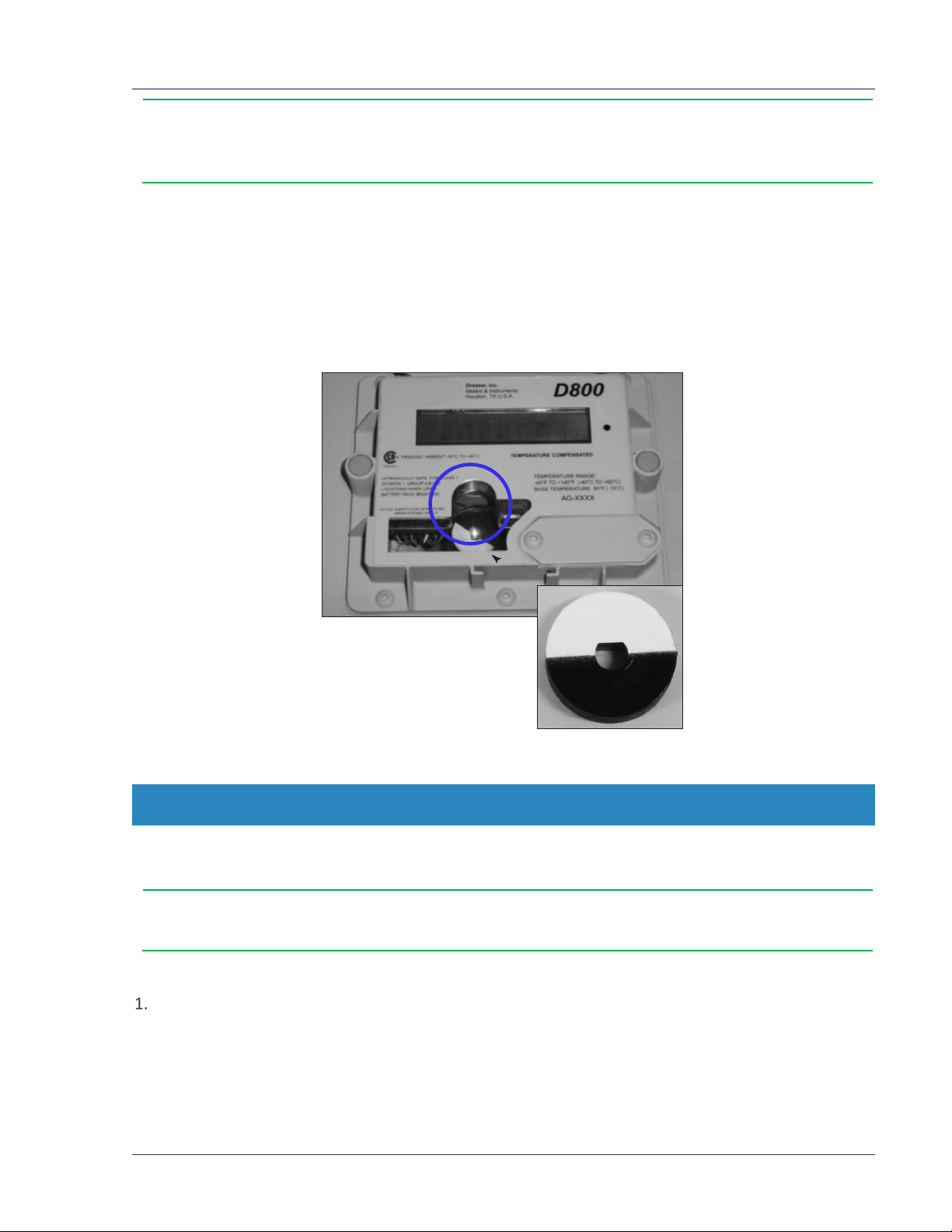
•Check the meter for free rotation soon after arrival. Internal working parts might be
damaged without obvious external evidence. To check the meter, blow dry air lightly into
the meter inlet to verify the free rotation of the impellers.
2.2 Storage
If the product is not tested or installed soon after it is received, store it in a dry location in the original
shipping container for protection within the meter’s operating temperature range of -40°F to 140°F
(-40°C to 60°C).

Dresser Series D Installation Supplement
© 2019 Natural Gas Solutions North America, LLC Page 4 of 24
3Parts Identification
3.1 Meter Display
View the meter information on its LCD (liquid-crystal display) screen.
3.1.1 Scrolling Through the Screens
To scroll through the different screens, swipe a magnet across the black dot to the right of the LCD screen
on the meter’s label, as shown in Figure 1 and Figure 2.
Note: The screen will not change if the magnet is swiped on another area of the label.
Figure 1: Label on D1000 meter
Figure 2: Swipe magnet across black dot to
change the screen
The magnet can be purchased as part of the Communications Kit or individually by part number, as shown
in Table 1. Contact the Factory for pricing.
Table 1: Magnet Part Numbers
Part Number (P/N)
Communications Kit 060542-000
Individual Magnet 060541-000
3.1.2 LCD Screen Displays
The home or default screen displays either Compensated Volume or Non-Compensated Volume,
depending on the meter configuration. After approximately thirty (30) seconds of inactivity, the home
screen displays.
Swipe the magnet vertically over the black dot on the meter’s label until the screen you want to view
displays. Depending on the meter configuration, some screens might not display.
After the value’s name or parameter displays for three to five (3–5) seconds, the screen displays the
parameter’s value.

Dresser Series D Installation Supplement
© 2019 Natural Gas Solutions North America, LLC Page 5 of 24
Note: Use the Dresser MeterWare software to configure parameters on the screens by
selecting or clearing the checkbox for the parameter to be displayed (refer to the Dresser
MeterWare Software Manual).
3.2 RPM Wheel
The black and white, reflective RPM wheel located under the plastic cover just below the index (refer to
Figure 3) serves two purposes: It verifies the impeller rotation to indicate that gas is flowing, and it is also
used as an optical photo-sensor (scanner) when a proving device is testing the meter for accuracy.
Each revolution of the RPM Wheel indicates 0.007407 cf (0.0002098 m3) of non-compensated gas flow
through the meter.
Figure 3: RPM Wheel location under cover in meter
4Problems with Installation or Operation
If you encounter any serious problems during installation or initial operation of the meter, immediately
notify your Dresser meter supplier.
Note: Do not attempt repairs or adjustments. Doing so might void all claims for warranty.
When reporting a suspected problem, complete the following steps:
Provide the following information to your Customer Service Representative:
•Purchase order number and/or sales order number
•Product model, serial number, and/or bill of material number
•Description of the problem
•Application information such as gas type, pressure, temperature, and flow characteristics

Dresser Series D Installation Supplement
© 2019 Natural Gas Solutions North America, LLC Page 6 of 24
Pack all returns in the original shipping container or similar, if available, and use shipping material that
protects the product from damage during transit.
Contact your Dresser meter supplier to obtain an RMA (Return Materials Authorization) number.
The Dresser Product Services Department offers professional services for all Dresser Meters and
Instruments products. Authorization for return is required for all products shipped to the Factory for
repair, calibration, warranty, exchange, or credit. An RMA number is required to obtain authorization.
5Meter Installation
WARNING
Before installation, check the meter nameplate and verify that the MAOP and rated capacity for flow
rate meet the installation requirements.
WARNING
For installations in confined spaces, allow adequate room to safely handle product and equipment without
causing bodily strain. Also verify proper ventilation is in place to maintain a breathable atmosphere.
WARNING
If equipment is installed/serviced/maintained at elevated heights, ensure proper safe site work practices are in
place to prevent fall and drop hazards.
This section provides detailed information about proper installation of the Series D meters.
5.1 Preinstallation Considerations
Dresser meters are designed for continuously measuring and indicating accurate measurement of clean,
dry natural gas and other non-corrosive gases at constant or varying flow rates. The Dresser Series D
meters have excellent rangeability and are capable of accurately measuring small pilot loads. Contact your
Dresser meter supplier for a list of approved gases or additional performance details.
5.1.1 Installation Size Considerations
Verify that the selected installation location provides sufficient space for the meter (Figure 4). Also allow
additional space for an attached AMR device, if applicable.
Leave sufficient space around the meter to allow access to the LCD screen, AMR device, and cable access
for testing, as applicable.

Dresser Series D Installation Supplement
© 2019 Natural Gas Solutions North America, LLC Page 7 of 24
Side View
Front View
Figure 4: Series D Meter Size Specifications
5.1.2 Environmental Considerations
The meter’s temperature operating range is from -40°F to 140°F (-40°C to 60°C). Verify that the location
where the meter is installed allows the temperature of the meter to remain within this range.
Ensure the meter can remain level within 1/16 inch per foot (5 mm/m) in any direction, side to side, and
front to back.
5.1.3 Piping Considerations
A 60 mesh screen is recommended in the inlet connection.
CAUTION
•To avoid accumulation of condensate and foreign materials in the metering chamber, do not
install the meter lower than the discharge pipe run. Use a screen or strainer upstream of the
meter to remove liquids and foreign matter (pipe sealant, tape, weld slag, etc.) from the gas
stream. A 60 mesh screen is recommended.
•Do not install a lubricated gas valve directly before a meter; excess valve lubricant or other
foreign material can stop impeller rotation.
A meter bypass allows the meter to be tested by using a transfer prover while it is mounted in line.
If over-speed conditions can occur, a restricting flow orifice plate should be installed two to four (2–4)
pipe diameters downstream of the meter outlet. Contact Dresser Meters and Instruments for sizing,
pricing, and availability. The warranty does not cover over-speed conditions.

Dresser Series D Installation Supplement
© 2019 Natural Gas Solutions North America, LLC Page 8 of 24
5.1.4 Safety Considerations
WARNING
To reduce the risk of severe injury or death, follow your company guidelines and industry accepted
practices. Other safety considerations are provided below:
•This equipment is designed to operate at temperatures between -40°F and 140°F (-40°C to 60°C).
Prior to going on-site for installation or maintenance, make sure proper safety equipment is worn
before handling the equipment and that you are properly dressed for the worksite environment
temperatures.
•Beware of sharp surfaces and potential pinch points while performing installation, maintenance,
and repair procedures. Use proper personal protective equipment and procedures.
•Follow proper safe site work practices to prevent fall and drop hazards if equipment is
installed/serviced/maintained at elevated heights.
•For installations in confined spaces, allow adequate room to safely handle product and
equipment without causing bodily strain. Also, verify proper ventilation is in place to maintain a
breathable atmosphere.
5.1.5 Installation Recommendations
Follow your company guidelines and industry accepted practices. In addition:
•Verify protective devices are in place to prevent personal injury and damage to vehicles and
equipment in areas of reduced visibility, such as next to parking lots or where the meter can become
covered in snow.
•Prevent debris and moisture from entering the meter to avoid possible damage and restriction of gas
flow. A strainer or filter upstream of the meter may be used to help remove contaminants such as
pipe sealant, tape, and weld slag from the gas stream.
5.2 Placing Meter in Line
Perform the following steps to install the meter in line:
DANGER
Venting gas into the atmosphere can create a hazardous environment. Follow your company
guidelines for venting gas into the atmosphere.
Before installing the meter, perform the following steps:
a. To prevent damage to the meter, purge the gas line to ensure the upstream piping is clean of
scale, dirt, liquids, and other debris. This purge is often done by venting the line to the
atmosphere.

Dresser Series D Installation Supplement
© 2019 Natural Gas Solutions North America, LLC Page 9 of 24
b. Remove the protective caps from the threaded male inlet and outlet fittings (e.g., ferrule or
spud) by turning counter-clockwise. To prevent small slivers of plastic from falling into the
meter or damaging the spud threads, do not pull or pry the cover from the ferrules.
c. Place a new meter mount swivel washer
(gasket) on each swivel nut as shown in
Figure 5. Ensure the washer is properly
installed or the swivels will not seal
properly against the meter ferrules
(spuds).
Figure 5: Proper installation of washer into swivel
Connect the swivel nut on the gas supply
side of the line to the meter ferrule (spud)
as shown in Figure 6. Ensure gas flow is in
the same direction as configured on the
meter index. For the volume accumulation
method, refer to the Meter Operation
section in the Dresser™ Series D Meter
Installation, Operation, and Maintenance
Manual.
Hand tighten the nut to the meter ferrule.
Figure 6: Connect meter ferrule into swivel nut on
the gas supply side
Connect meter outlet to the downstream
side of the line as shown in Figure 7.
Hand tighten the nut to the meter spud.
Figure 7: Connect meter outlet to swivel nut on the
downstream side

Dresser Series D Installation Supplement
© 2019 Natural Gas Solutions North America, LLC Page 10 of 24
Verify the meter index is parallel to the
ground with both meter ferrules (spuds)
pointing upward. Refer to Figure 8.
Figure 8: Meter placed in line
Verify the meter is installed without piping strain to prevent binding.
Check the orientation of the meter with a level. The meter must be level within 1/16 inch per foot
(5mm/m) in any direction, side to side, and front to back.
Use a pipe wrench to tighten the nuts to the
meter ferrules as shown in Figure 9.Tighten
the nuts until the seal is properly
compressed and there are no leaks.
There is no torque value for swivels. Proper
compression depends upon the thickness of
the swivel seal (gasket).
Figure 9: Use a pipe wrench to tighten swivel nuts
WARNING
Due to the nature of this fastener, no torque value is stated; however, under- or over-tightening the fastener
might result in gas leakage because of improper sealing or damage to the meter pressure vessel. Perform a leak
test as specified in Section 7.
Before turning on the gas, verify the downstream valve is closed, if applicable. Verify all connections
have been tightened to the appropriate torque.
Perform a leak test immediately after placing the meter in service. Refer to Section 7. All leak points
must be eliminated quickly and before leaving the meter site. Otherwise, remove the meter from
service by placing it on by-pass or using another method.

Dresser Series D Installation Supplement
© 2019 Natural Gas Solutions North America, LLC Page 11 of 24
6Meter Startup
After proper installation and leveling of the meter, as described in Section 5, perform the following steps
to start up the meter:
Slowly open the meter inlet valve just enough to allow gas into the meter.
This gas flow allows the meter to pressurize. The RPM Wheel may start to rotate during this process.
CAUTION
Do not exceed five (5) psig/second (35 kPa/second) maximum when pressurizing the meter.
Rapid pressurization can cause an over-speed condition, which may damage the meter. Resulting
damage is not covered by warranty.
Open the bypass and outlet (downstream of meter) gas valves.
Partially open the meter inlet gas valve until the meter starts operating at low speed. Throttling of the
bypass valve might be necessary to initiate gas flow through the meter.
Verify gas is flowing though the meter by watching for movement of the RPM Wheel to indicate
impeller rotation, and then proceed depending on the results:
•If movement is present, go to Step 5.
•If the RPM Wheel is not turning, verify gas is being delivered to the meter.
•If gas is flowing to the meter inlet and the RPM Wheel is not moving, go to Step 6.
Let the meter operate at low speed for several minutes. Listen closely for unusual scraping or
knocking sounds:
•If unusual sounds are present, go to Step 6.
•If the meter is operating normally, go to Step 7.
If unusual sounds are present or the RPM Wheel is not turning, place the meter in bypass. Slowly
depressurize and vent all pressure from the meter set before checking for piping misalignment, piping
strain, torsion, or other related problems. After the problem has been resolved, repeat the startup
procedure starting from Step 2.
WARNING
Do not adjust or work on the meter before slowly depressurizing and venting all pressure from
the meter set in accordance with company procedures or industry guidelines.
When the meter is operating smoothly, slowly open the inlet valve until a full line flow is passing
through the meter and the inlet valve is fully open.
Slowly close the bypass valve.
After the meter is pressurized, follow your company’s authorized procedures or common industry
practices to leak test the meter and all pipe connections. Soapy water, Snoop®, or gas analyzers are

Dresser Series D Installation Supplement
© 2019 Natural Gas Solutions North America, LLC Page 12 of 24
commonly used for this procedure. The meter also incorporates a leak test feature, as described in
Section 7.
7Downstream Leak Tests
A leak test is commonly performed on a meter set after it is installed. The leak test feature on the meter
can detect a leak (or gas flow) at any point downstream of the meter cartridge.
Note: The meter will not detect leaks that are flowing below the start rate of the meter. Flow
above one (1) cfh is measured at +90% accuracy.
WARNING
Adhere to federal, state, company, and local codes and procedures, as applicable.
To perform a downstream leak test, use one of the following methods:
•RPM Wheel Method
•Electronic Method using the magnetic interface
•Electronic Method using the Dresser MeterWare software interface
7.1 RPM Wheel Method
The RPM Wheel is tied directly to the meter impellers and is extremely sensitive to flow.
To detect a leak, look at the RPM Wheel on the meter and ensure it is not rotating. If it is rotating, gas is
flowing downstream of the meter.
For more information about the RPM Wheel, refer to Section 3.2.
7.2 Electronic Method – Magnetic Interface
If the LEAKTEST screen is not available, use the Dresser MeterWare software to enable this test feature
on the meter. For information about enabling this feature, refer to the Dresser MeterWare Software
Manual.
Use the magnet to scroll through the LCD
screens until LEAKTEST displays (Figure 10).
Figure 10: Leak Test (LEAKTEST) LCD screen

Dresser Series D Installation Supplement
© 2019 Natural Gas Solutions North America, LLC Page 13 of 24
Hold the magnet on the black dot for five
(5) seconds until LKTST.RUN displays (Figure
11), and then remove the magnet. The leak test
process begins.
Figure 11: Leak Test Run (LKTST.RUN) LCD screen
The meter uses a preconfigured test sequence to run the leak test based on acceptable flow/volume
limits and time duration. Use the Dresser MeterWare software to change these parameters.
The default is a maximum flow rate of 0.5 cfh with a test duration of two (2) minutes.
After the leak test process completes, either a Leak
Test Pass Screen (Figure 12) or a Leak Test Fail
Screen (Figure 13) displays.
The meter holds this leak test result for 24 hours.
To access this test result within this time, view the
parameter value for LEAKTEST.
Figure 12: Leak Test Pass (LKT PASS) LCD screen
Figure 13: Leak Test Fail (LKT FAIL) LCD screen
If you want to repeat the leak test, first clear the screen by displaying the leak test result and
holding the magnet on the black dot next to the display screen. The screen returns to the Leak Test
run screen (LKTST.RUN) shown in Figure 11.
7.3 Electronic Method – MeterWare Interface
The Leak Test feature is also accessible in the Dresser MeterWare software through the Advanced screen,
as shown in Figure 14.
This method requires connecting to the meter by using the IR (infrared) communication cable. The IrDA
cable refers to the IR dongle connected to the USB extension cable. For more information, refer to the
Dresser™ Series D Meter Installation, Operation, and Maintenance Manual.
With the Dresser MeterWare software, you can adjust the test parameters and run the leak test (refer to
Figure 15).
After the leak test process completes, PASS or FAIL displays on the screen (refer to Figure 16) and on the
meter (as described in Section 7.2).
For more information about running a leak test by using the Dresser MeterWare interface, refer to the
Dresser MeterWare Software Manual.

Dresser Series D Installation Supplement
© 2019 Natural Gas Solutions North America, LLC Page 14 of 24
Figure 14: Advanced screen in Dresser MeterWare
Figure 15: Leak Test Parameters screen in
Dresser MeterWare
Figure 16: Leak test pass/fail indications in Dresser MeterWare
8AMR Installation
Perform the following steps to install an AMR (automatic meter reading) device, if applicable.
If an AMR is not factory installed, the AMR
mounting bracket will be attached as shown in
Figure 17. Remove the brackets before
installation.
Figure 17: AMR mounting brackets as shipped
from the Factory
•If you have a pulse output cable visible under the AMR bracket (Figure 18), perform the steps in
Section 8.1.1.
•If you have a pulse output cable circular connector visible under the AMR bracket (Figure 22), perform
the steps in Section 8.1.2.

Dresser Series D Installation Supplement
© 2019 Natural Gas Solutions North America, LLC Page 15 of 24
8.1.1 Preparing the AMR Bracket and Cable
After you remove the brackets, the pulse output
cable is visible as shown in Figure 18.
Figure 18: Pulse output cable on backside of meter
Loosen the cable gland and pull the cable until
at least 7.5–8 inches of cable extend from the
cable gland as shown in Figure 19. Retighten the
cable gland. Torque to 25–27 inch pounds.
Figure 19: Loosen cable gland and extend the cable
out of the gland
Flip one bracket over as shown in Figure 20, and feed the cable through the holes located at the bend
of the mounting brackets. Refasten the brackets to the meter as shown in Figure 21.
Figure 20: Properly positioned mounting bracket
Figure 21: Pull cable through the center hole

Dresser Series D Installation Supplement
© 2019 Natural Gas Solutions North America, LLC Page 16 of 24
8.1.2 Preparing the AMR Bracket and Connecting the Cable
After you remove the brackets, the pulse output
cable connector is visible as shown in Figure 22.
Figure 22: Pulse output cable connection on
backside of meter
Plug the pulse output cable into the cable
connection as shown in Figure 23.
Figure 23: Pulse output cable plugged into
connection
Fasten the mounting bracket to the meter as
shown in Figure 24.
Figure 24: Properly positioned mounting bracket

Dresser Series D Installation Supplement
© 2019 Natural Gas Solutions North America, LLC Page 17 of 24
8.1.3 Installing an Itron ERT Module
To install an Itron ERT® (encoder receiver transmitter) module on the meter, perform the following steps:
Splice the meter pulse output wires to the ERT.
•If using Pulse Output 1, the green meter wire
connects to the red AMR wire and the brown
meter wire connects to the white AMR wire.
•If using Pulse Output 2, the black meter wire
connects to the red ERT wire and the white
meter wire connects to the white ERT wire.
Note: You do not need to strip the wire
as the gel cap splices supplied with the
ERT are IDC (insulation displacing
connection) type connectors. Use
appropriate crimping pliers as shown in
Figure 25 to properly clamp the splice.
Figure 25: Use proper crimping pliers on gel
cap splice
After the ERT is properly wired, install the supplied
cable tie approximately 1/8 inch from the end of
the shrink tubing as shown in Figure 26.
Figure 26: Pulse Output 2 wired to the ERT
Slide the cable into the slot on the ERT back plate as shown in Figure 27. Ensure the cable tie is
toward the inside of the ERT to provide a strain relief for the cable. When mounting the ERT
assembly to the meter mounting bracket, route the cable across the back plate as shown in Figure 28
to prevent pinching the cable.
Figure 27: ERT cable properly routed through the back
plate
Figure 28: Meter cable routed across the back
plate

Dresser Series D Installation Supplement
© 2019 Natural Gas Solutions North America, LLC Page 18 of 24
Carefully dress wires into the housing, and install
the backplate on the Endpoint using the supplied
T15 Torx screws as shown in Figure 29.
Figure 29: Attach ERT to backplate with Torx
screws
Source locally one (1) #8-32 x 1/2 inch screw, two
(2) each #8-32 x 3/4 inch screws, and three (3)
#8-32 Kep® nuts (or equivalent).
Insert 1/2-inch screw into the top hole in the
mounting plate, and thread one of the nuts loosely
on the end as shown in Figure 30.
Figure 30: 1/2 inch screw inserted in the top
hole of the mounting plate
Tilt the bottom of the Endpoint away from the
mounting plate, and slide the notched mounting
slot under the nut as shown in Figure 31. Leave the
screw loose for now.
Figure 31: Mounting plate attached to the nut

Dresser Series D Installation Supplement
© 2019 Natural Gas Solutions North America, LLC Page 19 of 24
Install the bottom set of screws and nuts as shown
in Figure 32.
After all three sets of screws and nuts are installed,
tighten each set.
Figure 32: Lower screws and nuts installed
After all hardware is tightened, install the red
tamper seals (supplied) on the Endpoint Module as
shown in Figure 33.
Figure 33: Attach top AMR mounting bracket
screws
9Pulse Output Connections
This section provides information about connecting the pulse outputs with the meter and configuring
them with the Dresser MeterWare software.
Each Dresser Series D meter comes standard with two (2) flow frequency pulse outputs (Pulse Outputs 1
and 2) that represent volumetric information for remote data collection. Pulse Outputs 1 and 2 can be
configured for faults and alarm signals. Pulse Output 3 is reserved for fault and alarm signals only.
The pulse output cable is routed through a cable gland located at the back of the meter. The output
location is recessed and covered by a protective plate as shown in Figure 34.
Figure 34: Pulse output cable under the protective plate

Dresser Series D Installation Supplement
© 2019 Natural Gas Solutions North America, LLC Page 20 of 24
9.1 Pulse Output Allocation Settings and Testing
In the Dresser MeterWare software, the Corrector pulse output allocation is configured on the Volume
Configuration screen (refer to Figure 35).
For more information about the settings on this screen, refer to the Dresser MeterWare Software Manual.
Note: Some customers have their meter configured by the Factory. Verify your company
policy before making any configuration changes.
Figure 35: Pulse Output Allocation fields on the Volume Configuration screen
To send test pulses to verify the pulse outputs are connected correctly, use the MeterWare software Test
Pulse Outputs function on the Advanced screen (refer to Figure 36). The Test Pulse Outputs feature
allows you to specify the number of pulses to test pulse outputs 1, 2, and 3. The pulse width of the
Compensated and Non-Compensated Volume test pulses is the pulse width specified on the Volume
Configuration screen.
For more information about configuring and testing pulse outputs, refer to the Dresser MeterWare
Software Manual.
This manual suits for next models
2
Table of contents
Other Dresser Measuring Instrument manuals
Popular Measuring Instrument manuals by other brands

MAXPhotonics
MAXPhotonics MFPT-20H user guide

Teledyne Lecroy
Teledyne Lecroy PCI Express 5.0 U.2 User manual and quick start guide

Omega Engineering
Omega Engineering FTB100 Series user guide

Hanna Instruments
Hanna Instruments HI84531 instruction manual

Keysight
Keysight N9068A Demo guide

ITRON
ITRON Delta Series instruction manual