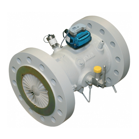
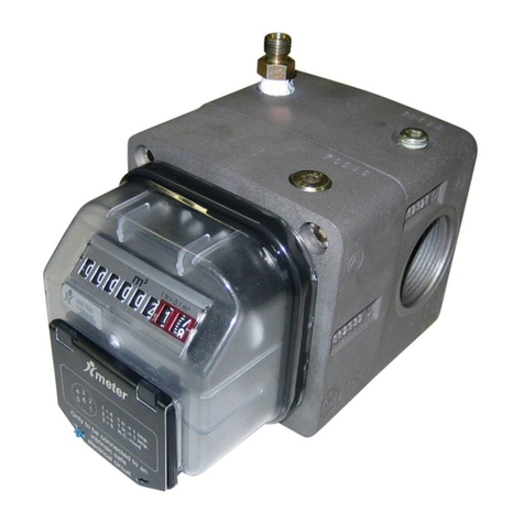
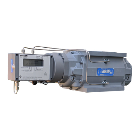
Dresser DELTA User manual

Delta® Rotary-Meters
224-099-2801
AJ: 2019/07/02
Instruction manual
Mode d’emploi
Betriebsanleitung
Istruzioni d’uso
Manual de instrucciones
Installatie voorschrift
Kullanim Kilavuzu
Manual de Instruções
Manual de instrucţiuni
Használati kézikönyv
Gas Measurement

2
D2035928-AH_EU_Declaration_DELTA.doc
EU Declaration of Conformity
Itron GmbH
Hardeckstrasse 2
D-76185 Karlsruhe
Declares under his sole responsibility that the products Rotary Meters DELTA and DELTA S-
Flow are designed and manufactured in conformity with the following Directives:
1. Directive 2014/68/EU (PED) - Modules B+D Category IV
- DIN EN 12480:2007
Certificate: DVGW CE-0085BM0420
The module D is supervised by:
#0036 TÜV SÜD Industrie Service GmbH, Westendstr. 199, D-80686 München
The used fluids are classified in group 1 according article 13.
Certificate: DGR-0036-QS-955-17
2. Directive 2014/30/EU (EMC)
- EN 60947-5-2:2007/A1:2012
- EN 61000-6-2:2005/AC:2005
- EN 61000-6-3:2007/A1:2011/AC:2012
3. Directive 2014/34/EU (ATEX)
- EN 60079-0:2012/A11:2013
- EN 60079-11:2012
- EN 13463-1:2009
- EN 13463-5:2011
Certificate: LCIE 06 ATEX 6031 X
II 1/2 G Ex ia IIC T5 Ga / Gb c T6
#0081 LCIE 33 avenue General Leclerc, F-92266 Fontenay-aux-Roses
The module D is supervised by:
#0123 TÜV SÜD Product Service GmbH, Ridlerstr. 65, D-80339 München
Certificate: EX2A 17 05 70229 004
4. Directive 2014/32/EU (MID)
- EN 12480:2002/A1:2006
Certificates: N°: DE-17-MI002-PTB001 & DE-07-MI002-PTB018
The annex D is supervised by:
#0102 Physikalisch-Technische Bundesanstalt, Bundesallee 100, D-38116 Braunschweig
Certificate: DE-M-AQ-PTB009
5. Directive 2011/65/EU (RoHS)
- EN 50581:2012
Karlsruhe, April 6
th
, 2018
K. Zinnitsch
Managing director

3
1 Characteristics. . . . . . . . . . . . . . . . . . . . . . . . . . . . . . . . . . . . . . . . . . . . . . . . . . . . . . . . . . . . . . . 4
2 Packing . . . . . . . . . . . . . . . . . . . . . . . . . . . . . . . . . . . . . . . . . . . . . . . . . . . . . . . . . . . . . . . . 4
2.1 Storage . . . . . . . . . . . . . . . . . . . . . . . . . . . . . . . . . . . . . . . . . . . . . . . . . . . . . . . . . . . . . . . . 4
2.2 Handling. . . . . . . . . . . . . . . . . . . . . . . . . . . . . . . . . . . . . . . . . . . . . . . . . . . . . . . . . . . . . . . . 4
3 Installation . . . . . . . . . . . . . . . . . . . . . . . . . . . . . . . . . . . . . . . . . . . . . . . . . . . . . . . . . . . . . . . . 4
3.1 General . . . . . . . . . . . . . . . . . . . . . . . . . . . . . . . . . . . . . . . . . . . . . . . . . . . . . . . . . . . . . . . . 4
3.2 Filtration . . . . . . . . . . . . . . . . . . . . . . . . . . . . . . . . . . . . . . . . . . . . . . . . . . . . . . . . . . . . . . . . 4
3.3 Lubrication . . . . . . . . . . . . . . . . . . . . . . . . . . . . . . . . . . . . . . . . . . . . . . . . . . . . . . . . . . . . . . 4
3.3.1 General . . . . . . . . . . . . . . . . . . . . . . . . . . . . . . . . . . . . . . . . . . . . . . . . . . . . . . . . . . . . 4
3.3.2 Choice of lubricant . . . . . . . . . . . . . . . . . . . . . . . . . . . . . . . . . . . . . . . . . . . . . . . . . . . . 4
3.3.3 Filling and draining procedure . . . . . . . . . . . . . . . . . . . . . . . . . . . . . . . . . . . . . . . . . . . . 4
4 Accessories . . . . . . . . . . . . . . . . . . . . . . . . . . . . . . . . . . . . . . . . . . . . . . . . . . . . . . . . . . . . . . . . 5
4.1 Electrical accessories . . . . . . . . . . . . . . . . . . . . . . . . . . . . . . . . . . . . . . . . . . . . . . . . . . . . . . . . 5
4.1.1 Low frequency transmitter (furnished as standard) . . . . . . . . . . . . . . . . . . . . . . . . . . . . . . . 5
4.1.2 Anti tampering. . . . . . . . . . . . . . . . . . . . . . . . . . . . . . . . . . . . . . . . . . . . . . . . . . . . . . . 5
4.1.3 Cyble sensor . . . . . . . . . . . . . . . . . . . . . . . . . . . . . . . . . . . . . . . . . . . . . . . . . . . . . . . . 5
4.1.4 Medium & high frequency transmitters (furnished as option) . . . . . . . . . . . . . . . . . . . . . . . . 5
4.2 Gasket-Filter. . . . . . . . . . . . . . . . . . . . . . . . . . . . . . . . . . . . . . . . . . . . . . . . . . . . . . . . . . . . . . 5
4.3 External dryer cartridge . . . . . . . . . . . . . . . . . . . . . . . . . . . . . . . . . . . . . . . . . . . . . . . . . . . . . . 5
4.4 Flow limiters . . . . . . . . . . . . . . . . . . . . . . . . . . . . . . . . . . . . . . . . . . . . . . . . . . . . . . . . . . . . . 5
5 Start-up . . . . . . . . . . . . . . . . . . . . . . . . . . . . . . . . . . . . . . . . . . . . . . . . . . . . . . . . . . . . . . . . 5
5.1 General . . . . . . . . . . . . . . . . . . . . . . . . . . . . . . . . . . . . . . . . . . . . . . . . . . . . . . . . . . . . . . . . 5
5.2 Installation with by-pass. . . . . . . . . . . . . . . . . . . . . . . . . . . . . . . . . . . . . . . . . . . . . . . . . . . . . . 5
5.3 Installation without by-pass . . . . . . . . . . . . . . . . . . . . . . . . . . . . . . . . . . . . . . . . . . . . . . . . . . . 6
5.4 Meters placed after a regulator . . . . . . . . . . . . . . . . . . . . . . . . . . . . . . . . . . . . . . . . . . . . . . . . . 6
6 Maintenance . . . . . . . . . . . . . . . . . . . . . . . . . . . . . . . . . . . . . . . . . . . . . . . . . . . . . . . . . . . . . . . 6
6.1 Maintenance of the meter . . . . . . . . . . . . . . . . . . . . . . . . . . . . . . . . . . . . . . . . . . . . . . . . . . . . 6
6.2 Maintenance of optional equipment . . . . . . . . . . . . . . . . . . . . . . . . . . . . . . . . . . . . . . . . . . . . . 6
6.2.1 LF and HF transmitters . . . . . . . . . . . . . . . . . . . . . . . . . . . . . . . . . . . . . . . . . . . . . . . . . . 6
6.2.2 Filter . . . . . . . . . . . . . . . . . . . . . . . . . . . . . . . . . . . . . . . . . . . . . . . . . . . . . . . . . . . . . . 6
7 Annex . . . . . . . . . . . . . . . . . . . . . . . . . . . . . . . . . . . . . . . . . . . . . . . . . . . . . . . . . . . . . . . .59

4
Keep this manual easily accessible for all users.
Ask for a written approval of the manufacturer for all cases
not planned in this instruction manual. Please respect all
national rules for installation, operation and service of gas
meters.
1 Characteristics
Delta meters are designed to measure gases of the 1st, 2nd
and 3rd gas families as specified in EN437 as well as various
filtered and non-corrosive gases (e.g. Oxygen).
2 Packing
• The meter, depending on the size or version is delivered:
• In a cardboard box, protected by carton inserts or polyeth-
ylene wedges.
On a wood pallet, protected by a cardboard cover.
The packing shall contain the filling lubricant, plugs for the
installed transmitters and this instruction manual.
2.1 Storage
If the meter is not going to be used immediately, it should
be stored under cover in a clean, dry environment, in the
horizontal position.
The caps fitted in the inlet and outlet pipe must stay in place
until installation.
2.2 Handling
The meter is delivered without lubricant in covers. Before
shipping or handling, ensure that the lubricant has been
thoroughly drained from the front and the rear covers to
prevent spillage into the measuring chamber. Meters should
be lifted only with belt around the main body or with the
eyelets.
3 Installation
3.1 General
Due to the volumetric principle of the Delta meter, its metrol-
ogy is not influenced by the installation conditions. Never-
theless the respect of the following rules will insure the best
use of your Delta meter:
Recommended installation: See Annex 1
• Check visually that the meter has not been damaged dur-
ing transport.
• No welding is allowed with meter installed.
• The meter should be installed with the impellers horizon-
tal. Allowed deviation: +/- 5°.
• Never install a meter at a low point in the piping where
the meter could be subject to the accumulation of water
or particles.
• If Teflon tape is used to tight threaded joint then the best
attention must be taken to avoid introducing tape in the
measuring chamber.
• The meter should be installed without stress in the piping.
The flanges must be correctly lined up.
• The meter should be considered in a possible grounding
system
• On flanges with UNC screw-thread, the threads are NOT
metric but defined in inch following ANSI/ASME B1.1 –
1989.
Metric threads and threads defined in inch are not
compatible!
• Please tighten bolts in opposite pairs
• A flexible coupling can be used to ensure a stress-free in-
stallation.
• The use of a filter, placed upstream of the meter, is advis-
able in gas with high particulate content. See § 3.2.
Before installation:
• The piping upstream of the meter should be free of dust.
• Remove the protective caps.
• Ensure that the direction of gas flow corresponds with the
arrow situated on the meter body.
• Check that the impellers turn freely.
• Possible accessories to be assembled onto the meter must
not interfere its corrosion protection.
3.2 Filtration
Rotary meters work better if there are no particles within the
gas. It is advisable therefore to filter the gas upstream of the
meter. Recommended level of filtration is 100 μm or better.
While the meter is in service, periodically check the cleanli-
ness of the filter, especially in the case of a new installation
or after work has been performed on the upstream piping.
For installation with flow direction from bottom to top a par-
ticular attention has to be taken to the filtering conditions to
avoid that accumulation of dust downstream of the meter
may come back into the meter. For example a second filter
can be installed downstream of the meter.
3.3 Lubrication
3.3.1 General
Choose the lubricant according to the operating conditions.
This lubricant should be neutral and non detergent. Impor-
tant:
• A lack of lubricant could cause premature wear of the me-
ter.
• An excess of lubricant can also induce problems. A surplus
of lubricant can contaminate the measuring chamber, may
degrade the metrology and cause damage to the bearings
and the impellers due to the mixture of lubricant and small
impurities contained in the gas.
• Always drain the end-covers before moving the meter.
3.3.2 Choice of lubricant
Viscosity: The viscosity has been calculated to ensure me-
chanical and metrological performance of the meter.
Commercial references: Annex 2 contains a list of commer-
cial lubricants usable for industrial gas except gases such oxy-
gen and halogens. For other gases, please consult us.
3.3.3 Filling and draining procedure
See Annex 4 for the location of fill, drain plug and sights.
Filling and draining operations should be carried out with the
meter installed in the piping, but not pressurised, though the
use of Pete’s Plugs may allow lubricant levels to be “topped
up” while the meter is pressurised (up to 20 bar). See Annex 7.

5
Both front and rear covers must be filled with lubricant, ex-
cept for the Delta Compact, SE, Evo and S1-Flow for which
only the front cover must be filled.
Adjusting the level of oil:
General case: The level is correct when it passes the centre
of the lowest sight.
Steel-bodied meters: The lubricant must be filled until it flows
out of the level point “L”
• DN50 S1-Flow: Only the front cover must be filled with oil.
4 plugs “F” or “D” are available to Fill or Drain the cover; the
lowest one must be used for draining. Depending of the
orientation of the meter, one level point “L1” or “L2” must
be used to adjust the level of oil i.e. unscrewed before the
filling. The lubricant has to be filled in “F” until it flows out
of the level point “L”, only the lowest level point must be
used to adjust the level of oil.
4 Accessories
4.1 Electrical accessories
Remarks about using the meter in potentially hazardous ar-
eas (ATEX):
• Pulse transmitters must be connected to intrinsic safe cir-
cuits, according to EN 60079-0 and EN 60079-11.
• Clean the meter head only with a damp cloth.
• All exposed aluminium parts must be suitably protected
(using paint, varnish, etc) if a film of rust is possible from
dust in the environment.
• The meter must be taken in account in the lightning risk
evaluation of the complete installation.
• Tools used for installing, removing or repairing the meter
on site must be appropriate for use in the hazardous area
bearing in mind that the hazardous area classification dur-
ing meter replacement may differ from that during normal
meter operations.
• The meter shall not be exposed to flame, ionising radiation,
ultrasound or strong electromagnetic field.
4.1.1 Low frequency transmitter (furnished as
standard)
The meter is normally delivered with a double LF pulse out-
put transmitter. The LF is a dry reed switch and is normally
open. See the name plate of the meter and Annex 4 for con-
nection information.
4.1.2 Anti tampering
The meter is delivered as standard with an anti tampering
switch. It is a dry reed switch and is normally closed. See the
name plate of the meter for connection details.
4.1.3 Cyble sensor
A Cyble sensor can be installed onto the totaliser at any time,
see Annex 4. The Cyble sensor is a bounce-free transmitter. It
allows also the counting of eventual back flows.
4.1.4 Medium & high frequency transmitters
(furnished as option)
The meter can be delivered with medium or high frequency
transmitters. There are inductive sensors, and connection is
to a NAMUR- type input circuit (EN 60947-5-6).
4.2 Gasket-Filter
A “Gasket-filter” can be inserted directly upstream of flanged
meters at the place of the standard gasket: it is a protection
against particles remaining in the upstream pipe. It is recom-
mended to remove it after approximately 4 to 8 weeks of
operation.
4.3 External dryer cartridge
The meter can be equipped with an external silicagel car-
tridge for installation in severe environment conditions. To
replace the cartridge, unscrew the old cartridge, remove the
protective plug of the new cartridge and screw it into the
totaliser.
4.4 Flow limiters
Flow limiters are recommended to be used to protect the
meter against over-flows or pressure pulses caused by not
perfect installation layout
5 Start-up
5.1 General
The procedure of start-up is always dependent on the instal-
lation configuration.
Before pressurising the meter, the lubrication procedure
should be performed. Pressurisation or depressurisation
should be carried out with very low pressure change. The
pressure change should not exceed 0.3 bar/5 P.S.I. per sec-
ond.
After start-up, please check the tightness of the installation.
The proper installation and functioning of the meter can
be verified by a visual control of the totaliser (to check that
the meter runs properly) and by measuring its pressure loss
while running though the use of Pete’s Plugs may allow this
pressure loss to be measured while the meter is pressurised
(up to 20 bar).
5.2 Installation with by-pass:
See Annex 5
START-UP:
Begin with all valves closed.
• Slowly open the by-pass valve to pressurise the down-
stream piping.
• When the pressure is balanced downstream, slowly open
the small upstream valve V1. The pressure variation should
not exceed 0.3 bar per second.
• When the pressure is balanced in the meter, slowly open
the main upstream valve and then close V1.
• Slowly open the downstream valve and check that the me-
ter starts to register the flow.

6
• Gradually, close the by-pass valve. Check that the flow rate
doesn’t exceed the capacity of the meter.
SHUT DOWN:
• Slowly open the by-pass valve and then close the up-
stream and downstream valves on the meter line.
• Carefully open the small bleeder valve V2 and depressurise
the meter. The pressure variation should not exceed 0.3
bar per second.
• Some gas still inside the meter and the pipe, therefore suf-
ficient ventilation is required.
5.3 Installation without by-pass: See Annex 6
START-UP:
Begin with all valves closed.
• Slightly open the upstream valve to pressurise the meter
line. The pressure variation should not exceed 0.3 bar per
second. When the pressure is balanced, fully open the up-
stream valve.
• Slightly open the downstream valve. The valve should be
opened a small amount to maintain:
- The upstream pressure in the meter line.
– A low flow rate in the meter during the downstream
pressurisation (approx. 5% Qmax).
When the downstream pressure is balanced, the down-
stream valve can be completely opened.
SHUT DOWN:
• Very slowly close the downstream valve and check that the
meter is no longer recording.
• Close the upstream valve.
• Slowly open the small bleed valve V2. The pressure varia-
tion should not exceed 0.3 bar per second.
• Some gas still inside the meter and the pipe, therefore suf-
ficient ventilation is required.
5.4 Meters placed after a regulator
Installation has to be done in accordance with the technical
manual of the specific regulator. During pressurisation and
depressurisation, insure that the pressure variation should
not exceed 0.3 bar per second.
6 Maintenance
6.1 Maintenance of the meter
Once installed, the meter does not require any specific at-
tention except a periodical check or change of the lubricant
filled in the covers.
After start-up:
Natural gas: After the preliminary term of service, the lubri-
cant level should be checked.
Other gases: After a working period of 100 hours from com-
missioning, the lubricant level should be checked.
If the lubricant level is appreciably low, if the lubricant is
emulsified or if there is a chemical reaction between the lu-
bricant and the gas, the lubricant should be reassessed and
changed to fit the prevailing conditions.
Periodical change of lubricant:
The period between checks or changes of lubricant depends
of the operating conditions (pressure variation, flow rate...).
Natural gas: Under normal conditions, lubricant has to be
changed every 5 to 8 years. When the meter is used with
extremely clean gas the period can be extended.
Other gases: Please consult us.
Use solvent and alcohol free product to clean the meter.
Repair must be done only by qualified personal. Afterwards a
tightness test with 1.1 x PS (Pmax) must be performed.
If used with wet gas, internal and external effect of corrosion
has to be checked regularly and in case of severe corrosion,
the meter has to be replaced.
Spare parts:
When changing pressure containing parts, ensure that spare
parts that comply with the PED are used.
6.2 Maintenance of optional equipment
6.2.1 LF and HF transmitters
These transmitters do not require any specific maintenance.
The function of the transmitters can be checked by compar-
ing the electronic index with the meter index.
6.2.2 Filter
If an increase of pressure loss is noticed, the filter should be
checked and cleaned/replaced before any maintenance on
the meter.

7
D2035928-AH_EU_Declaration_DELTA.doc
Déclaration de Conformité UE
Itron GmbH
Hardeckstrasse 2
D-76185 Karlsruhe
Déclare en sa seule responsabilité que les produits Compteurs à pistons rotatifs DELTA et
DELTA S-Flow sont conçus et fabriqués en conformité avec les Directives suivantes :
1. 2014/68/UE Modules B+D Catégorie IV –DESP
- DIN EN 12480:2007
Avec certificat d’approbation de type n° : DVGW CE-0085BM0420
Le module D est supervisé par :
TÜV SÜD Industrie Service GmbH (CE: 0036); Westendstr. 199, D-80686 München
Les fluides utilisés sont classifiés en groupe 1 suivant l´article 13.
Certificat d’approbation de type n° :DGR-0036-QS-955-17
2. 2014/30/UE (CEM)
- EN 60947-5-2:2007/A1:2012
- EN 61000-6-2:2005/AC:2005
- EN 61000-6-3:2007/A1:2011/AC:2012
3. 2014/34/UE (ATEX)
- EN 60079-0:2012/A11:2013
- EN 60079-11:2012
- EN 13463-1:2009
- EN 13463-5:2011
Avec certificat d’approbation de type n° :LCIE 06 ATEX 6031
II 1/2 G Ex ia IIC T5 Ga / Gb c T6
#0081 LCIE 33 avenue General Leclerc, F-92266 Fontenay-aux-Roses
Le module D (Annexe IV) est supervisé par :
#0123 TÜV SÜD Product Service GmbH, Ridlerstr. 65, D-80339 München
Avec certificat d’approbation de type n° : EX2A 17 05 70229 004
4. 2014/32/UE (MID)
- EN 12480:2002/A1:2006
Annexe B avec certificat d’approbation de type :
N°: DE-17-MI002-PTB001 & DE-07-MI002-PTB018
L’annexe D est supervisée par :
Physikalisch-Technische Bundesanstalt (CE: 0102), Bundesallee 100, D-38116 Braunschweig
Avec certificat d’approbation de type n° :DE-M-AQ-PTB009
5. 2011/65/UE (RoHS)
- EN 50581:2012
Karlsruhe, 6 avril 2018
K. Zinnitsch
Directeur général

8
1 Caractéristiques. . . . . . . . . . . . . . . . . . . . . . . . . . . . . . . . . . . . . . . . . . . . . . . . . . . . . . . . . . . . . . 9
2 Emballage . . . . . . . . . . . . . . . . . . . . . . . . . . . . . . . . . . . . . . . . . . . . . . . . . . . . . . . . . . . . . . . . 9
2.1 Stockage . . . . . . . . . . . . . . . . . . . . . . . . . . . . . . . . . . . . . . . . . . . . . . . . . . . . . . . . . . . . . . . 9
2.2 Manutention . . . . . . . . . . . . . . . . . . . . . . . . . . . . . . . . . . . . . . . . . . . . . . . . . . . . . . . . . . . . . 9
3 Installation . . . . . . . . . . . . . . . . . . . . . . . . . . . . . . . . . . . . . . . . . . . . . . . . . . . . . . . . . . . . . . . . 9
3.1 Généralités . . . . . . . . . . . . . . . . . . . . . . . . . . . . . . . . . . . . . . . . . . . . . . . . . . . . . . . . . . . . . . 9
3.2 Filtration 9
3.3 Lubrification . . . . . . . . . . . . . . . . . . . . . . . . . . . . . . . . . . . . . . . . . . . . . . . . . . . . . . . . . . . . . 9
3.3.1 Généralités . . . . . . . . . . . . . . . . . . . . . . . . . . . . . . . . . . . . . . . . . . . . . . . . . . . . . . . . . 9
3.3.2 Choix du lubrifiant. . . . . . . . . . . . . . . . . . . . . . . . . . . . . . . . . . . . . . . . . . . . . . . . . . . . . 9
3.3.3 Remplissage et vidange . . . . . . . . . . . . . . . . . . . . . . . . . . . . . . . . . . . . . . . . . . . . . . . . .10
4 Accessoires . . . . . . . . . . . . . . . . . . . . . . . . . . . . . . . . . . . . . . . . . . . . . . . . . . . . . . . . . . . . . . . .11
4.1 Accessoires électriques . . . . . . . . . . . . . . . . . . . . . . . . . . . . . . . . . . . . . . . . . . . . . . . . . . . . . .10
4.1.1 Emetteur basse fréquence (équipement standard) . . . . . . . . . . . . . . . . . . . . . . . . . . . . . . .10
4.1.2 Surveillance de ligne . . . . . . . . . . . . . . . . . . . . . . . . . . . . . . . . . . . . . . . . . . . . . . . . . . .10
4.1.3 Capteur Cyble . . . . . . . . . . . . . . . . . . . . . . . . . . . . . . . . . . . . . . . . . . . . . . . . . . . . . . .10
4.1.4 Emetteurs à moyenne & haute fréquence (disponible en option) . . . . . . . . . . . . . . . . . . . . .10
4.2 Joint filtre . . . . . . . . . . . . . . . . . . . . . . . . . . . . . . . . . . . . . . . . . . . . . . . . . . . . . . . . . . . . . . .10
4.3 Cartouche silicagel externe . . . . . . . . . . . . . . . . . . . . . . . . . . . . . . . . . . . . . . . . . . . . . . . . . . .10
4.4 Limiteurs de débit. . . . . . . . . . . . . . . . . . . . . . . . . . . . . . . . . . . . . . . . . . . . . . . . . . . . . . . . . .10
5 Mise en service . . . . . . . . . . . . . . . . . . . . . . . . . . . . . . . . . . . . . . . . . . . . . . . . . . . . . . . . . . . . . .10
5.1 Généralités . . . . . . . . . . . . . . . . . . . . . . . . . . . . . . . . . . . . . . . . . . . . . . . . . . . . . . . . . . . . . .10
5.2 Installation avec bi-pass . . . . . . . . . . . . . . . . . . . . . . . . . . . . . . . . . . . . . . . . . . . . . . . . . . . . . .11
5.3 Installation sans bi-pass . . . . . . . . . . . . . . . . . . . . . . . . . . . . . . . . . . . . . . . . . . . . . . . . . . . . . .11
5.4 Compteurs placés après un régulateur . . . . . . . . . . . . . . . . . . . . . . . . . . . . . . . . . . . . . . . . . . . .11
6 Entretien . . . . . . . . . . . . . . . . . . . . . . . . . . . . . . . . . . . . . . . . . . . . . . . . . . . . . . . . . . . . . . . .11
6.1 Entretien du compteur . . . . . . . . . . . . . . . . . . . . . . . . . . . . . . . . . . . . . . . . . . . . . . . . . . . . . .11
6.2 Entretien de l’équipement disponible en option . . . . . . . . . . . . . . . . . . . . . . . . . . . . . . . . . . . . .11
6.2.1 Emetteurs BF et HF . . . . . . . . . . . . . . . . . . . . . . . . . . . . . . . . . . . . . . . . . . . . . . . . . . . .11
6.2.2 Filtre . . . . . . . . . . . . . . . . . . . . . . . . . . . . . . . . . . . . . . . . . . . . . . . . . . . . . . . . . . . . . .11
7 Annexes . . . . . . . . . . . . . . . . . . . . . . . . . . . . . . . . . . . . . . . . . . . . . . . . . . . . . . . . . . . . . . . .59

9
Veuillez conserver ce mode d’emploi accessible pour tous les
utilisateurs. Demander l’accord écrit du fabricant pour tous
les cas non prévus dans le présent mode d’emploi. Veuillez
respecter toutes les réglementations nationales pour l’instal-
lation, l’utilisation et la maintenance des compteurs de gaz.
1 Caractéristiques
Les compteurs Delta sont conçus pour mesurer les gaz des
1er, 2eme et 3eme familles comme définies dans l´EN437
ainsi que de nombreux gaz filtrés et non corrosifs (par
exemple Oxygène).
2 Emballage
En fonction de la taille ou de la version, le compteur est livré :
Dans un carton individuel, protégé par un calage en carton
ou polyéthylène.
Sur une palette en bois protégé par une coiffe en carton.
L’emballage contient le lubrifiant, les prises pour les émet-
teurs d’impulsion installés et le présent manuel.
2.1 Stockage
Si le compteur n’est pas utilisé dans l’immédiat, il doit être
protégé et entreposé en position horizontale dans un lieu
propre et sec. Les obturateurs placés dans les orifices d’en-
trée et de sortie doivent rester en place jusqu’à l’installation
du compteur sur la canalisation.
2.2 Manutention
Le compteur est fourni sans lubrifiant dans les carters. Avant
toute expédition ou manutention, il faut vous assurer que
le lubrifiant a été complètement vidangé des carters avant
et arrière de façon à éviter un déversement intempestif du
lubrifiant dans la chambre de mesure. Le compteur peut être
manipulé à l’aide de câbles passés sous le corps ou dans les
anneaux de levage uniquement.
3 Installation
3.1 Généralités
Le compteur doit impérativement être installé dans un
environnement dont les conditions limites (en particulier
pression, température, débit,...) sont compatibles avec ses
caractéristiques propres indiquées sur la plaque signalétique.
Compte tenu du principe volumétrique du compteur Delta,
sa métrologie n’est pas influencée par les conditions d’instal-
lation. Néanmoins, pour garantir le bon fonctionnement du
compteur, les instructions suivantes devront être respectées
: voir l’annexe 1.
• Vérifier visuellement que le compteur n’a pas été endom-
magé durant le transport.
• Les opérations de soudures sur la canalisation ne sont pas
autorisées lorsque le compteur est installé.
• Le compteur devra être installé avec les pistons à l‘horizon-
tale. Déviation permise : +/- 5°.
• Ne jamais installer un compteur à un point bas d‘une instal-
lation où il pourrait être soumis à une accumulation d‘eau
ou de particules.
• L´utilisation de bande téflon sur les raccords filetés doit
être faite avec beaucoup de précaution de manière à éviter
d´en introduire dans la chambre de mesure.
• Le compteur doit être installé sans contraintes sur la canali-
sation. Les brides doivent être alignées correctement.
• Le compteur doit être considéré dans un système possi-
blement mis à la terre.
• Les brides avec UNC sont livrées avec des taraudages défi-
nis en pouces suivant ANSI/ASME B1.1.
Les filetages/taraudages métriques et UNC ne sont
pas compatibles !
• Un accouplement souple peut être utilisé pour assurer une
installation sans contraintes.
• L’utilisation d’un filtre placé en amont du compteur est
conseillée pour des gaz qui présentent un contenu parti-
culaire élevé. Voir § 3.2
Avant l´installation:
• S’assurer que la canalisation en amont du compteur est
exempte de poussières.
• Enlever les obturateurs placés dans les orifices d’entrée et
de sortie.
• S’assurer que le sens d´écoulement du gaz correspond à la
flèche située sur le compteur.
• S’assurer que les pistons tournent librement.
• Les accessoires qui pourraient être assemblés sur le comp-
teur ne doivent pas interférer avec sa protection contre la
corrosion.
3.2 Filtration
Les compteurs à pistons rotatifs fonctionnent mieux si le gaz
ne contient pas de particules. Par conséquent, il est conseillé
de filtrer le gaz en amont du compteur. Le niveau de filtration
recommandé est d’au moins 100 μm. Lorsque le compteur
est en service, il faut vérifier périodiquement la propreté du
filtre, notamment dans le cas d’une nouvelle installation ou
après l’exécution de travaux sur la tuyauterie en amont du
compteur.
Dans le cas d´une installation ayant une direction du gaz du
bas vers le haut, il faut particulièrement faire attention à la fil-
tration de manière à éviter que des poussières accumulées à
l´aval ne retombe dans le compteur. Par exemple, un second
filtre peut être installé à l´aval du compteur.
3.3 Lubrification
3.3.1 Généralités
Choisir le lubrifiant en fonction des conditions d’exploitation.
Le lubrifiant doit être neutre et non détergent. Important :
• Une lubrification insuffisante peut causer une usure pré-
maturée du compteur.
• Une lubrification excessive peut également entraîner des
problèmes. Un surplus de lubrifiant peut contaminer la
chambre de mesure, détériorer la métrologie et occasion-
ner des dommages sur les paliers et les pistons en raison
du mélange du lubrifiant et des impuretés contenues dans
le gaz.
• Toujours vidanger les carters avant le transport du comp-
teur.

10
3.3.2 Choix du lubrifiant
Viscosité : la viscosité a été calculée pour assurer la meilleure
performance mécanique et métrologique du compteur.
Références commerciales : L’annexe 2 contient une liste de
lubrifiants du commerce. Ils peuvent être utilisés pour les
gaz industriels, à l’exception des gaz tels qu’oxygène et ha-
logènes. En cas d’utilisation avec d’autres gaz, veuillez nous
consulter.
3.3.3 Remplissage et vidange
Voir l’annexe 3 pour l’emplacement des bouchons de rem-
plissage, de vidange et des voyants de niveau de lubrifiant.
Avant l’installation: Les opérations de remplissage et de
vidange doivent être effectuées lorsque le compteur est
installé sur la conduite, sans pression. L’utilisation de Pete’s
Plugs permet de réaliser les niveaux de lubrifiant alors que le
compteur est sous pression (jusqu’à 20 bars). Voir l’annexe7.
Les niveaux de lubrifiant doivent être effectués dans les car-
ters avant et arrière sauf pour le Delta Conpact, SE, Evo et le
S1-Flow pour lesquels seul le niveau dans le carter avant est
à réaliser.
Comment effectuer la mise à niveau de lubrifiant:
Cas général: Le niveau est correct quand il atteint le centre
du voyant placé le plus bas.
Compteurs en acier: Le bouchon de niveau “L” est utilisé
comme trop plein.
• DN50 S1-Flow: Le niveau s´effectue uniquement dans le
carter avant. 4 bouchons “F” ou “D” sont à utiliser pour rem-
plir ou vidanger le carter; le bouchon placé le plus bas sert
à vidanger. En fonction de l´orientation du compteur le
niveau “L1” ou “L2” doit être dévissé avant le remplissage.
Le lubrifiant est injecté dans “F” jusqu´à ce qu´il déborde
par le niveau “L”; seul le niveau placé le plus bas est à utiliser
pour faire la mise à niveau.
4 Accessoires
4.1 Accessoires électriques
Instructions pour l’utilisation en atmosphères potentielle-
ment explosives (ATEX) :
• Les émetteurs d‘impulsions ne doivent être raccordés qu‘à
des appareils homologués de sécurité intrinsèque suivant
l‘EN 60079-0 et l’EN 60079-11.
• Nettoyer le totalisateur uniquement avec un chiffon hu-
mide.
• La surface extérieure des pièces en aluminium situées dans
les environs immédiats du compteur doit être protégée
par un traitement adéquat (par exemple peinture) si une
pellicule oxydée peut s‘y déposer.
• Le compteur doit être pris en compte dans l´évaluation du
risque de foudre de l´ensemble de l´installation.
• Pour le montage, démontage ou réparation sur site du
compteur, uniquement des outils autorisés d‘emploi en
zone explosive peuvent être utilisés.
• Le compteur ne doit pas être exposé aux flammes, radia-
tions ionisantes, ultrasons ou à des champs électromagné-
tiques puissants.
4.1.1 Emetteur basse fréquence (équipement
standard)
Le compteur est livré avec un double émetteur d’impulsions
à basse fréquence. L´émetteur BF est constitué d´une am-
poule Reed à contact sec normalement ouvert. Le schéma
de câblage est indiqué sur la plaque signalétique du comp-
teur. Voir aussi l’annexe 4 pour de plus amples informations.
4.1.2 Surveillance de ligne
Le compteur est livré en standard avec un contact de sur-
veillance de ligne. Il s’agit d’une ampoule Reed à contact sec
normalement fermé. Le schéma de câblage est indiqué sur
la plaque signalétique du compteur.
4.1.3 Capteur Cyble
Le capteur Cyble peut être installé à n´importe quel moment
sur le totalisateur, voir l´annexe 4. Le capteur Cyble est un
émetteur d´impulsion sans rebond qui permet aussi de
prendre en compte les débits inverses éventuels.
4.1.4 Emetteurs à moyenne & haute fréquence
(disponible en option)
Le compteur peut être livré avec des émetteurs à moyenne
ou haute fréquence, de type inductif. Le branchement s’ef-
fectue sur un appareil possédant un circuit d´entrée de type
NAMUR (EN 60947-5-6).
4.2 Joint filtre
Pour les compteurs équipés de brides, un joint filtre peut
être inséré directement en amont du compteur à la place
du joint d’étanchéité standard. Ce filtre protège le compteur
contre les impuretés restantes dans la tubulure amont. Il est
recommandé de le retirer après 4 à 8 semaines d´utilisation.
4.3 Cartouche silicagel externe
Le compteur peut être équipé en option d’une cartouche sili-
cagel externe pour les installations dans les environnements
difficiles. Pour remplacer la cartouche, dévisser l’ancienne,
enlever l’opercule de protection de la nouvelle et la revisser
dans le totalisateur.
4.4 Limiteurs de débit
Il est recommandé d’utiliser des limiteurs de débit afin de
protéger le compteur contre des surpressions qui seraient
provoquées par une conception perfectible de l’installation.
5 Mise en service
5.1 Généralités
La procédure de mise en service dépend toujours de la confi-
guration de l’installation. Avant de mettre le compteur sous
pression, le niveau de lubrifiant doit être effectué. La pressuri-
sation ou dépressurisation doit être effectuée graduellement
: 0.3 bars / 5 P.S.I. par seconde au maximum.
Après mise en service, l’étanchéité de l’installation doit être
vérifiée.

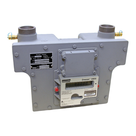
11
La bonne installation et le bon fonctionnement du compteur
peuventêtrevérifiés paruncontrol visueldutotalisateur(pour
vérifier que le compteur tourne correctement) ainsi que par
la mesure de la perte de charge du compteur en fonction-
nement. L’utilisation de Pete’s Plugs permet de réaliser cette
mesure alors que le compteur est sous pression (jusqu’à 20
bars).
5.2 Installation avec bi-pass :
voir l’annexe 5
MISE EN SERVICE :
• Procéder à la mise en service toutes vannes fermées.
• Ouvrir lentement la vanne de bi-pass de façon à pressuriser
la tuyauterie aval.
• Lorsque la pression est équilibrée en aval, ouvrir lentement
le robinet V1. Les variations de pression ne doivent pas dé-
passer 0.3 bars par seconde.
• Lorsque la pression est équilibrée dans le compteur, ouvrir
lentement la vanne principale amont, puis fermer V1.
• Ouvrir lentement la vanne aval et s‘assurer que le comp-
teur commence à enregistrer le débit.
• Fermer progressivement la vanne de bi-pass. Vérifier que le
débit ne dépasse pas la capacité du compteur.
MISE HORS SERVICE :
• Ouvrir lentement la vanne de bi-pass puis fermer les
vannes en amont et en aval du compteur.
• Ouvrir légèrement le robinet V2 et dépressuriser le comp-
teur. Les variations de pression ne doivent pas dépasser
0.3 bars par seconde. S´assurer de la dépressurisation com-
plète du compteur.
• Du gaz peut rester dans le compteur ou la canalisation,
c‘est pourquoi une ventilation suffisante est nécessaire.
5.3 Installation sans bi-pass :
voir l’annexe 6
MISE EN SERVICE :
Procéder à la mise en service toutes vannes fermées.
• Ouvrir lentement la vanne amont de façon à pressuriser le
compteur. Les variations de pression ne doivent pas dé-
passer 0.3 bars par seconde. Lorsque la pression est équili-
brée, ouvrir entièrement la vanne amont.
• Ouvrir lentement la vanne aval. La vanne doit être légère-
ment ouverte pour maintenir :
– la pression amont dans le compteur.
– Un débit faible dans le compteur pendant la pressurisa-
tion (approx. 5% Qmax).
Lorsque la pression aval est équilibrée, la vanne aval peut être
entièrement ouverte.
MISE HORS SERVICE :
• Fermer la vanne aval très lentement et vérifier que le
compteur n’enregistre plus de débit.
• Fermer la vanne amont.
• Ouvrir lentement le robinet V2. Les variations de pression
ne doivent pas dépasser 0.3 bars par seconde. S’assurer de
la dépressurisation complète du compteur.
Du gaz peut rester dans le compteur ou la canalisation, c‘est
pourquoi une ventilation suffisante est nécessaire.
5.4 Compteurs placés après un régulateur
L’installation doit être effectuée conformément au manuel
technique spécifique du régulateur. Lors de la pressurisation
ou de la dépressurisation, il faut veiller à ce que les variations
de pression ne dépassent pas 0.3 bars par seconde.
6 Entretien
6.1 Entretien du compteur
Une fois installé, le compteur ne nécessite pas d´attention
particulière, hormis un suivi périodique du lubrifiant contenu
dans les carters.
Après la mise en service :
Gaz naturel : après quelques jours de service, le niveau du
lubrifiant doit être vérifié.
Autres gaz : après une période de fonctionnement de 100
heures à compter de la mise en service, le niveau de lubrifiant
doit être contrôlé.
Si le niveau du lubrifiant est sensiblement bas, si le lubrifiant
est émulsifié ou en cas de réaction chimique entre le lubri-
fiant et le gaz, les caractéristiques du lubrifiant doivent être
changées. Période de remplacement du lubrifiant :
La période entre les contrôles ou les remplacements du lu-
brifiant dépend des conditions d’exploitation (variations de
pression, débit…).
Gaz naturel : dans des conditions d’utilisation normale, le lu-
brifiant doit être remplacé tous les 5 à 8 ans. Si le compteur
est utilisé avec un gaz extrêmement propre, cette durée peut
être augmentée.
Autres gaz : veuillez nous consulter.
Utiliser un produit sans solvant ni alcool pour nettoyer le
compteur.
La réparation ne doit être effectué que par du personnel qua-
lifié. Après réparation, un essai d’étanchéité à 1,1 x PS (Pmax)
doit être effectué.
En cas d’utilisation avec des gaz humides, les effets de la cor-
rosion doivent être périodiquement vérifiés. En cas de corro-
sion importante, le compteur doit être remplacé.
Pièces détachées:
Lorsqu’une pièce sous pression est changée, il faut s’assurer
que la pièce détachée est conforme à la PED.
6.2 Entretien de l’équipement disponible en
option
6.2.1 Emetteurs BF et HF
Ces émetteurs ne nécessitent pas d’entretien spécifique. Le
fonctionnement des émetteurs peut être contrôlé en com-
parant l’index du correcteur et l’index du compteur.
6.2.2 Filtre
Si une augmentation de la perte de pression est constatée, le
filtre doit être contrôlé et nettoyé ou remplacé avant d’effec-
tuer des opérations d’entretien sur le compteur.

12
D2035928-AH_EU_Declaration_DELTA.doc
EU - Konformitätserklärung
Itron GmbH
Hardeckstrasse 2
D-76185 Karlsruhe
Erklärt in alleiniger Verantwortung, dass die Drehkolbenzählerbaureihen DELTA und DELTA
S-Flow entsprechend den nachfolgenden Vorschriften konstruiert und hergestellt sind:
1. Richtlinie 2014/68/EU (DGRL) Modul B+D Kategorie IV
- DIN EN 12480:2007
EG-Baumusterprüfbescheinigung Nr.: DVGW CE-0085BM0420
Das Modul D wird überwacht durch:
TÜV SÜD Industrie Service GmbH (CE: 0036); Westendstr. 199, D-80686 München
Die Einstufung der Fluide erfolgte gemäß Artikel 13 in Stoffgruppe 1.
EG Zertifikate Nr.: DGR-0036-QS-955-17
2. Richtlinie 2014/30/EG (EMV)
- EN 60947-5-2:2007/A1:2012
- EN 61000-6-2:2005/AC:2005
- EN 61000-6-3:2007/A1:2011/AC:2012
3. Richtlinie 2014/34/EG (ATEX)
- EN 60079-0:2012/A11:2013
- EN 60079-11:2012
- EN 13463-1:2009
- EN 13463-5:2011
mit EG Baumusterprüfungszertifikat Nr.: LCIE 06 ATEX 6031 X
II 1/2 G Ex ia IIC T5 Ga / Gb c T6
#0081 LCIE 33 avenue General Leclerc, F-92266 Fontenay-aux-Roses
Das Modul D (Anhang IV) wird überwacht durch:
#0123 TÜV SÜD Product Service GmbH, Ridlerstr. 65, D-80339 München
EG Zertifikate Nr.: EX2A 17 05 70229 004
4. Richtlinie 2014/32/EG (MID)
- EN 12480:2002/A1:2006
Anhang B mit EG Baumusterprüfungszertifikate:
Nr.: DE-17-MI002-PTB001 & DE-07-MI002-PTB018
Anhang D wird überwacht durch:
Physikalisch-Technische Bundesanstalt (CE: 0102), Bundesallee 100, D-38116 Braunschweig
EG Zertifikate Nr.: DE-M-AQ-PTB009
5. Richtlinie 2011/65/EG (RoHS)
- EN 50581:2012
Karlsruhe, 6. April 2018
K. Zinnitsch
Geschäftsführer

13
1 Eigenschaften: . . . . . . . . . . . . . . . . . . . . . . . . . . . . . . . . . . . . . . . . . . . . . . . . . . . . . . . . . . . . . .14
2 Verpackung . . . . . . . . . . . . . . . . . . . . . . . . . . . . . . . . . . . . . . . . . . . . . . . . . . . . . . . . . . . . . . . .14
2.1 Lagerung . . . . . . . . . . . . . . . . . . . . . . . . . . . . . . . . . . . . . . . . . . . . . . . . . . . . . . . . . . . . . . .14
2.2 Handhabung . . . . . . . . . . . . . . . . . . . . . . . . . . . . . . . . . . . . . . . . . . . . . . . . . . . . . . . . . . . .14
3 Installation . . . . . . . . . . . . . . . . . . . . . . . . . . . . . . . . . . . . . . . . . . . . . . . . . . . . . . . . . . . . . . . .14
3.1 Allgemein . . . . . . . . . . . . . . . . . . . . . . . . . . . . . . . . . . . . . . . . . . . . . . . . . . . . . . . . . . . . . . .14
3.2 Filtration 14
3.3 Schmierung . . . . . . . . . . . . . . . . . . . . . . . . . . . . . . . . . . . . . . . . . . . . . . . . . . . . . . . . . . . . .14
3.3.1 Allgemein . . . . . . . . . . . . . . . . . . . . . . . . . . . . . . . . . . . . . . . . . . . . . . . . . . . . . . . . . .14
3.3.2 Schmiermittelwahl . . . . . . . . . . . . . . . . . . . . . . . . . . . . . . . . . . . . . . . . . . . . . . . . . . . .14
3.3.3 Vorgehensweise zum Befüllen- und Ablassen von Öl . . . . . . . . . . . . . . . . . . . . . . . . . . . . .15
4 Zubehör . . . . . . . . . . . . . . . . . . . . . . . . . . . . . . . . . . . . . . . . . . . . . . . . . . . . . . . . . . . . . . . .15
4.1 Elektrisches Zubehör . . . . . . . . . . . . . . . . . . . . . . . . . . . . . . . . . . . . . . . . . . . . . . . . . . . . . . .15
4.1.1 Niederfrequenter Impulsgeber (Standardausstattung) . . . . . . . . . . . . . . . . . . . . . . . . . . . .15
4.1.2 Anti-Manipulationskontakt . . . . . . . . . . . . . . . . . . . . . . . . . . . . . . . . . . . . . . . . . . . . . . .15
4.1.3 Cyble-Sensor . . . . . . . . . . . . . . . . . . . . . . . . . . . . . . . . . . . . . . . . . . . . . . . . . . . . . . . .15
4.1.4 Mittel- und Hochfrequenzimpulsgeber (optional) . . . . . . . . . . . . . . . . . . . . . . . . . . . . . . .15
4.2 Flachsieb . . . . . . . . . . . . . . . . . . . . . . . . . . . . . . . . . . . . . . . . . . . . . . . . . . . . . . . . . . . . . . .15
4.3 Externe Trockenpatrone für das Zählwerk . . . . . . . . . . . . . . . . . . . . . . . . . . . . . . . . . . . . . . . . . .15
4.4 Durchflussbegrenzer . . . . . . . . . . . . . . . . . . . . . . . . . . . . . . . . . . . . . . . . . . . . . . . . . . . . . . . .15
5 Inbetriebnahme . . . . . . . . . . . . . . . . . . . . . . . . . . . . . . . . . . . . . . . . . . . . . . . . . . . . . . . . . . . . .15
5.1 Allgemein . . . . . . . . . . . . . . . . . . . . . . . . . . . . . . . . . . . . . . . . . . . . . . . . . . . . . . . . . . . . . . .15
5.2 Installation mit Bypass . . . . . . . . . . . . . . . . . . . . . . . . . . . . . . . . . . . . . . . . . . . . . . . . . . . . . . .16
5.3 Installation ohne Bypass . . . . . . . . . . . . . . . . . . . . . . . . . . . . . . . . . . . . . . . . . . . . . . . . . . . . .16
5.4 Messgeräte nach einem Regler . . . . . . . . . . . . . . . . . . . . . . . . . . . . . . . . . . . . . . . . . . . . . . . . .16
6 Wartung . . . . . . . . . . . . . . . . . . . . . . . . . . . . . . . . . . . . . . . . . . . . . . . . . . . . . . . . . . . . . . . .16
6.1 Wartung des Messgerätes . . . . . . . . . . . . . . . . . . . . . . . . . . . . . . . . . . . . . . . . . . . . . . . . . . . .16
6.2 Wartung der optionalen Ausrüstung . . . . . . . . . . . . . . . . . . . . . . . . . . . . . . . . . . . . . . . . . . . . .16
6.2.1 RK und HF Impulsgeber . . . . . . . . . . . . . . . . . . . . . . . . . . . . . . . . . . . . . . . . . . . . . . . . .16
6.2.2 Filter . . . . . . . . . . . . . . . . . . . . . . . . . . . . . . . . . . . . . . . . . . . . . . . . . . . . . . . . . . . . . .16
7 Technische Daten . . . . . . . . . . . . . . . . . . . . . . . . . . . . . . . . . . . . . . . . . . . . . . . . . . . . . . . . . . . .59

14
Dieses Dokument muss für alle befugten Personen leicht zu-
gänglich aufbewahrt werden.
Fordern Sie eine schriftliche Bestätigung für alle nicht in die-
ser Betriebsanleitung aufgeführten Beschreibungen an. Bitte
unbedingt die nationalen gültigen Regeln und Normen be-
achten.
1 Eigenschaften:
Der Drehkolbenzähler Delta eignet sich zur Messung aller
Gase der 1., 2. und 3. Familie entsprechende EN437 sowie allen
anderen gefilterten und nicht-korrosiven Gase (z.B. Sauerstoff).
2 Verpackung
Das Messgerät wird abhängig von Größe oder Version wie
folgt geliefert:
• In einem Hartpapierkarton, geschützt durch Einlagen aus
Karton oder Polyethylen.
• Auf einer Holzpalette, geschützt durch eine Hartpapierab-
deckung.
Die Verpackung muss das Befüllschmiermittel beinhalten, Ste-
cker für die installierten Impulsgeber und dieses Handbuch.
2.1 Lagerung
Wird das Messgerät nicht sofort verwendet, so soll-
te es in einer sauberen, trockenen Umgebung
und in horizontaler Position gelagert werden.
Die Abdeckungen am Einlass- und Auslassrohr müssen bis zur
Installation montiert bleiben.
2.2 Handhabung
Das Messgerät wird ohne Schmiermittel in den Ölkammern
geliefert. Bei Transport nach erfolgter Befüllung mit Schmier-
mittel (z.B. zum Zwecke der Nacheichung) ist sicherzustellen,
dass das Schmiermittel vor Versand oder Handhabung voll-
ständig aus der vorderen und hinteren Ölkammer abgelassen
wurde, um ein Eindringen des Schmiermittels in die Mess-
kammer zu vermeiden. Die Zähler dürfen nur mit geeigneten
Traghilfen (Riemen) am Gehäuse oder an den Ringschrauben
angehoben werden.
3 Installation
3.1 Allgemein
Durch das volumetrische Messprinzip des Delta-Zählers wird
dessen Metrologie nicht durch die Installationsbedingungen
beeinflusst.TrotzdemgewährleistetdieEinhaltungderfolgen-
den Regeln eine bestmögliche Verwendung des Drehkolben-
zählers:
Empfohlene Installation: Siehe Anlage 1.
• Bitte überprüfen Sie das Messgerät vor der Installation auf
mögliche Transportschäden.
• Ander Leitung dürfen keine Schweißarbeitenbeieingebau-
tem Zähler durchgeführt werden.
• Das Messgerät muss mit horizontal ausgerichteten Kolben-
achsen installiert werden. Zulässige Abweichung: +/- 5°.
• Installieren Sie das Messgerät niemals am tiefsten Punkt der
Rohrleitung, wo sich Wasser oder Schmutzpartikel ansam-
meln könnten.
• Bei Verwendung von Teflonband zur Gewindeabdichtung
muss darauf geachtet werden, dass kein Band in die Mess-
kammer hinein ragt.
• Das Gerät muss spannungsfrei in die Rohrleitung eingebaut
werden und alle Flansche parallel ausgerichtet sein.
• Der Zähler muss in eventuellen Erdungsmaßnahmen be-
rücksichtig werden.
• Die Gewinde an UNC Flanschen sind nicht metrisch, son-
dern nach ANSI/ASME B1.1 – 1989.
Metrische Gewinde sind nicht mit zölligen Gewinden
kompatibel!
• Die Schrauben sind über Kreuz anzuziehen.
• Durch ein flexibles Rohrstück kann eine spannungsfreie Ins-
tallation gewährleistet werden.
• Für Gase mit einem hohen Partikelgehalt wird die Verwen-
dung eines Filters vor dem Messgerät empfohlen. Siehe §
3.2Vor der Installation:
• DieRohrleitungvordemMessgerätsolltefreivonStaubsein.
• Die Abdeckungen sind zu entfernen.
• Stellen Sie sicher, dass die Gasströmungsrichtung mit dem
Pfeil auf dem Messgerätgehäuse übereinstimmt.
• Freien Lauf der Kolben (Impeller) prüfen.
• Mögliches Zubehör, welches an den Zähler montiert wird,
darf dessen Korrosionsschutz nicht beeinträchtigen.
3.2 Filtration
Drehkolbengaszähler sind empfindlich gegenüber Schmutz
und Fremdkörpern im Gas, eine Filtration des Gases vor dem
Messgerät ist ratsam. Der Filter soll mindestens Partikel von
100 μm Größe zurückhalten. Nachdem das Messgerät in Be-
trieb ist, sollte die Sauberkeit des Filters regelmäßig geprüft
werden, insbesondere im Falle einer neuen Installation oder
nachdem Arbeiten an der Rohrleitung vor dem Zähler durch-
geführt wurden.
Bei Installation mit Durchflussrichtung von unten nach oben
muss besonders auf die Filtration geachtet werden, um zu
vermeiden dass Staub aus dem Ausgangsrohr in den Zäh-
ler zurück fallen kann. Beispielsweise durch Installation eines
zweiten Filters im Zählerausgang.
3.3 Schmierung
3.3.1 Allgemein
Wählen Sie das entsprechende Schmiermittel laut den Be-
triebsbedingungen. Es sollte sich um neutrales und reini-
gungsmittelfreies Schmiermittel handeln. Wichtig:
Ein Mangel an Schmiermittel kann einen übermäßigen Ver-
schleiß des Messgerätes verursachen.
Ein Überschuss an Schmiermittel kann auch zu Problemen
führen. Überschüssiges Schmiermittel kann die Messkammer
verunreinigen, die Messgenauigkeit verringern und Schäden
an den Lagern und Kolben verursachen.
Immer die Ölkammern entleeren, bevor das Messgerät be-
wegt wird.
3.3.2 Schmiermittelwahl
Viskosität: Die Viskosität wurde so berechnet, dass die mecha-
nische und metrologische Leistung des Messgerätes gewähr-
leistet wird.
Kommerzielle Referenzen: Anlage 2 beinhaltet eine Liste kom-
merzieller Schmiermittel für die Verwendung mit Industrie-
gasen außer Sauerstoff und Halogenen. Kontaktieren Sie uns
bitte bezüglich anderer Gase.

15
3.3.3 Vorgehensweise zum Befüllen- und Ablassen
von Öl
Siehe Anlage 3 bezüglich Anordnung der Befüll- und Ablass-
stopfen sowie der Sichtgläser.
Das Befüllen und Ablassen sollte druckfrei durchgeführt wer-
den, wenn das Messgerät in der Rohrleitung installiert ist. Die
Verwendung von „Pete`s Plugs“ ermöglicht das „Auffüllen“
von Schmiermittel, während das Messgerät unter Druck steht
(bis zu 20 Bar). Siehe Anlage 7.
Es müssen die vordere- und hintere Kammer mit Schmier-
mittel befüllt werden, außer für Delta Compact, SE. Evo und
S1-Flow, bei welchen nur die vordere Kammer befüllt werden
muss.
Füllstand des Öles:
Allgemein: Der Füllstand ist richtig wenn das Schmiermittel in
der Mitte des unteren Schauglases steht.
Messgeräte mit Stahlgehäuse: Schmiermittel auffüllen bis die-
ses aus dem Pegelpunkt „L“ heraustritt.
• DN50 S1-Flow: Nur die vordere Kammer mit Schmiermittel
befüllen. 4 Stopfen “F” oder “D” sind für das Befüllen oder
Entleeren der Kammern verfügbar; der untere Stopfen muss
für das Entleeren verwendet werden. Abhängig von der Ein-
baulage, muss einer der Stopfen der Pegelpunkte “L1” oder
“L2” abgeschraubt werden bevor die Befüllung durchge-
führt wird. Das Schmiermittel wird in “F” eingefüllt, bis Öl aus
dem Pegelpunkt “L” heraustritt. Bitte darauf achten, dass nur
der untere Pegelpunkt verwendet wird.
4 Zubehör
4.1 Elektrisches Zubehör
Hinweise für den Ex-Einsatz (ATEX):
• Alle Impulsgeber dürfen nur an eigensichere Stromkreise
gemäß EN 60079-0 und EN 60079-11 angeschlossen wer-
den.
• Der Zaehler ist nur mit einem feuchtem Tuch zu reinigen.
• Wenn in der unmittelbaren Zählerumgebung Flugrost
möglich ist, sind alle Aluminium-Außenteile entsprechend
zu schützen (z.B. durch Lackieren).
• Der Zähler muss in der Blitzschutzbetrachtung der gesam-
ten Installation berücksichtigt werden.
• Für Ein-/Ausbau von Geräten bzw. deren Reparatur vor Ort
dürfen nur die Werkzeuge, die für die betreffende Ex-Zone
zugelassen sind, verwendet werden.
• Geräte dürfen auf keinen Fall Flammen, Ionisierter-Strah-
lung, Ultraschall oder starken elektro-magnetischen Wellen
ausgesetzt werden.
4.1.1 Niederfrequenter Impulsgeber
(Standardausstattung)
Das Messgerät wird standardmäßig mit zwei Reedkontakten
(RK) geliefert, die durch einen Magneten in der ersten Zähl-
werksrollen betätigt werden. Beim RK handelt es sich um ein
Schutzgaskontaktrelais, welches normalerweise geöffnet ist.
Die Polarität der Anschlüsse wird auf dem Typenschild des
Messgerätes und in Anlage 4 angegeben.
4.1.2 Anti-Manipulationskontakt
Das Messgerät wird standardmäßig mit einem Anti-Manipu-
lationskontakt geliefert. Dabei handelt es sich um ein Schutz-
gaskontaktrelais, welches normalerweise geschlossen ist.
Siehe Typenschild des Messgerätes bezüglich Polarität der
Anschlüsse.
4.1.3 Cyble-Sensor
Der Cyble-Sensor kann jederzeit auf dem Zählwerk ange-
bracht werden und ist ohne Verletzung der Eichplomben
nachrüstbar, siehe Anlage 4. Bei einem Cyble-Sensor handelt
es sich um einen prellfreien Impulsgeber, der auch Rückflüsse
registriert und bei der Durchflusszählung berücksichtigt.
4.1.4 Mittel- und Hochfrequenzimpulsgeber
(optional)
Das Messgerät kann mit einem Mittel- oder Hochfrequenz-
impulsgeber (MF/HF) gemäß Namur Standard geliefert wer-
den. Dabei handelt es sich um einen induktiven Sensor (die
Verbindung erfolgt zu einem NAMUR-Eingangsstromkreis EN
60947-5-6).
4.2 Flachsieb
FürMessgerätemitFlanschverbindungenkannein„Flachsieb“
direkt am Eingang anstelle der Standarddichtung eingesetzt
werden.DiesesFlachsieb ist einSchutzgegenrestlichePartikel
aus der Eingangsleitung. Wir empfehlen dieses nach 4 bis 8
Wochen Betriebszeit zu entfernen.
4.3 Externe Trockenpatrone für das Zählwerk
Der Zähler kann für Einsatzfälle unter schwierigen Umge-
bungsbedingungen mit einer externen Silikagelpatrone aus-
gestattet werden. Um eine neue Patrone einzusetzen, bitte
die verbrauchte Patrone herausschrauben, Schutzkappe der
neuen Patrone entfernen und im Zählerkopf einschrauben.
4.4 Durchflussbegrenzer
Durchflussbegrenzer werden empfohlen um den Zähler vor
Druckstößen und Überlast zu schützen, falls dies durch die In-
stallation nicht ausgeschlossen werden kann.
5 Inbetriebnahme
5.1 Allgemein
DieVorgehensweisefürdieInbetriebnahmehängtimmervon
der Installationskonfiguration ab. Vor dem Druckaufbau des
Messgerätes sollten die Hinweise zur Schmierung (Punkt 3.3)
unbedingt beachtet werden. Druckaufbau oder Druckentlas-
tung sollten mit geringer Druckänderungsgeschwindigkeit
durchgeführt werden. Die Druckänderungsgeschwindigkeit
darf nicht 0,3 bar/ 5 P.S.I. pro Sekunde überschreiten.
Nach der Inbetriebnahme überprüfen Sie bitte die Dichtheit
der Installation.
Die korrekte Installation und die Funktion des Messinstru-
mentskannüberprüftwerden, indem derZählwerksfortschritt
beobachtet wird (gleichmäßige kontinuierliche Bewegung
der Zählwerksrollen) und durch Messung des Druckverlustes
während dem Betrieb über den „Pete’s Plugs“ (Druckverlust-
messung bis zu einem Betriebsdruck von 20 bar möglich)

16
5.2 Installation mit Bypass:
Siehe Anlage 5
INBETRIEBNAHME:
Zu Beginn sind alle Ventile geschlossen.
• Langsam das Ventil öffnen, um die Rohrleitung stromab-
wärts unter Druck zu setzen.
• Ist der Druck stromabwärts ausgeglichen, langsam das klei-
ne Ventil V1 stromaufwärts öffnen. Die Druckänderungsge-
schwindigkeit darf 0,3 bar pro Sekunde nicht überschreiten.
• Ist der Druck im Messgerät ausgeglichen, langsam das
Hauptventil stromaufwärts öffnen und dann V1 schließen.
• LangsamdasVentilstromabwärtsöffnenundprüfen,obdas
Messgerät beginnt, den Fluss zu messen.
• Allmählich das Bypass-Ventil schließen. Prüfen, ob der Ma-
ximaldurchfluss die Kapazität des Messgerätes nicht über-
schreitet.
ABSCHALTEN:
• Langsam das Bypass-Ventil öffnen und dann die Ventile
stromaufwärts und stromabwärts an der Messgerätleitung
schließen.
• Vorsichtig das kleine Entlüfterventil V2 öffnen und das Mess-
gerät druckentlasten. Die Druckänderungsgeschwindigkeit
darf 0,3 bar pro Sekunde nicht überschreiten.
• Da sich nach dem Abschalten immer noch Gas im Zähler
befindet, ist unbedingt für eine ausreichende Belüftung des
Installationsortes zu sorgen.
5.3 Installation ohne Bypass:
Siehe Anlage 6
INBETRIEBNAHME:
Zu Beginn sind alle Ventile geschlossen.
• Langsam das Ventil stromaufwärts öffnen, um die Messge-
rätleitung unter Druck zu setzen. Die Druckänderung darf
0,3 bar pro Sekunde nicht überschreiten. Ist der Druck aus-
geglichen, das Ventil stromaufwärts vollständig öffnen.
• Langsam das Ventil stromabwärts öffnen. Das Ventil sollte
ein kleines Stück geöffnet werden, um folgendes zu ge-
währleisten:
– Den Druckaufbau in der Leitung vor dem Messgerät.
– Eine niedrige Durchflussrate im Messgerät während des
Druckaufbaus stromabwärts (ca. 5% von Qmax).
Ist der Druck vor und hinter dem Zähler ausgeglichen, kann
das Ventil stromabwärts vollständig geöffnet werden.
ABSCHALTEN:
• Sehr langsam das Ventil stromabwärts schließen und prü-
fen, ob der Zähler keine Messung mehr vornimmt.
• Das Ventil stromaufwärts schließen.
• Langsam das kleine Entlüfterventil V2 öffnen. Die Druckän-
derungsgeschwindigkeit darf 0,3 bar pro Sekunde nicht
überschreiten.
• Da sich nach dem Abschalten immer noch Gas im Zähler
befindet, ist unbedingt für eine ausreichende Belüftung des
Installationsortes zu sorgen.
5.4 Messgeräte nach einem Regler
Die Installation muss in Übereinstimmung mit dem techni-
schen Handbuch des spezifischen Reglers erfolgen. Während
dem Druckaufbau und der Druckentlastung ist sicherzustel-
len, dass die Druckänderung 0,3 bar pro Sekunde nicht über-
schreitet.
6 Wartung
6.1 Wartung des Messgerätes
Nach der Inbetriebnahme bedarf das Messgerät keiner beson-
deren Wartung, außer einer regelmäßigen Prüfung oder einem
Wechsel des Schmiermittels in den Ölkammern.
Nach erfolgter Inbetriebnahme:
Erdgas:NacheinigenTagenBetriebszeitsolltederSchmiermittel-
pegel überprüft werden.
Andere Gase: Nach einer Betriebszeit von 100 Stunden seit Inbe-
triebnahme sollte der Schmiermittelpegel geprüft werden.
SolltederSchmiermittelstandmerkbarniedrig,das Schmiermittel
emulsiert sein oder eine chemische Reaktion zwischen Schmier-
mittelundGasstattfinden,mussdasSchmiermittelgereinigtund
ggf. gewechselt werden.
Regelmäßiger Wechsel des Schmiermittels: Die Intervalle für
Überprüfungen und Wechsel von Schmiermitteln hängen von
den Betriebsbedingungen ab (Druckänderung, Durchflussrate
etc.) .
Erdgas: Unter normalen Bedingungen sollte das Schmiermittel
alle 5 bis 8 Jahre gewechselt werden. Für Gase mit höchster Rein-
heit kann das Intervall verlängert werden.
Andere Gase: Bitte uns kontaktieren.
Nur alkohol- und lösungsmittelfreies Reinigungsmittel verwen-
den.ÖffnungundReparaturdarfnurdurchqualifiziertesPersonal
erfolgen. Nach Öffnung des Gerätes muss ein Dichtheitstest mit
1,1 x PS (Pmax) durchgeführt werden.
Bei Betrieb in feuchtem Gas muss das Messgerät in regelmäßi-
gen Abständen auf innere und äußere Korrosion hin überprüft
werden.
Ersatzteile:
Zur Reparatur dürfen nur PED-konforme Materialien verwendet
werden.
6.2 Wartung der optionalen Ausrüstung
6.2.1 RK und HF Impulsgeber
Diese Impulsgeber benötigen keine besondere Wartung. Die
Funktion der Impulsgeber kann durch einen Vergleich des elek-
tronischen Zählwerkstandes (ZMU) mit dem Zählwerkstand des
Messgerätes geprüft werden..
6.2.2 Filter
Sollte eine Zunahme des Druckverlustes bemerkt werden, so
muss der Filter geprüft und gereinigt/ersetzt werden, bevor jeg-
liche Wartungsarbeiten am Messgerät durchgeführt werden.

17
D2035928-AH_EU_Declaration_DELTA.doc
Dichiarazione di Conformità UE
Itron GmbH
Hardeckstrasse 2
D-76185 Karlsruhe
Dichiara sotto la propria responsabilità che i prodotti contatori per gas a rotoidi DELTA e
DELTA S-Flow sono progettati e costruiti in conformità con le seguenti Direttive:
1. 2014/68/UE (PED) - Moduli B+D Categoria IV
- DIN EN 12480:2007
Con Certificato di Approvazione CE di Tipo n°: DVGW CE-0085BM0420
Il modulo D è supervisionato da:
TÜV SÜD Industrie Service GmbH (CE: 0036), Westendstr. 199, D-80686 München
I fluidi utilizzati sono classificati nel gruppo 1 in accordo con l’articolo 13
Certificato CE N°: DGR-0036-QS-955-17
2. 2014/30/UE (EMC)
- EN 60947-5-2:2007/A1:2012
- EN 61000-6-2:2005/AC:2005
- EN 61000-6-3:2007/A1:2011/AC:2012
3. 2014/34/UE (ATEX)
- EN 60079-0:2012/A11:2013
- EN 60079-11:2012
- EN 13463-1:2009
- EN 13463-5:2011
Con Certificato di Approvazione CE di Tipo n°: LCIE 06 ATEX 6031 X
II 1/2 G Ex ia IIC T5 Ga / Gb c T6
#0081 LCIE 33 avenue General Leclerc, F-92266 Fontenay-aux-Roses
Il modulo D (Annesso IV) è supervisionato da:
#0123 TÜV SÜD Product Service GmbH, Ridlerstr. 65, D-80339 München
Certificato CE N°: EX2A 17 05 70229 004
4. 2014/32/UE (MID)
- EN 12480:2002/A1:2006
Annesso B con Certificati di Esame CE di Tipo:
N°: DE-17-MI002-PTB001 & DE-07-MI002-PTB018
L’Annesso D è supervisionato da:
Physikalisch-Technische Bundesanstalt (CE: 0102), Bundesallee 100, D-38116 Braunschweig
Certificato CE N°: DE-M-AQ-PTB009
5. 2011/65/UE (RoHS)
- EN 50581:2012
Karlsruhe, 6 aprile 2018
K. Zinnitsch
Amministratore delegato

18
1 Caratteristiche . . . . . . . . . . . . . . . . . . . . . . . . . . . . . . . . . . . . . . . . . . . . . . . . . . . . . . . . . . . . . .19
2 Imballo . . . . . . . . . . . . . . . . . . . . . . . . . . . . . . . . . . . . . . . . . . . . . . . . . . . . . . . . . . . . . . . .19
2.1 Immaganizzamento . . . . . . . . . . . . . . . . . . . . . . . . . . . . . . . . . . . . . . . . . . . . . . . . . . . . . . . .19
2.2 Movimentazione . . . . . . . . . . . . . . . . . . . . . . . . . . . . . . . . . . . . . . . . . . . . . . . . . . . . . . . . . .19
3 Installazione . . . . . . . . . . . . . . . . . . . . . . . . . . . . . . . . . . . . . . . . . . . . . . . . . . . . . . . . . . . . . . . .19
3.1 Generalità . . . . . . . . . . . . . . . . . . . . . . . . . . . . . . . . . . . . . . . . . . . . . . . . . . . . . . . . . . . . . . .19
3.2 Filtrazione . . . . . . . . . . . . . . . . . . . . . . . . . . . . . . . . . . . . . . . . . . . . . . . . . . . . . . . . . . . . . . .19
3.3 Lubrificazione . . . . . . . . . . . . . . . . . . . . . . . . . . . . . . . . . . . . . . . . . . . . . . . . . . . . . . . . . . . .19
3.3.1 Generalità . . . . . . . . . . . . . . . . . . . . . . . . . . . . . . . . . . . . . . . . . . . . . . . . . . . . . . . . . .19
3.3.2 Scelta del lubrificante . . . . . . . . . . . . . . . . . . . . . . . . . . . . . . . . . . . . . . . . . . . . . . . . . .19
3.3.3 Procedura di riempimento e di drenaggio . . . . . . . . . . . . . . . . . . . . . . . . . . . . . . . . . . . .20
4 Accessori . . . . . . . . . . . . . . . . . . . . . . . . . . . . . . . . . . . . . . . . . . . . . . . . . . . . . . . . . . . . . . . .20
4.1 Accessori elettrici . . . . . . . . . . . . . . . . . . . . . . . . . . . . . . . . . . . . . . . . . . . . . . . . . . . . . . . . . .20
4.1.1 Emettitore d’impulsi a bassa frequenza (LF) (dotazione standard) . . . . . . . . . . . . . . . . . . . . .20
4.1.2 Dispositivo antifrode . . . . . . . . . . . . . . . . . . . . . . . . . . . . . . . . . . . . . . . . . . . . . . . . . . .20
4.1.3 Emettitore di impulsi Cyble . . . . . . . . . . . . . . . . . . . . . . . . . . . . . . . . . . . . . . . . . . . . . .20
4.1.4 Emettitore di impulsi di media e alta frequenza ( fornito in opzione ) . . . . . . . . . . . . . . . . . . .20
4.2 Filtro a guarnizione . . . . . . . . . . . . . . . . . . . . . . . . . . . . . . . . . . . . . . . . . . . . . . . . . . . . . . . . .20
4.3 Essiccatore esterno . . . . . . . . . . . . . . . . . . . . . . . . . . . . . . . . . . . . . . . . . . . . . . . . . . . . . . . . .20
4.4 Limitatori di portata. . . . . . . . . . . . . . . . . . . . . . . . . . . . . . . . . . . . . . . . . . . . . . . . . . . . . . . . .20
5 Avviamento . . . . . . . . . . . . . . . . . . . . . . . . . . . . . . . . . . . . . . . . . . . . . . . . . . . . . . . . . . . . . . . .20
5.1 Generalità . . . . . . . . . . . . . . . . . . . . . . . . . . . . . . . . . . . . . . . . . . . . . . . . . . . . . . . . . . . . . . .20
5.2 Installazione con by-pass . . . . . . . . . . . . . . . . . . . . . . . . . . . . . . . . . . . . . . . . . . . . . . . . . . . . .21
5.3 Installazione senza by-pass . . . . . . . . . . . . . . . . . . . . . . . . . . . . . . . . . . . . . . . . . . . . . . . . . . .21
5.4 Contatori posizionati dopo un regolatore . . . . . . . . . . . . . . . . . . . . . . . . . . . . . . . . . . . . . . . . . .21
6 Manutenzione . . . . . . . . . . . . . . . . . . . . . . . . . . . . . . . . . . . . . . . . . . . . . . . . . . . . . . . . . . . . . .21
6.1 Manutenzione del contatore . . . . . . . . . . . . . . . . . . . . . . . . . . . . . . . . . . . . . . . . . . . . . . . . . .21
6.2 Manutenzione dei dispositivi ausiliari . . . . . . . . . . . . . . . . . . . . . . . . . . . . . . . . . . . . . . . . . . . . .21
6.2.1 Emettitori d’impulsi LF ed HF . . . . . . . . . . . . . . . . . . . . . . . . . . . . . . . . . . . . . . . . . . . . .21
6.2.2 Filtro . . . . . . . . . . . . . . . . . . . . . . . . . . . . . . . . . . . . . . . . . . . . . . . . . . . . . . . . . . . . .21
7 Caratteristiche tecniche . . . . . . . . . . . . . . . . . . . . . . . . . . . . . . . . . . . . . . . . . . . . . . . . . . . . . . . .59

19
Questomanualedeve essere resofacilmenteaccessibileatutti
gli utenti.
Nei casi non descritti in questo manuale di istruzioni, si prega
di richiedere l‘approvazione scritta del fabbricante. Per l‘instal-
lazione,l‘usoela manutenzione deicontatoriperilgasdevono
essere rispettate tutte le regole vigenti a livello nazionale.
1 Caratteristiche:
I contatori a rotoidi Delta sono progettati per misurare i gas
della prima , seconda e terza famiglia come descritto nelle nor-
me EN 437, cosi come i gas di vario tipo filtrati e non corrosivi
(per esempio Ossigeno).
2 Imballo
Il contatore, in base alle dimensioni e al modello, viene fornito:
• in una scatola di cartone, imballato e protetto con inserti in
cartone o con spessori di polietilene
• su un bancale di legno, protetto da una copertura di cartone
Nell‘imballo saranno inclusi il lubrificante di riempimento, i
connettori per gli emettitori d‘impulsi installati e il presente
manuale d‘uso.
2.1 Immaganizzamento
Qualora il contatore non dovesse essere utilizzato immedia-
tamente, si consiglia di conservarlo in un ambiente asciutto
e pulito, in posizione orizzontale. L’ entrata e l’uscita devono
rimanere protette dall’apposita chiusura fino al momento
dell’installazione.
2.2 Movimentazione
Il contatore viene fornito senza lubrificante nelle camere. Pri-
ma della spedizione o della movimentazione, assicurarsi che
il lubrificante sia stato completamente drenato dalle camere
anteriore e posteriore al fine di evitare che ci siano infiltrazioni
nellacameradimisurazione.Icontatoridevonoesseresollevati
unicamente tramite una cinghia avvolta attorno al corpo prin-
cipale oppure tramite gli appositi ganci.
3 Installazione
3.1 Generalità
Il contatore volumetrico Delta ha una metrologia che non
è influenzata dalle condizioni d’installazione. Si raccomanda
tuttaviailrispettodelleseguentinormepergarantireilperfetto
funzionamento del vostro contatore Delta: Installazione consi-
gliata: vedi allegato 1.
• Verificare mediante ispezione visiva che il contatore non sia
stato danneggiato durante il trasporto.
• Non é permesso effettuare saldature una volta che il conta-
tore é stato installato.
• Il contatore dovrebbe essere installato con i rotori posti oriz-
zontalmente. Deviazione ammessa: +/-5°.
• Non installare mai il contatore in un punto basso della tuba-
zione, dove si potrebbero accumulare acqua o sporco.
• Quando viene utilizzato del nastro in Teflon per serrare i bul-
loni di fissaggio del contatore, prestare la massima attenzio-
ne affinché nessun residuo di nastro venga introdotto nella
camera di misura.
• Il contatore dovrebbe essere installato senza creare tensioni
nella tubazione. Le flange devono essere allineate corretta-
mente.
• Ilcontatoreinstallato,dovrebbeessereconnessonelsistema
di messa a terra esistente.
• La filettatura della flangiatura UNC è espressa in pollici così
come previsto dalle norme ANSI/ASME B1.1 – 1989.
La filettatura espressa con il sistema metrico e la filetta-
tura espressa in pollici, non sono compatibili!
• Bulloni devono essere serrati a coppie opposte.
• È possibile utilizzare un giunto flessibile per garantire un’in-
stallazione senza tensioni.
• Si raccomanda l‘utilizzo di un filtro, installato a monte del
contatore, in presenza di gas con particolato. Vedi § 3.2
Prima dell’installazione:
• Assicurarsi che la tubazione a monte del contatore sia senza
polvere.
• Rimuovere le calotte di protezione.
• Verificare che la direzione del flusso del gas coincida con la
freccia posta sulla cassa del contatore.
• Assicurarsi che i pistoni ruotino liberamente.
• Gli eventuali accessori installati sul contatore non devono
interferire con le protezioni contro le corrosioni di cui lo stes-
so è dotato.
3.2 Filtrazione
I contatori a pistoni rotanti funzionano meglio con un gas pri-
vo di particolato. Si consiglia pertanto di filtrare il gas a mon-
te del contatore. Il livello di filtrazione consigliato è 100 μm
o maggiore. Verificare periodicamente che il filtro sia pulito,
durante il funzionamento del contatore, soprattutto nel caso
in cui esso sia stato appena installato o siano state eseguite
delle operazioni sulla tubazione a monte.
Per installazioni con direzione del gas dal basso verso l’alto,
prendere le opportune precauzioni per evitare che l’eventuale
accumulo di sporcizia a valle del contatore ritorni all’interno
dello stesso. A tale scopo un secondo filtro può essere installa-
to a valle del contatore.
3.3 Lubrificazione
3.3.1 Generalità
Scegliere il lubrificante appropriato in base alle condizioni
d’esercizio. È preferibile utilizzare un lubrificante neutro e non
detergente. Importante:
• Una lubrificazione insufficiente può causare la prematura
usura del contatore.
• Anche una lubrificazione eccessiva può essere fonte di pro-
blemi. Un‘eccessiva quantità di lubrificante può intaccare la
camera di misurazione, degradare la metrologia e causare
danni ai cuscinetti e alle giranti a causa della miscela di lubri-
ficante e impurità minori contenute nel gas.
• Drenare sempre i coperchi laterali prima di spostare il con-
tatore.

20
3.3.2 Scelta del lubrificante
Viscosità: la viscosità è stata calcolata per garantire il funziona-
mento meccanico e metrologico del contatore.
Riferimenti commerciali: L’allegato 2 contiene un elenco di
lubrificanti in commercio, adeguati per l’utilizzo con gas indu-
striali, ad eccezione di ossigeno e alogeni. Si prega di consul-
tarci per altri tipi di gas.
3.3.3 Procedura di riempimento e di drenaggio
L’allegato 3 riporta la posizione dei tappi di riempimento, di
drenaggio e delle spie.
Le operazioni di riempimento e drenaggio devono essere ese-
guite a contatore installato sulla tubazione, ma non pressuriz-
zato; con l’utilizzo delle “Pete’s Plug” si può rabboccare il livello
del lubrificante mentre il contatore è pressurizzato (fino a 20
bar). Vedi allegato 7.
Entrambelecoppefrontalieposterioridevonoessereriempite
con lubrificante, eccetto che per il Modello Delta Compact, SE,
Evo e S1-Flow per i quali è necessario riempire solo la coppa
frontale.
Regolazione del livello dell’olio:
Caso generale: il livello è corretto quando è visibile al centro
della spia più bassa.
Contatori con corpo in acciaio: procedere al riempimento fino
a quando il lubrificante fuoriesca dal punto di livello “L”
• DN50 S1-Flow: solo la coppa frontale deve essere riempita
con il lubrificante. Sono disponibili 4 tappi “F” o “D” per il ri-
empimento ed il drenaggio dell’olio; il più basso deve essere
utilizzato per il drenaggio. In funzione dell’orientamento del
contatore, uno dei punti di livello “L1” o “L2” deve essere uti-
lizzato per la regolazione del livello dell’olio, ad esempio svi-
tandolo prima del riempimento. Il lubrificante viene caricato
dal tappo “F” fino alla fuoriuscita dal punto “L”; solo il punto
di livello più basso deve essere utilizzato per la regolazione
del livello dell’olio.
4 Accessori
4.1 Accessori elettrici
Guide per uso in atmosfere potenzialmente esplosive (ATEX):
• Gli emettitore di impulsi devono essere connessi solamente
a circuiti a sicurezza intrinseca, secondo EN 60079-0 e EN
60079-11.
• Pulire il totalizzatore del contatore solo con un panno umi-
do.
• Se è possibile la formazione di ruggine (ruggine nelle im-
mediate vicinanze del contatore), tutte le parti di alluminio
esterne devono essere protette di conseguenza (e.g. da ver-
nice).
• Perlavalutazionedeirischidascariche atmosferiche il conta-
tore deve essere considerato parte integrante dell’impianto.
• Per installazione, rimozione o riparazione del contatore in
sito, possono essere utilizzati solamente attrezzi idonei per
utilizzo in area con pericolo di esplosione.
• Il contatore non dovrà essere esposto a: fiamme, radiazione
ionizzata ed ultrasuoni o forti campi elettromagnetici.
4.1.1 Emettitore d’impulsi a bassa frequenza (LF)
(dotazione standard)
Il contatore viene solitamente fornito unitamente ad un dop-
pio trasmettitore di uscita ad impulsi a bassa frequenza LF. L’e-
mettitore LF è un interruttore reed secco ed è normalmente
aperto. Per informazioni relative al collegamento, controllare la
targhetta del contatore e l’allegato 4.
4.1.2 Dispositivo antifrode
I contatori sono forniti di serie con un interruttore antifrode in
dotazione. Si tratta di un interruttore reed secco ed è normal-
mente chiuso. Per dettagli relativi al collegamento verificare la
targhetta del contatore.
4.1.3 Emettitore di impulsi Cyble
L’emettitorediimpulsi Cyblepuòessereinstallatosull’orologe-
ria del contatore in qualsiasi momento, come indicato nell’al-
legato 4. Il sensore Cyble è un trasmettitore privo di rimbalzi.
Permette di individuare anche un eventuale flusso inverso.
4.1.4 Emettitore di impulsi di media e alta
frequenza ( fornito in opzione )
Il contatore può essere consegnato con un trasmettitore di
media o alta frequenza. Sono disponibili sensori induttivi, e la
connessione è ad un tipo di circuito con input a Namur (EN
60947-5-6).
4.2 Filtro a guarnizione
Nei contatori flangiati, è possibile inserire un filtro con guar-
nizione direttamente a monte del contatore, al posto della
guarnizione standard per protezione dalle particelle rimanen-
ti nella tubazione a monte. E’ raccomandata la sua rimozione
approssimativamente dopo 4-8 settimane di funzionamento.
4.3 Essiccatore esterno
Il contatore può essere equipaggiato, in opzione, di una car-
tuccia silicagel esterna in caso di installazioni in ambienti dif-
ficili. Per sostituire la cartuccia, svitare la vecchia, rimuovere il
tappo protettivo della nuova ed avvitatela nel totalizzatore.
4.4 Imitatori di portata
L’utilizzo di limitatori di portata sono consigliati per proteggere
il contatore da picchi di portata o variazioni impulsive di pres-
sione, causate da eventuali installazioni non perfettamente
eseguite
5 Avviamento
5.1 Generalità
La procedura di avvio dipende sempre dalla configurazione
d’installazione.
Prima di pressurizzare il contatore, eseguire la procedura di
lubrificazione. La pressurizzazione o la depressurizzazione do-
vrebbero avvenire in modo molto progressivo. La variazione
di pressione non dovrebbe superare 0,3 bar/5 P.S.I. al secondo.
This manual suits for next models
1
Table of contents
Languages:
Other Dresser Measuring Instrument manuals

Dresser
Dresser iRMR Series User manual

Dresser
Dresser ROOTS B3 Series Owner's manual

Dresser
Dresser MZ User manual

Dresser
Dresser FLUXI 2000/TZ User manual

Dresser
Dresser FLUXI 2000/TZ User manual

Dresser
Dresser 10C25 K Series User manual

Dresser
Dresser D Series Owner's manual

Dresser
Dresser IMCW2 User manual