9
deutschenglish
français
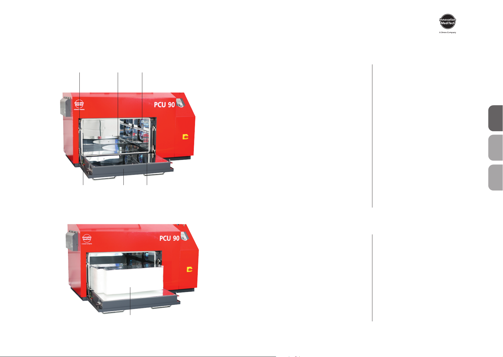
PCU 90
8
5 Sicherheitshinweise
1. Das Gerät darf nur entsprechend
der vorliegenden Bedienungsanleitung
verwendet werden. Wir übernehmen
keine Haftung für Schäden, die durch
unsachgemäßen Gebrauch bzw. feh-
lerhafte Bedienung entstehen.
2. Die angegebene Spannung auf dem
Typenschild muss mit der Spannung
der Stromquelle übereinstimmen.
3. Das Gerät nur an einer Steckdose mit
Schutzleiter betreiben. Den Netzstecker
niemals mit feuchten Händen anfassen.
4. Das Gerät muss auf einem stand-
festen und ebenen Untergrund ste-
hen, der für das etwa 140 kg schwere
Betriebsgewicht ausreichend stabil und
belastbar ist.
5. Keine Gegenstände außerhalb der
Polymerisationskammer in das Gerät
einführen.
6. Es dürfen nur Zubehör und Ersatz-
teile verwendet werden, die vom Her-
steller freigegeben sind. Für Schäden,
die durch den Einsatz fremder Teile ent-
stehen, übernehmen wir keine Haftung.
7. Die Bedienungs- und Sicherheits-
elemente des Gerätes nicht arretieren.
8. Das Gerät ist vor jedem Betrieb auf
ordnungsgemäßen Zustand und Be-
triebssicherheit zu überprüfen. Falls der
Zustand nicht einwandfrei ist, darf das
Gerät nicht benutzt werden und muss
entsprechend gekennzeichnet werden.
9. Vor der Reinigung und der Wartung
des Gerätes oder dem Auswechseln
von Teilen, ist unbedingt der Netzste-
cker zu ziehen.
10. Schilder und Aufkleber müssen stets
in gut lesbarem Zustand gehalten wer-
den und dürfen nicht entfernt werden.
11. Das Öffnen des Gerätes und Instand-
setzungen dürfen nur von zugelas-
senen Fachkräften durchgeführt wer-
den.
12. Als Schutzgas nur Stickstoff oder
Kohlendioxid verwenden. Keinesfalls
brennbare oder giftige Gase verwen-
den. Beachten Sie die allgemeinen
Sicherheits- und Unfallverhütungs-
vorschriften für den Umgang mit dem
gewählten Gas.
13. Nur zugelassene Gasdruck-Fla-
schen verwenden.
14. Bei Anschließen der Gasdruck-Fla-
sche mit dem Gerät überprüfen Sie die
Achtung! Lesen Sie diese Hinweise vor dem Anschließen und der Inbetriebnahme
des Gerätes sorgfältig durch. Die Betriebssicherheit und die Funktion des Gerätes
können nur dann gewährleistet werden, wenn sowohl die allgemeinen Sicherheits-
und Unfallverhütungsvorschriften des Gesetzgebers als auch die Sicherheitshinweise
in der Bedienungsanleitung beachtet werden.
Dichtigkeit des Zuführungsschlauches.
Stellen Sie sicher, dass die Gasdruck-
Flasche nicht umkippen kann.
15. Verbinden Sie nie die Gasflasche,
ohne einen Druckminderer zu verwen-
den, das Gerät darf mit einem maxima-
len Druck von 5 bar (70 psi) bedient
werden.
16. Wenn das Gerät nicht verwendet
wird, schließen Sie die Gasversorgung.
Betreiben Sie das Gerät nicht unbeauf-
sichtigt.
17. Sorgen Sie für eine ausreichende
Belüftung im Arbeitsbereich.
18. Der Druck der Gasleitung darf 5 bar
(70 psi) nicht überschreiten.
19. Bewahren Sie keine leichtentzünd
-
lichen Stoffe in unmittelbarer Umge-
bung des Gerätes auf.
20. Zugelassene Bediener: Der Betrei-
ber des Gerätes muss dem Bediener die
Betriebsanleitung zugänglich machen
und sich vergewissern, dass er sie
gelesen und verstanden hat. Erst dann
darf der Bediener das Gerät in Betrieb
nehmen.
21. Um Eindringen von Wasser in das
Gerät (z. B. Spritzwasser) zu vermeiden,
sollte das Gerät in trockener Umge-
bung aufgestellt werden.
22. Das Gerät ist bei Nichtbenutzung
vom Netz zu trennen.
23. Die Schublade nur am Griff anfassen,
um Quetschungen zu vermeiden.
24. Das Gerät nicht betreiben, wenn
die Montageklappe an der Rückseite
des Gerätes geöffnet ist.
25. Eigenmächtige Umbauten und Ver-
änderungen sind aus Sicherheitsgrün-
den unzulässig.
26. Die vorgeschriebenen Betriebs-
und Wartungsbedingungen dieser
Gebrauchsanleitung sind zwingend
einzuhalten. Beim Arbeiten mit der
PCU 90 sind die allgemeinen Unfall-
verhütungsvorschriften zu beachten.
27. Nicht auf die Glasplatte fassen, da
diese im Betrieb sehr heiß wird.
28. Den Lüftungsschlitz auf der linken
Seite des Gerätes nicht verstopfen
oder blockieren, immer ausreichend
Abstand zur Wand lassen.