Drieaz DRIFORCE F219 User manual

OWNER’S MANUAL
SAFETY • OPERATING INSTRUCTIONS
MAINTENANCE • SPECIFICATIONS
DRIFORCE
InterAir Drying System
Model F219
PURCHASE DATE: ____________________________ SERIAL NO: __________________________________
DISTRIBUTOR: _____________________________________________________________________________
THIS MANUAL CONTAINS IMPORTANT SAFETY WARNINGS.
PLEASE READ THESE AND SAVE THESE INSTRUCTIONS FOR FUTURE REFERENCE.
DRI-EAZ PRODUCTS, INC. • 15180 Josh Wilson Road, Burlington, WA 98233 • 800-932-3030
www.dri-eaz.com
07-00274D 2009-01 1Copyright 1999, Dri-Eaz Products, Inc.

07-00274D 2009-01 2Copyright 1999, Dri-Eaz Products, Inc.
TABLE OF CONTENTS
INTRODUCTION ..................................................................2
SAFETY................................................................................ 2
PRINCIPLES OF DRYING ................................................... 3
OPERATING INSTRUCTIONS............................................. 4
Tools..............................................................................4
Wall Preparation ............................................................ 4
Making Holes................................................................. 4
Steel Studs ....................................................................4
Odor and Mold ..............................................................4
DriForce Blower Setup ..................................................4
Laying Out Manifolds..................................................... 5
Laying Out Supply Tubes .............................................. 5
Standard Drying Procedure ........................................... 6
Extraction Drying ...........................................................6
Drying Ceilings and Cabinets ........................................ 6
Supplying Extra-Dry Air ................................................. 6
Operating Instructions Summary ................................... 7
MAINTENANCE.................................................................... 7
SPECIFICATIONS................................................................ 8
INTRODUCTION
The DriForce is an equipment system used in wa-
ter damage restoration and restorative drying work. It
is specifically designed for structural cavities like
those between studs in walls, between joists in floors
and ceilings, under and behind cabinets and other
built-ins, above door and window headers, and many
other areas that are difficult to access.
The system works because airflow across wet ma-
terials is a basic principle of drying. The DriForce
will dry materials in either the injection mode (push-
ing dry air into wall cavities) or in the extraction
mode (vacuuming moist air out of wall cavities) to
maximize both drying speed and environmental con-
siderations.
The DriForce blower has a stainless steel base and
a double-wall polyethylene housing. It is connected
to an Air Delivery System (ADS) made of flexible,
crushproof polyethylene hose which is high-
temperature resistant and caution-colored for visibil-
ity. The ADS is ended at any manifold by plugging it
with a supplied end cap. The ADS attaches to mani-
folds with convenient slip-on hose cuffs. Up to 12
supply tubes are connected to each manifold, and
lead to air nozzles that complete the air-delivery sys-
tem.
The injection-molded plastic air nozzles have a
tapered design to improve air delivery and create a
tight seal. Fins on each side of the air nozzle allow
locking in place with a quarter turn, which is espe-
cially important when drying ceilings.
Three advantages of the DriForce are minimal
damage, high coverage, and great versatility. The air
nozzles create minimal damage because they need
only small holes for installation, less than ¼", making
them easy to hide or repair. The system is high-
coverage, providing everything you need to treat over
90 feet of 2 × 4 constructed wall. It is versatile be-
cause it can dry many combinations of walls, cabi-
nets, ceilings, headers, etc., in either the injection or
extraction mode.
While supplying the high volume and high pres-
sure of air this technology demands, the DriForce
uses less than 3 amps of standard 115-volt power.
The blower unit itself weighs 14.5 pounds, about half
the weight of a TurboDryer.
SAFETY
SAVE THESE WARNINGS
Dri-Eaz is concerned about the safety of everyone
who uses or comes in contact with the DriForce. The
DriForce is designed to be operated in compliance
with the safety warnings and instructions provided in
this manual.
Like other electrical devices, the DriForce can be-
come dangerous if abused, damaged or misused.
Failure to observe the following warnings can result
in injury to persons, fire damage, or damage to the
DriForce. To reduce the risk of electrical shock, fire,
or personal injury, read and follow each of the warn-
ings below before using the DriForce.
DANGER
Removal or alteration of the grounding plug, or use of
an adapter that defeats the DriForce’s electrical
grounding, can create risk of serious personal injury
or fire in the event of damage to or malfunction of this
product. Do not use the DriForce for any reason if it
cannot be properly grounded. If you are unsure
whether a receptacle is grounded, test the outlet with
a receptacle tester or consult an electrician.
Keep a Neat and Clean Installation. Locate the
ADS out of heavy traffic areas. This not only gives a
professional appearance, it also reduces any possible
hazard of tripping accidents or becoming entangled
with the installation.
Do Not Use to Extract Water. The DriForce is
used to move air, not water. Do not use the DriForce
as a vacuum for extraction of water or debris.
Keep the Blower Grounded: Always operate the
DriForce with the three pronged grounding plug and
a grounded electrical outlet. Never remove this three-
pronged plug. Do not use an ungrounded extension
cord or an ungrounded adapter. The grounding prong
on the plug is an essential safety feature that helps

07-00274D 2009-01 3Copyright 1999, Dri-Eaz Products, Inc.
reduce the risk of shock or fire in the event of an
electrical hazard.
Extension Cords: Extension cords must be
grounded and be able to deliver the appropriate volt-
age to the DriForce. An extension cord up to 25 feet
in length must have 16 AWG wire or heavier. An
extension cord up to 50 feet in length must have 14
AWG wire or heavier.
Protect the Power Cord From Damage: Never
operate the DriForce with cut, nicked, abraded,
frayed or otherwise damaged power cords or exten-
sion cords as this may lead to electrical or fire haz-
ards. Never unplug the DriForce by pulling on the
cord. Grasp the plug firmly and pull straight out.
Take precautions not to use the cord in a way where
damage may occur. Keep cords away from heated
surfaces. Inspect cords before each use and replace
cords that show signs of damage.
WARNING
To reduce the risk of fire or electric shock, do not use
a DriForce with a solid-state speed control device.
Keep Motor Dry: Never allow water inside the
DriForce motor. If the motor becomes wet for any
reason, thoroughly dry it before use.
Keep Children Away: Do not allow children to
play with or around the DriForce. Be sure the Dri-
Force is inaccessible to children when unattended.
Children can hurt themselves by playing with or
around the DriForce. Secure all areas in which the
unit is left unattended while running.
Handle With Care: Do not drop or throw the
DriForce for any reason. Rough treatment can dam-
age the motor or wiring, creating a hazardous condi-
tion.
Run on Stable Surface: Always operate the Dri-
Force on a stable flat surface such as the floor. Do
not operate the unit from places where it can fall or
be pulled down causing injury. Beware that the unit
may vibrate or be pulled from smooth surfaces such
as counter tops and cause an injury, fire or electrical
hazard.
Air Intakes Must Be Clear: Operate the Dri-
Force away from draperies and other materials that
may come in contact with the air intakes. Do not al-
low any material to clog or block air intakes, as this
may cause the unit to overheat and result in a fire or
electrical hazard.
Keep Foreign Matter Out: Do not allow oil,
grease, solvents or other matter (including sawdust
and drywall dust) to be drawn into the air intake of
the DriForce. Never direct fogged or liquid chemicals
of any kind into the air intakes of the unit.
CAUTION
Never operate the DriForce in pooled or standing wa-
ter, as this may create a risk of serious injury from
electrical shock.
Keep Away From Heaters: Do not use the unit
for circulating hot air. Avoid placing the unit to a
source of warm air. The housing could melt or the
motor could overheat and cause a fire or electrical
hazard.
Don’t Modify Unit: Never modify the motor,
wiring or casing of the DriForce for any reason.
Modifications to the unit can lead to fire or electrical
hazards.
Share Owners Manual: Be sure to include a
copy of the DriForce Owners Manual whenever you
loan, rent, or otherwise allow someone else to use
your DriForce. They need the same safety informa-
tion that you require for safe efficient operation.
Make sure that all technicians and operators have
read and understand the manual.
Maintenance or Repair: Do not attempt to disas-
semble or repair the DriForce if you are not qualified
to do so. If the DriForce is not working as it should,
return it to Dri-Eaz or an authorized dealer or dis-
tributor for servicing. Note: For information about
authorized repair and maintenance call Dri-Eaz Prod-
ucts at 800-932-3030.
DANGER
Do not attempt to service or clean the DriForce while
it is plugged into an electrical outlet or while the
blower is operating as this may lead to risk of electri-
cal shock or injury. It is dangerous for an unqualified
individual to attempt to disassemble or repair the Dri-
Force.
PRINCIPLES OF DRYING
Moisture trapped in and behind building materials
can result in extensive damage and can raise health
and safety concerns associated with mold and mil-
dew.
Whether excessive moisture is present or not, and
where it is located, is best determined using profes-
sional moisture detection equipment such as penetrat-
ing and non-penetrating moisture meters, and thermo-
hygrometers that measure the amount of moisture
present in the air as water vapor. The use of marks or
colored stick-on paper tabs can help monitor the job.
Keeping moisture and humidity records can provide
an accurate job history for your firm and for the cus-
tomer.

07-00274D 2009-01 4Copyright 1999, Dri-Eaz Products, Inc.
Successfully drying a structure requires the re-
moval of excessive moisture. One basic principle is
that airflow speeds up the rate of evaporation. Creat-
ing air movement in any problem areas will tend to
support evaporation and reduce the potential for
problems. A second principle of drying is to dehu-
midify the air in the area being dried. A third is to
add heat, as practical.
The DriForce employs all three of these drying
principles. Air is pushed or pulled through air noz-
zles, either into or out of structural cavities. In both
cases, air movement in the cavities speeds up the dry-
ing process. Dehumidification can be improved,
when forcing air into cavities, by making sure that
the air entering the DriForce is as dry as possible,
usually by using a low grain refrigerant or desiccant
dehumidifier. Finally, heat generated by the DriForce
blower motor enters the airflow through the ADS,
increasing the temperature of the air it provides for
drying.
OPERATING INSTRUCTIONS
Tools
Tools you will need are: pencil, tape measure, ra-
zor knife, drywall taping knife, small pry bar, nail
puller, screw driver, a carpet awl for creating holes,
and sometimes a drill with a 3⁄16" bit.
Wall Preparation
In most cases of wet walls, remove baseboard or
cove base. First, use a razor knife to score along the
top of the base where it meets the wall, to reduce
damage to the painted surfaces and make a profes-
sional re-installation easier. When prying base away
from the wall, protect the wall surface by inserting a
drywall knife between the pry bar and the wall. Pull
remaining nails out of the wall, or through the back
of the baseboard. Write a number on the wall and the
corresponding base so you will know where to reap-
ply it.
The DriForce will deliver air to structural cavities in walls,
ceilings, under and above cabinets, and many other areas.
Starting 8 inches from an inside or outside corner
of the wall, make a mark. This should be at about the
center of a stud cavity. Now move the tape to that
mark, and mark the wall every 16 inches. An elec-
tronic Stud Finder is a very helpful tool when doing
this, and is available at most hardware and home cen-
ters. The goal is to provide at least one hole between
each set of studs.
Making Holes
Now make holes for air nozzles at each mark,
usually just over the wall plate, which is a 2 × 4 laid
flat on a wood or concrete subfloor. These holes
should be approximately 2 inches above the floor, but
below the line indicating the top of the baseboard.
The easiest way is to punch holes with a carpet awl.
You can also use a drill with a 3⁄16" bit. A larger hole
would be more time-consuming to patch, and would
somewhat decrease efficiency by leaking air.
In cases of where rubber cove base or elaborate
baseboards are used, it may be best to drill above
them, and carefully patch the small holes later.
When making holes into cavities in cabinets,
headers, and ceilings, think ahead about reducing
your repair later on. For example, when drying be-
hind rubber wainscoting or cove base, you may be
able to peel down the covering 16 inches, just enough
to insert the air nozzle. The small area were peeled
can be re-glued, saving complete replacement of the
molding.
Steel Studs
Steel studs are common in commercial buildings.
They are set in a channel that can hold large volumes
of water. To access these areas, drill holes approxi-
mately ½ inch from the floor at a downward angle.
Extract standing water with your extraction equip-
ment before attempting to dry. Do NOT use the Dri-
Force to try to extract standing water of any kind.
CAUTION
Do not use the DriForce to extract debris or standing
water of any kind.
Odor and Mold Control
If you suspect that mold and mildew may be
growing inside cavities, follow the appropriate indus-
try mold remediation safety standards.
DriForce Blower Setup
Set the DriForce blower in any convenient loca-
tion, but out of traffic areas as much as possible, to
minimize a trip-and-fall hazard from the blower and
the ADS.

07-00274D 2009-01 5Copyright 1999, Dri-Eaz Products, Inc.
Use the muffler-filter when the DriForce in the air
injection mode. This will reduce blower noise sub-
stantially, and also filter out large particles from be-
ing sucked through the blower. Place the muffler-
filter on the air intake connector, and place the ADS
on the air outlet connector.
When using the DriForce in the air extraction
mode, it is recommended not to use the muffler-filter,
but to use a HEPA Filter accessory. See “Extraction
Drying,” p. 6.
For maximum efficiency, run a short length of
ADS to a T-fitting, and then approximately equal
lengths of ADS in opposite directions to wet areas
being treated. Two shorter lengths of ADS running
from each side of a T-fitting give better airflow than
one long installation in a line.
Use a hose clamp on the outlet fitting of the Dri-
Force, and another where the first ADS meets the
first manifold.
Use at least two manifolds in the air injection
mode for greatest efficiency. Notice the ventilation
ports on the bottom of the stainless steel base of the
DriForce blower. Covering up or clogging these ven-
tilation ports can cause the blower to run at a higher
temperature which will shorten its life. Keep loose
rags, fabrics, dirt, or other debris from covering or
clogging the ventilation ports.
Laying Out Manifolds
Next, determine the number of manifolds needed
for the job. The following procedure will give 25 to
30 air exchanges per hour in each cavity, which is
effective for most situations. Use a formula of one
manifold (12 air nozzles) for each 14 feet of interior
or 2 × 4 framed wall. For 2 × 6 exterior framed walls,
common walls in apartments and condos, double-
sheeted fire walls, and dense or water-resistant cov-
ered walls, use a formula of one manifold (12 air
nozzles) for each 7 feet of wall. Wainscoted, tile-
covered, or multiple-thickness walls may benefit
from using twice the number of air nozzles.
After determining the number and distance of
manifolds, set up the ADS system. Pre-assembling
the manifolds, tubing and air nozzles will save con-
siderable setup time.
Diagram shows two inline ADS lines (left), and two double-ADS
lines running from a T-fitting. It also shows tubing layouts for one
or two air nozzles into each wall cavity.
ADS runs from the DriForce blower and attaches with a standard
hose cuff to a manifold. Supply tubes run from the manifold to air
nozzles that are inserted into a wall or other structural cavity. If possible, direct air from the blower through a
short section of ADS to the T-fittings, then run the
ADS from both sides of the T. This will enhance per-
formance by balancing the airflow. You can also use
the T-fittings to dry in several rooms at once.
Laying Out Supply Tubes
Supply tube layouts will vary according to the job,
especially when running air nozzles above wainscots
or cabinets, into ceilings, etc.
The most versatile setup for most standard wall-
drying jobs is as follows:
1. Set up THREE manifolds with the following
lengths of tubing:
Quantity Length Locations on Manifolds
4 4 feet Outlets 1, 2, 11 and 12
4 3.5 feet Outlets 3, 4, 9 and 10
4 1 foot Outlets 5, 6, 7 and 8

07-00274D 2009-01 6Copyright 1999, Dri-Eaz Products, Inc.
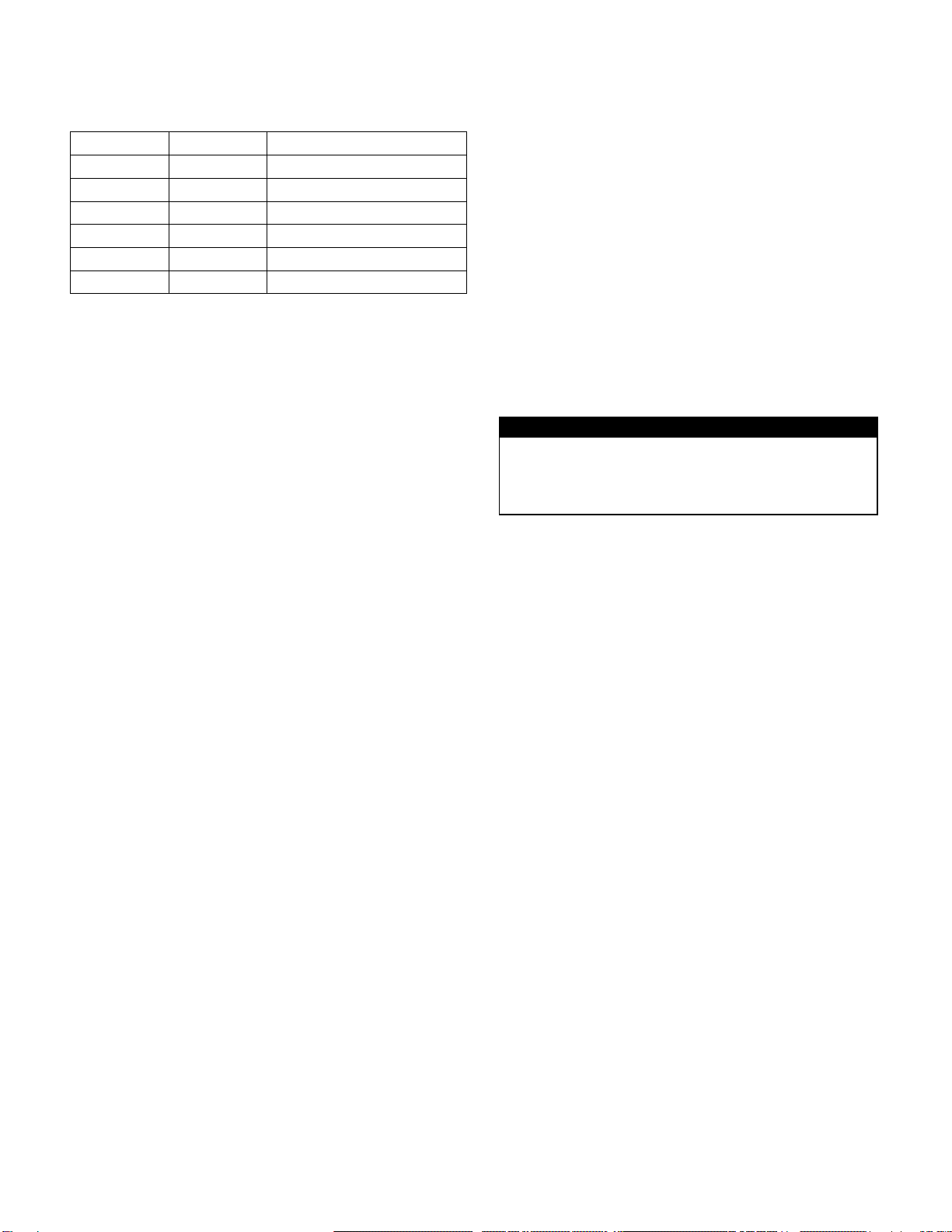
2. Set up the remaining FIVE manifolds with the fol-
lowing lengths of tubing:
Quantity Length Locations on Manifolds
2 7.5 feet Outlets 1 and 12
2 6.5 feet Outlets 2 and 11
2 5.5 feet Outlets 3 and 10
2 4.5 feet Outlets 4 and 9
2 2.5 feet Outlets 5 and 8
2 1 foot Outlets 6 and 7
To each outlet on a manifold, attach a length of
supply tubing, and insert an air nozzle in the other
end of the tubing.
Seal off the last manifold on each run of ADS
with a supplied endcap plug. Now place the air noz-
zles into the holes you have drilled or punched.
Although not necessary in most cases, it is some-
times helpful to awl-punch or drill a small vent hole
placed just above the highest moisture point on the
wall. This vent hole can speed up the drying process
by supplying more dry air to affected materials. The
small size of the hole often allows you to patch it
with little difficulty.
Standard Drying Procedure
Now you are ready to dry. Make sure you have
undamaged electrical cords, plugs, extension cords if
used, and circuits with 3 amps of available power.
Turn on the power switch, and ensure that all the
ADS, T-fittings, hose cuffs, manifolds, supply lines,
and air nozzles are properly installed with minimum
air leakage.
Attach the ADS to the vacuum side of the Dri-
Force blower unit. For the first portion of the job, it is
recommended to use the system in the vacuum or
extraction mode to remove the bulk of the humidity
laden air from structural cavities (see “Extraction
Drying,” below.) Run in the vacuum mode until the
specific humidity in the affected area of the job reads
the same or lower as the specific humidity in an unaf-
fected area of the job.
After the humidity in the affected area of the job
is the same or lower as that in an unaffected area,
move the ADS from the vacuum to the pressure out-
let of the DriForce and install the muffler-filter. You
will now be forcing air at high pressure into the struc-
tural cavity, to finish the drying process.
Extraction Drying
As explained above, drying by vacuuming air
from structural cavities, setting up the DriForce in the
extraction mode can speed drying times. Also, using
the extraction mode ensures that moist and possibly
contaminated air does not get forced into previous
dry and unaffected areas.
When using the DriForce in the vacuum or extrac-
tion mode, do not exhaust the air into an occupied
structure. Use vacuum hose to exhaust the air to the
outdoors, completely outside the structure. This will
ensure that contaminants (including moisture, mold
spores, mold mycotoxins and byproducts) are not
transferred from within structural cavities into an oc-
cupied area. Contaminants may create health con-
cerns such as allergic reactions and illness.
Do not use the muffler-filter that is supplied with
the DriForce in the vacuum or extraction mode. This
filter is not a HEPA-grade filter, and will not meet
the requirement to ensure that possible contaminants
are not exhausted into an occupied area. Use the muf-
fler-filter only in the injection or blowing mode.
CAUTION
When using the DriForce in the vacuum or extraction
mode, exhaust the air to the outdoors or use a HEPA
filter attachment, to ensure that possible contami-
nants are not exhausted into an occupied area.
Drying Ceilings and Cabinets
Drying ceilings is accomplished in much the same
manner as walls, and can be done at the same time as
wall drying. Remember that ceiling joists are usually
a minimum of 2 × 6. Larger lumber and larger struc-
tural cavities will require more air nozzles.
Drying under and behind cabinets is often a chal-
lenge, as it is difficult to measure trapped moisture,
and also difficult to access the areas with tubing and
air nozzles. If your moisture measurements are un-
sure, it is better to assume that materials are wet.
Wherever water flowed, make sure you provide flow-
ing dry air. When necessary, remove, dry, and reset
cabinets.
Supplying Extra-Dry Air
To increase drying speed when forcing air into
cavities, ensure that that air going into the DriForce
blower is as dry as possible. One way is to position
the output airflow from a dehumidifier near the Dri-
Force air inlet.
Even better is to attach ducting to the air output
from the dehumidifier and lay it near the DriForce.
Attach a short piece of ADS to the air inlet of the
DriForce, and slip the other end a foot or two up into
the ducting from the dehumidifier. Do NOT tape up
or completely seal such ducting. This could unbal-
ance the airflow through the dehumidifier and possi-
bly damage the dehumidifier.
Super-dry air from a desiccant dehumidifier can
be especially helpful to speed up a drying job, or to
dry difficult materials like lath and plaster, double-

07-00274D 2009-01 7Copyright 1999, Dri-Eaz Products, Inc.
sheeted or fire walls, insulated walls, and walls cov-
ered with vinyl wallpaper or impermeable paint.
After drying is complete, you must fill any holes
you have created. Remember that your local fire code
applies to outside walls and firewalls, and you must
repair up to code. Special fireproof caulks and tapes
are available that can be helpful.
Operating Instructions Summary
The DriForce will help restore building materials
in walls, ceilings, headers, cabinets, and other struc-
tural cavities to their pre-loss condition. The high-
pressure air it delivers helps to rapidly remove mois-
ture that was trapped in the cavity. The DriForce will
dry several difficult areas at once, such as cavities
below and behind cabinets and in the ceilings above
these same cabinets or walls. The versatility of the
DriForce InterAir Drying System, combined with
TurboVents and Mini-TurboVents, TurboDryers, and
DrizAir dehumidifiers, will create a highly effective
drying system.
The DriForce InterAir Drying System from Dri-
Eaz Products is versatile and easy to use. It will pro-
vide you with years of service, removing moisture
from difficult-to-access areas on job after job. The
DriForce will help you provide a superior restoration
service to your customers by returning the property to
pre-loss conditions faster, and saving the building
owner or insurance company unnecessary reconstruc-
tion costs.
DANGER
Do not attempt to service or clean the DriForce while it is
plugged into an electrical outlet or while the blower is oper-
ating as this may lead to risk of electrical shock or injury. It
is dangerous for an unqualified individual to attempt to dis-
assemble or repair the DriForce.
MAINTENANCE
Proper maintenance will keep your DriForce In-
terAir Drying System in good condition for years to
come.
Check both the inlet and outlet of the DriForce
unit for obstructions or debris after each use.
Inspect the muffler filter, and clean as needed by
vacuuming or washing. You can further clean the
filter by washing with Dri-Eaz brand Milgo-SR, at
dilution rates shown on their labels.
Check manifolds, tubing, air nozzles and other
ADS components, and replace if needed.
Shine the DriForce housing and other components
with a vinyl cleaner and protectant such as Mi-
croGuard Equipment Cleaner and MicroGuard
Equipment Protectant, available from your Dri-Eaz
distributor.
Service parts, plus other maintenance and war-
ranty information, are available from the Dri-Eaz
Service Department. Call 800-932-3030, or fax
360-757-9536.
SPECIFICATIONS
Model DriForce InterAir Drying System, F219
Dimensions (H × L × D) 14 × 14 × 12 in. 35 × 35 × 30 cm
Total system airflow
(maximum)
100 CFM (cubic feet per minute)
6,000 cubic feet per hour
2.3 m³/min.
170 m³/hour
Working static pressure 38 in. (water lift) 97 cm (water lift)
Weight (DriForce base unit only) 14.5 lbs. 6.3 kg
Air nozzle hole size Less than ¼ in. Less than 6 mm
ADS (Air Delivery System) 13 sections, 7 ft. each (91 ft. total)
1.5-inch “magnum” crush-proof
13 sections, 2 m each (28 m total)
3.8 cm “magnum” crush-proof
Flexible tubing 400 feet of ⅜" ID 122 meters of 0.375 mm ID
Power draw
(115 volts)
4.8 amps (maximum)
3.0 amps (average use)
Carrying/storage system 2 “suitcase” duffle bags with handle and wheels
Drying modes Either positive or negative pressure
Parts 100 air nozzles, 8 manifolds (12 outlets each), 4 manifold endcaps, 4 coupler fittings,
2 hose clamps, 2 T-fittings, 13 hose assemblies with cuffs, 25 tube extender connec-
tions, 1 muffler
Safety listings UL, C-UL
Table of contents
Other Drieaz Cleaning Equipment manuals