ELSEC 764 User manual

764 ENVIRONMENTALMONITOR
USERMANUAL
LITTLEMORE SCIENTIFIC ENGINEERING (ELSEC)
GutchpoolFarm
Gillingham
Dorset
UK
Tel: (+44) (0)1747 835550
Fax:(+44) (0)1747 835552
Email:elsec@elsec.co.uk
764.DOCV3.702


CONTENTS
INTRODUCTION...............................................................................................1
BASIC OPERATION .........................................................................................2
Set Button......................................................................................................3
UNITS OF MEASUREMENT.............................................................................4
Ultra-Violet (UV)............................................................................................4
Visible Light...................................................................................................5
Temperature..................................................................................................6
Humidity ........................................................................................................6
MAXIMUM AND MINIMUM...............................................................................7
DISPLAY...........................................................................................................8
Contrast.........................................................................................................8
Backlight........................................................................................................8
DATA LOGGING...............................................................................................9
Wrap Data.....................................................................................................9
ShowStatus..................................................................................................9
Start Logging.................................................................................................9
Stop Logging...............................................................................................10
Re-Starting logging......................................................................................10
Logger-PC Communications.......................................................................10
Installing the Software.................................................................................13
Viewing the Results using RView................................................................14
CLOCK............................................................................................................15
Setting the Time..........................................................................................15
Setting the Date...........................................................................................15
Date Format................................................................................................15
Hiding the Clock..........................................................................................15
MAINTENANCE..............................................................................................16
Battery.........................................................................................................16
Mains Power Supply....................................................................................16
Software Version.........................................................................................16
CALIBRATION................................................................................................17
Humidity ......................................................................................................17
The CalibrationKit...................................................................................17
Temperature................................................................................................19
UV & Visible Light........................................................................................20
SERVICE AND SUPPORT..............................................................................21
SPECIFICATIONS..........................................................................................22
PRINTED 31-Aug-07

1
INTRODUCTION
One of the primary responsibilities of the custodian of artworksandmuseumartefacts
is to preservethemfor future generations.How they are stored and displayed is
central to this,the 764Environmental Monitor is an easyto use toolto helpin
achievingthe safest longtermprotection.
For many years it has been recognised that one of the major causes of damageto
museumobjects and other antiquities is the fadingand rottingeffect of light on the
object. The most damagingpart of the illumination is its ultraviolet (UV) content.
Usingthe 764 measurements can be takenof the proportion of UV present as
microwatts perlumen (mW/lumen),thetotal amountof UVas milliwattsper square
meter (mW/M2)and the amount of visible lightpresent (Lux).
Most objects arealso sensitive to humidity and temperature.The 764also measures
humidity as %relativehumidity and temperature as °Cor °F.
The 764 canbe left for extendedperiods tolog the aboveparameters at auserset
interval (10 seconds to 1hour).The saved datacan then be transferred to acomputer
for display, graphingetc.
We always want to improve our products.Ifyou haveany suggestions please send
themto us.

2
BASICOPERATION
To take areadingthe appropriateyellowbutton is pusheddependingonthe
measurement required and the readingis taken.
UV=Ultra Violet (µW/lumen or mW/M2)
Vis=Visible light (Lux or Foot-candles)
T=Temperature (Centigrade or Fahrenheit)
RH=Humidity (%RelativeHumidity)
The unit automaticallyturns off 10 seconds after the button is released unless abutton
is held down for over 5seconds, this will causereadingsto be taken continuously until
abutton is pressed.
Ifthe TandUV buttons arepressed together then all parametersare displayed atthe
sametime. Hold both the buttons down for over 5seconds for acontinuous readout.
Note that the buttons should be pressedfirmlyfor asecond or so to ensure reliable
operation.
Typical display:
A
B
C
D
E
Lux
1234
Min: 1.2 21-08:14
Max: 3456 14-09:34
B H L 3/11/06 10:20
A:Units of measurement
B: Current reading
C: Minimumreadingsince last reset, day ofmonthand timeof minimum
D: Maximumreadingsince last reset, day of month and timeof maximum
E: Hshows that the readingis “held” and the unit will turn itself off after10 seconds
of inactivity. Around blob shows the unit is in continuous readingmode until a
button is pushed, nothinghere means that asingle readingis beingtaken.
The Lindicates loggingis in operation, Wis shown if logged data is wrapped.
The current timeand date are also shown. Unless they are hidden by pressing
Set\Clock\Hide-Unhide.
Ifabattery symbol appears at Bit means that the batteries need to be replaced.
Min &Max are reset by pressingSet\Max-Min\Reset (Press Set 3times)

3
The aboveformat is slightly different forsome parameters and can be altered by the
user if required, see below.
Set Button
The blue Set button is used to access advanced functions,changeunits etc.Ifit is
pushed once amenu similar to that below is shown:
Max-Min>
Display>
Units>
Clock>
Calibrate>
The first menu item“Max-Min” ishighlighted,different menu itemscanbe
highlighted usingthe éand êbuttons.Thewanted action is done by highlightingthe
appropriate menuitemand pressingthe Set button.To abortwithoutdoinganything
press the Xbutton. Insomecases afurther sub-menu is displayed with more choices.
Elsewhere in this manual directions in the formSet\item1\item2are given. This means
Press Set, select item1in the first menu, pressSet again, select item2in the next menu
and press Set.
To takeameasurement without havingto lookat the display while the readingis
taken(for example wherethe operators headmay effectthe reading)proceed as
follows:
1.Position the monitor where the readingis to be taken.
2.Push the appropriate button for 1-2 seconds andrelease.
3.Hold the monitor in position for at least 2seconds.
1. Without operatingany buttonsby mistake movethemonitorso the reading
can be noted before it turns itselfoff.

4
UNITS OFMEASUREMENT
Ultra-Violet (UV)
Traditionally UV has been measured in museumsas the proportion of ultraviolet
present.This result is useful for checkingaparticular lamp or window because the
proportion of UV does not changewith the distance fromthe light source.Usinga
simple rule the amount of UV on an object can be limited.Itis usual to arrangethat
the proportionof UVshould notexceed75µW/lumen inmuseumsand galleries,
thoughsomeorganisations try to keep UV levels below 25µW/lumen
The damageis done by the total amount of UVfallingon the object so it is useful to
be able to measure thisdirectly, especiallyif non standard amounts of illuminationare
required.The amount of UV should be aslittle as possible but in general should not
exceed 20mW/M2, againsomeorganisations keep the level below 6mW/M2.
Both the aboveunits are displayed when theUV button is pressed,one in large
characters, the other smaller at the bottomof the screen. Which is displayed where can
be swapped by pressingSet\Units\µW/Lumn-mW/M².

5
VisibleLight
This can be displayed either in Lux or Foot-candles.To changethe units press
Set\Units\Lux-Footcandl.
Avisible lightreadoutis providedto control illumination andlimit damagedoneby
visible light. Normal museumlight levelsshould be limited to 150-250 Lux.
Once measurements have been made the light level can be altered if necessary and UV
filters can be fitted on windows, fluorescent tubes or other UV producinglight sources
as required. These filters often deteriorate overaperiod of years so it is essential to re-
checkthemperiodically.
Magazinereprintson the subjectof museumlighting,UVetc canbe obtained from
the manufacturer.
Suggested light levels for various other purposes are given below:
Corridor, stairs etc 100/150 Lux
Warehouses, storagebays 100/150 Lux
General office work 300/500 Lux
Roughbench/machine work 300/500 Lux
Mediumbench/machine work 500/700 Lux
Drawingoffices 750/1000 lux
Fine bench work 1000/1500 Lux
Fine inspection 1500/3000 Lux
Minute work 3000/5000 Lux

6
Temperature
Temperature can bemeasured indegrees Centigradeor Fahrenheit.To changethe
units press Set\Units\°C-°F.
Humidity
Humidity is measured as %relativehumidity (%RH).This is the fraction of the
maximumamount of water that the air canhold at the current temperature and
pressure.
Ingeneral if the temperatureis reduced the amount of waterit can hold getsless.Soif
the temperature of someair is reduced its humidity rises, and at somepoint the air will
not be able to hold the water it has and water will start to condense out (form
mist/cloud or drops of water on asurface),therelativehumidityhas reached 100%.
The temperature at which this happens is the dewpoint. The 764 displays the dewpoint
with the humidity and with the temperature.
The temperature/dewpointdifference isoften used as ameasure ofthe likelihoodof
condensation (fog)occurring,particularly inmeteorology.Ifthetemperature is only
one or two degrees abovethe dewpoint in the eveningthen fogis likely as the
temperature falls duringthe night.
The UK National Trust tries to keep the indoor relativehumiditybetween 50% and
65%, aimingfor 58%.

7
MAXIMUMAND MINIMUM
The maximumand minimumvalues for each unit are displayed alongwith the day of
the month and timethe maximumor minimumoccurred.
The values can be reset by pressingSet\Max-Min\Reset (This equates to pressingSet
3times).
To find the date when maxima&minima occurred press Set\Max-Min\Date or Time,
repeat to display the times again.
The maximumand minimumvalues are also set when data loggingis active.
8
DISPLAY
Contrast
The display contrast can be increased/decreased by pressingSet\Display\ContrastUP
or DOWN. Ifthis is done the menu continues tobe displayed and the set button can be
pressed repeatedly until the required contrast is achieved.
Backlight
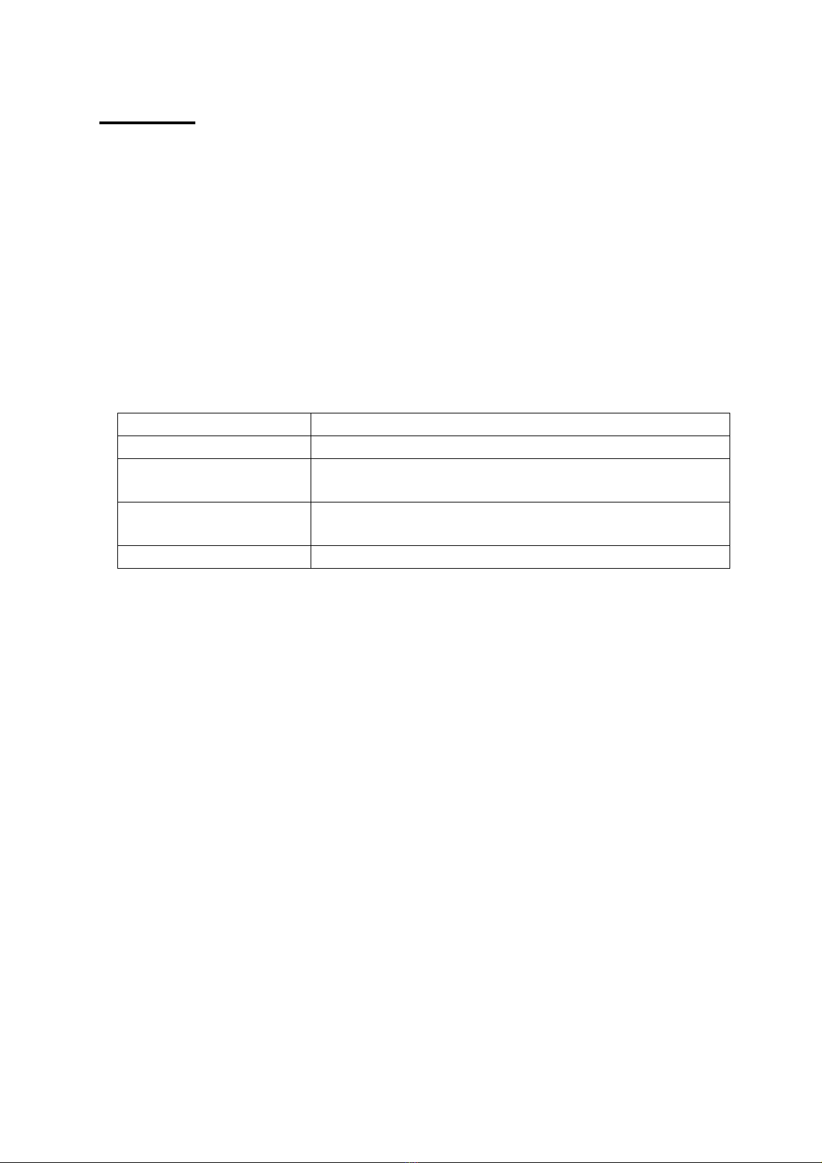
The display backlight operation can be adjusted fromthe Set\Display menu as
follows:
Menuitem Action
Lampoff Backlight always off
Lampmostly off Backlight initially off,turnson if visible light is less
than 10 Lux
Lampmostly on Backlight is initially on, turns offif visiblelight is more
than 10 Lux
Lampon Backlight always on
The backlightuses aconsiderableamountof power,the moreit isused theless time
the batteries will last.

9
DATALOGGING
Data loggingis anoptionalextra.Astandardunit canbe upgraded toincludedata
loggingby returningitto the manufacturer.Ifdataloggingis notfitted then the
relevant menu itemsare not displayed.
Ifdata loggingisfitted “Datalogging”is oneof theoptions when theSet button is
pushed.
WrapData
IfWrap is set (press Set\Data logging\Wrap) then loggingcontinues whenthe logger
memory is full overwritingthe oldest data.
IfNo wrap is selected(press Set\Data logging\No wrap) loggingstopswhen the
memory is full.
Show Status
To see how much data has been saved,when loggingwas started etc select
Set\Data logging\Show status and theinformationis shownon thescreen for20
seconds. Press the Xbutton toclear the screen sooner.
StartLogging
To start loggingpress Set\Data logging\Start and then select thelogperiod andpress
Set again.
Ifloggingis started then any previously loggeddata is lost,so be sure thatsaved data
has been transferred before startingagain.
The LogPeriod is how often readings are taken,if the logperiod is short then it will
be less timeuntil memoryspace runsout.Thestoragecapacityis 10,900 readings of
all 4parameters (UV,Visible light,temperature and humidity).The other values
(e.g. dewpoint and µW/Lumen) are calculated fromthe 4saved parameters.
Loggingcommences at atimeso that measurementsare taken at the start of each
minute, 10 minutes, hour etc.
LogPeriod MaxLogtime(Days, Hours:Mins) Logging Commences
10 seconds 1, 6:16 Start of next minute
1Minute 7, 13:40 Start of next minute
10 Minutes 75, 16:40 (about 2½months) Next whole 10 minutes
past the hour
1Hour 454, 4:00 (about 1year 3months) Start of next hour
Loggingwill continue until the memory is full or alow battery condition is detected.

10
StopLogging
To stop loggingpress Set\Data logging\Stop(Set\Data logging\Disable on older
models).This stops further readingsbeingtaken.The logged data is saved until
loggingis started again.
Re-Startinglogging
Data is savedin non-volatile memorythatretains data even if the batteriesare
removed.BUT the memory that retains information about when the next logtimeis
and the clockitself require battery power.Soif power is lost for any reasonlogging
will not restart until both the timeandthe date havebeen set.Afterthis is done
loggingwillcontinue,leavingablankinthe memory for thedata that wasnot
recorded.
Logger-PCCommunications
See below for information on installingthe reception software on your computer..
1. Start the PC program(‘RView’) on the computer.
2. Open the Set &Download window by pressingthe button or selecting
"Logger/Set &Download" fromthe menu.Somethingsimilar tothe followingis
displayed:
If"Auto Download"is checkedthen any newdata is downloaded as soonas
contact is made with the logger.
3. Select Set\Data logging\Transmit on the 764.

11
4. Within 10 secondsplace the monitor withit’s blackend window(the end with the
RH and temperaturesensor) facingdirectlyat the computer'sinfraredport,within
30-60cm(1-2 feet).When contact is made withthe logger the computer requests
the logger status and somethingsimilar to the followingis shown:
If"Auto Download"was checkedthen anynew data is downloaded automatically.
Otherwise,if required,clickonthe Download button to starttransmission.The
infrared linkis closed after all data has been sent.
Information on any logged data and the current readings(updated every 5seconds) are
shown under "Logger Status".
The Get button canbe clicked tocheckthe current logger settings(Clock,logstart
timeetc).
If"Wrap data"is checked loggingwill continue when thememory isfull overwriting
the oldest data.
IfSync is checked then the logger clockwill beset fromthe PC when the Set button is
clicked. Otherwise it can be set usingthe 764 Clockcontrols.
If"Now" is checked the logger will start as soon as possible after "Set" is clicked,
otherwise any start timeand date can be set.
"Trigger" is not used by the 764.
The logger namecan be changed. This effects where the downloaded data is stored.
The Set button sends the settingson the PC (Logger Clock,start time,interval,name
etc) to the logger. This also terminates theconnection. The Set buttonis enabledwhen
avalid loginterval is chosen.
The infrared linkcan beclosedby pressingthe'X'keyon the 764or closingthe "Set
&Download"window on the PC.Ifthe 764 is just taken away without the linkbeing
officially terminated the computer will complain that it has lost communication,this
does not matter.

12
Notes:
·Ifthere are problemswith infrared communication in they can sometimes be
solvedby selecting“File” and “Options” in RView and settingthe InfraredMode
to “Socket” and clickingon OK.
·Afterthe linkis established (“Connected” isshown onthe 764and thePC),if
transmission is interrupted (e.g.by blockingthe path between the 764 and the
computerinfrared receiver) transmission will re-start fromwhere it left off onlyif
communication is re-established within15 seconds.Ifcommunication is blocked
for longer thanthisthen thelinkisbrokenandthe processmust be re-startedfrom
step 1.Ifall the data is nottransferred for anyreason the procedure can easily be
repeated, thoughsee the informationon file names above.
·Ifpower has been lost thenthe 764may forget how many records it hassaved and
no data will be transferred.Itis possible to force the 764 totransmit data by
selecting “File\Get Data” fromRView,the user then has to specify how many
records are required and they are transmitted whether they are valid or not.
·Ifbattery power gets low duringtransmission awarningmessageis displayedbut
transmission continuesfor as longas possible but may not complete.If this
happens the battery should be replaced and the data retrieved usingthe method
described in the paragraph above.

13
InstallingtheSoftware
Install the PC Infrared Adaptor as instructedin your adaptor’s user manual.Some
adaptors can simplybe plugged inand are automatically recognisedby Microsoft
Windows. Others require software to be installed BEFORE they are plugged in.
Test the infrared adaptor: Aimthe 764 at thecomputer IRport and select SET\Data
Logging\Transmit.After afew seconds the 764 should recognise the presence of the
PC and display the PC name(No data will be transmitted unless the RView program
is running).Ifthis does not happen further investigation of the computer’s infrared
installation is required.
To install the RView software run the installation programthat is provided on afloppy
disc or that has been downloaded fromour web site (www.elsec.co.uk)and follow the
instructions given. The installation file is calledRview21.exe or similar.
Atthetimeof writingRview hasbeen testedwith Microsoft Windows 95,98,NT,
2000 and XP.
Someearly versions of Windows 95 haveno infrared drivers or unreliable ones.
Infraredversion2.0or higher should beinstalled.Windows 98,2000 andXP infrared
drivers workwell.
RView version3.8willworkwith Windows Vista but theinstalleris notVista
compatible.To install manually proceedasfollows (onlydo thisforWindowsVista
and if you understand computers –if you don’t then get assistance):
1. Renamethe installer file RView38.exe to RView38.zip
2. Create afolder “C:\ProgramFiles\ELSEC\RView” or similar.
3. Open the RView.zip file by clickingon it.
4. Dragthe files RVIEW.EXE and RVIEW.HLPfrom RView38.zip tothe newly
created folder. Ignore any other files in RView38.zip
5. Create ashortcut to the new copy of RVIEW.EXE (one way is to right clickon
it and select “send to” and “desktop”).
6. Dragthe shortcut to the start menu.

14
ViewingtheResults usingRView
For more detailed information on RView see the help file.
When RView is started an empty window isshown.One or more data files can be
opened by selectingFile\Open onthe menuorpressingthe appropriate buttonon the
toolbar.
When adata file is opened the information is displayed as agraphin it’s own window.
More than one graph can be open at any time.
The graph can then be manipulated in the followingways:
Change thegraphedparameters. If‘Show’ is selected on the menu alist of
parametersthat can be plotted isshown with the current selection ticked.The various
itemscan be ticked/unticked to changewhat is shown.
Makethe graphbigger/smaller. Use the standard window controls on thetop right
of the graph window and/or dragthe edges of the graph as required.
Zoomtosee part ofthedata inmore detail. Movethe mouse cursor to one corner
of the area of interest,clickand hold the left mouse button while movingthe mouse
cursor so thatthe areaof interest hasaboxdrawn round it.When the mouse button is
released the graph is redrawn showingonly the selected area.
Change thetemperatureunits. Select‘Show’on the menu andthe current unitsare
shown (°Cor °F)clickon this to changethe units.
Move theLegend. Whenthe graph is first drawn the legend boxmay hidepart of the
data.This can be moved by clickingon the boxand draggingit to anew location.Ifit
changesto afree floatingwindowit can be removedcompletelyor putbackonthe
graph by clickingon it again.
Checkthetime/value ofapointonthegraph. Movethe mouse cursor to thepoint
of interest,the timeand value represented by the position is shown on astatus bar at
the bottomof the window.
Add/Change thetitle ofthegraph. Press theTitles button onthe toolbarand enter
the title as required.
Printthegraph. Select File/Print on the menu.
CopytheGraph totheClipboard. Selectedit/copy on the menu or pressthe
appropriate button on the toolbar.The savedimagecan nowbe pastedinto other
programs, documents etc.

15
CLOCK
The 764 hasabuiltin clock,thisis used to show the timeof maximumandminimum
values and for data logging. The date functionsare valid until January 2098 so the unit
is completely year 2000 compliant.
SettingtheTime
To set the timeproceed as follows,the procedure can be abandoned at any timeby
pressingthe Xbutton:
1. Press Set\Clock\Set time.The display shows the current timewith the hours
highlighted.
2. Use éand êbuttons to adjust thehours to the correct value and press the
Set button.
3. The minutes are now highlighted.Repeat 2aboveto set the minutes,when
the set button is pressed the seconds areset to zero.
SettingtheDate
To set the date proceed as follows,the procedure can be abandoned at anytimeby
pressingthe Xbutton:
1. Press Set\Clock\Set date. The display shows thecurrent date as Day-Month-
Year with the day highlighted(note that the date is always shown in this
order regardless of the date format settingas described below).
2. Use éand êbuttons to adjust the day to the correct value and press the Set
button.
3. The month is now highlighted. Repeat 2aboveto set the month.
4. The year is now highlighted, repeat 2aboveto set the year.
DateFormat
The timeanddateare shown atthe bottomofthe display with everyreading. Thedate
is normallydisplayedas day-month-year,thiscan be changed tothe American format
(month-day-year) by pressingSet\Clock\DMYor MDY. The format can be restored to
day-month-year by repeatingthis.
HidingtheClock
Ifthe date andtimeare not neededthey can be hidden by pressing
Set\Clock\Hide-Unhide. Repeat to unhide.

16
MAINTENANCE
The sensor windows should be kept clean andgrease free.Grease and finger marks
that lookclear maybe opaqueto UV.Ensurethat solvents donot comeinto contact
with plastic parts, especially the perspex window over the visible (left-hand) sensor.
Battery
The batteries should be replaced as soon asthebattery symbolis seenon thebottom
left of the display.Any 1.1to 2.5volt AAstyle battery can be used,thoughit is
preferable to use alkaline cells because of theirlonger life andmuch reducedtendency
to leak.
The battery compartment canbe accessed byremovingthe single screwin thebottom
centre of the case.
Suggested battery types (2 off required):
MANUFACTURER TYPE
Duracell MN1500
Ever Ready LR6B4
Nickel Cadmiumrechargeable types can be used but they cannot be charged inside the
instrument.
MainsPowerSupply
The optional external mains power supply canbe connected to the power input socket
on the righthand side ofthe instrument.Thissocket isonly fitted ifrequested with
order because the hole required compromises the moisture seal on the casing.
SoftwareVersion
The internal software version is displayed when the 764 is turned on.Atypical start-
up messagemight be “ELSEC 764 V2.1”, in this case the software version is 2.1

17
CALIBRATION
The calibration information is kept in non-volatileEEPROM.Ifthis fails the
instrument displays“MemFail”when turnedon andwill loaddefaultcalibration
valuesand futurereadingsmay be 25%in error. Ifthishappens aquestion mark“?” is
displayed on the top right of the display with suspect readings.
Humidity
Likemost other RHsensorsthe 764shouldbe checkedevery6monthsor ayear. This
can be done by returningthe unit to the manufacturer or by usingthe optional
humidity calibration kit.
TheCalibrationKit
This utilises the fact that somesalts provideaconstanthumidity aboveasaturated
solution.The humiditysensor is placed in asealed chamberwith asaturated solution
of asalt and is then told tocalibrate itself,the 764 then measures the current
temperature and calculates what the humidity should be abovethat salt,allowingit to
workout the calibration constants.
The kit consists of two sample chambers,asupport stand,2different salt standards
and somepure water.The calibration salts are MagnesiumChloride (MgCl) and
SodiumChloride (NaCl), these are not particularly toxic (SodiumChloride is common
table salt) but normal care should be exercised and they should be kept away from
skin, eyes and mouth.
Notes:
Itis important that the procedure is done at aconstant temperatureso that when the
calibration is done thetemperatureof thesaturated salt isthe same as the air aboveit.
The best place is an underground room,if this is not available use somewhere with a
constant temperature,away fromsunlight,heaters,open windows etc.Aclosed
wooden deskdraw or cupboard is quite good.
IfMagnesiumChloride is left exposed to the air (ie with the lid off) it will absorb
moisturefromthe air until it overflows and makes amess.
The calibration procedure is as follows:
1. Read throughthe whole procedure before doinganything.
2. Put alevel teaspoon of MagnesiumChloride inthe bottomof one chamber and the
sameamount of SodiumChloride in thebottomofthe other. Be very careful notto
contaminate the two salts with each other.Label the 2chambers.
3. Put afew dropsof the purewater ontothe salts to makeapaste,there should be
plenty of undisolved salt but none of itshould be dry. The levelof the paste should
be well below the side hole where the sensor isto be inserted, if any paste gets into
the side hole then clean the chamber in runningwater, dry and start again.
4. Put both the top and side lids onthe chambers and leavethemon alevel surface in
aconstant temperature environment for at least2hours.
Table of contents
Other ELSEC Measuring Instrument manuals

Popular Measuring Instrument manuals by other brands


Vanguard Instruments
Vanguard Instruments ATRT-03 operating instructions

Solinst
Solinst 102 Replacement manual

McCrometer
McCrometer FPI Mag 394 Installation, operation and maintenance manual

Velleman
Velleman DVM1300 user manual

PCB Piezotronics
PCB Piezotronics 301A12 Installation and operating manual

Camille Bauer
Camille Bauer PQA 7000 user manual


