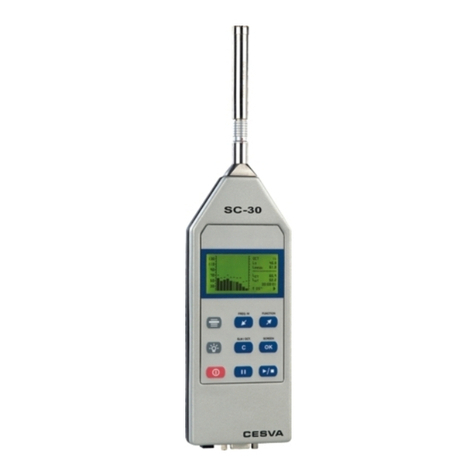
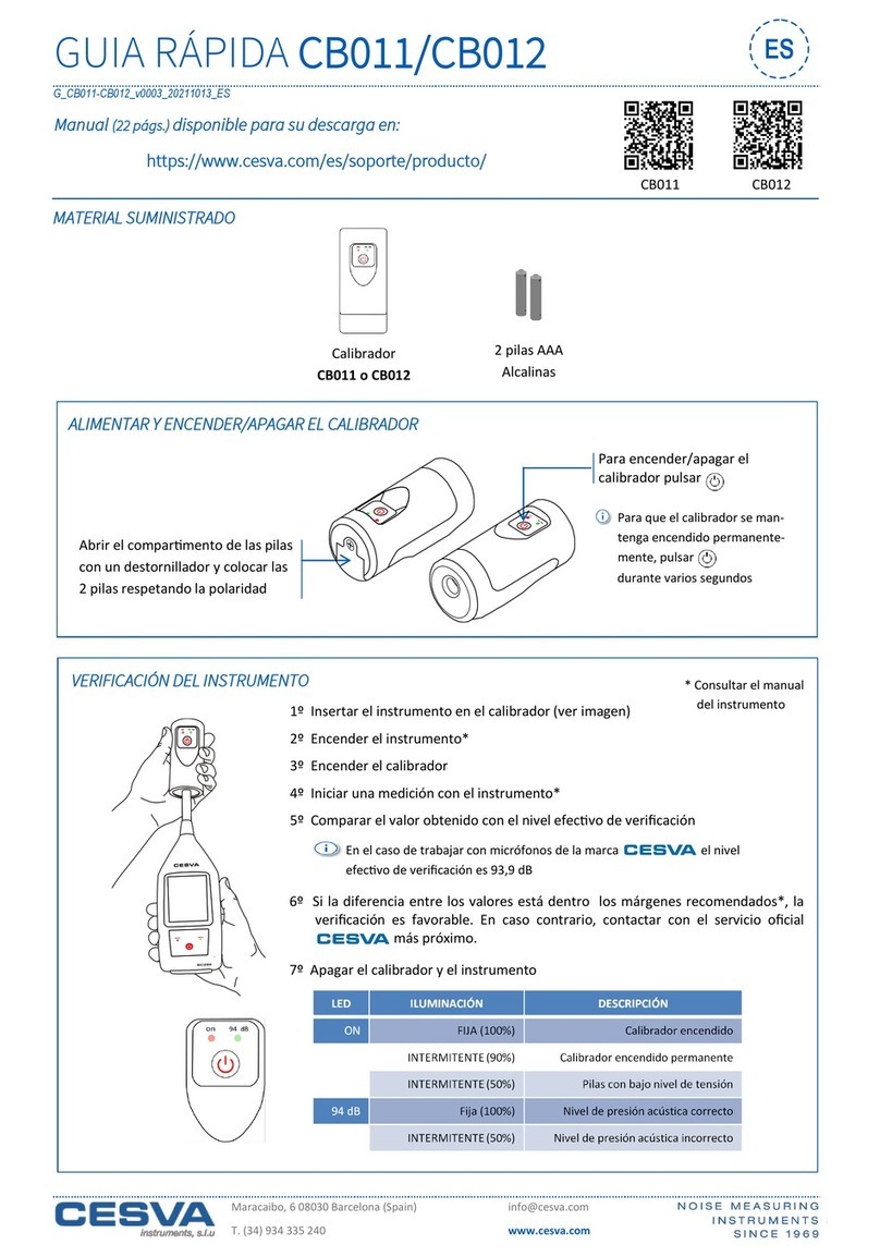
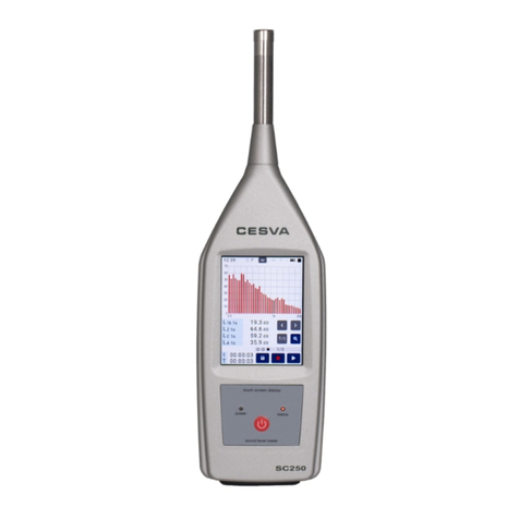
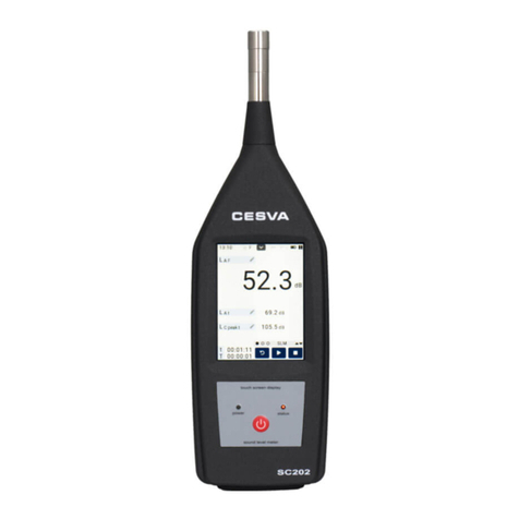
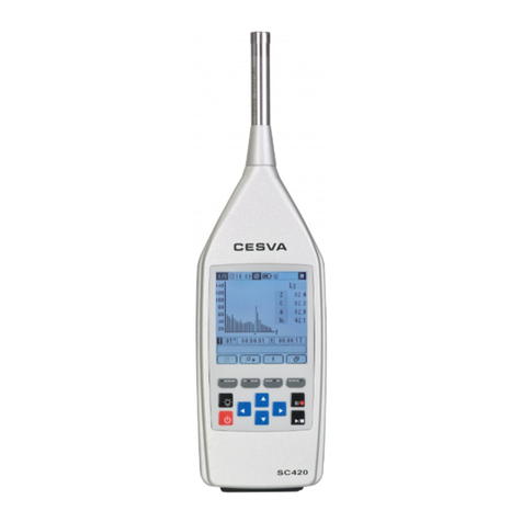
CESVA SC310 User manual

SC310
Sound Level Meter
Spectrum Analyser
User’s Manual
M
_
SC310
_
v0033
_
20070502
_
ENG

NOTE: This version of the manual is valid for
instruments with serial number from T224599

SC310
User’s Manual
1
ENGLISH
CONTENTS
1. GENERAL FEATURES .......................................................................................................7
1.1 Workings modes and functions.......................................................................................7
1.2 Main features of the SC310 ..........................................................................................10
1.3 Description of the SC310 ..............................................................................................12
1.4 Screen...........................................................................................................................14
1.5 Using the keyboard .......................................................................................................14
2. USING THE SC310............................................................................................................17
2.1 First steps .....................................................................................................................17
2.1.1 Material and literature.........................................................................................17
2.1.2 SC310 power supply...........................................................................................17
2.1.3 Connecting and disconnecting the preamplifier, using the extension cable, the
windscreen and the outdoor kit........................................................................................18
2.2 Beginning a measurement ............................................................................................20
2.2.1 Starting the SC310 .............................................................................................20
2.2.2 Selecting the measurement mode......................................................................20
2.2.3 Checking the SC310...........................................................................................23
2.3 Measuring in sound level meter mode ..........................................................................24
2.3.1 Prior adjustments: Preferential screen and integration time...............................25
2.3.2 Beginning a measurement..................................................................................26
2.3.3 Functions display................................................................................................26
2.3.4 Interrupting measurement...................................................................................29
2.3.5 Consulting measured data..................................................................................30
2.4 Measuring in spectrum analyser mode 1/1 ...................................................................30
2.4.1 Prior adjustments: integration time .....................................................................30
2.4.2 Beginning measurement.....................................................................................31
2.4.3 Functions display................................................................................................31
2.4.4 Stopping measurement.......................................................................................34
2.4.5 Consulting the measured data............................................................................35
2.5 Measuring in spectrum analyser 1/3 mode ...................................................................35
2.5.1 Prior adjustments: Integration time....................................................................35
2.5.2 Beginning measurement.....................................................................................36
2.5.3 Functions display................................................................................................36
2.5.4 Interrupting measurement...................................................................................37
2.5.5 Consulting measured data..................................................................................38
2.6 Overload indicator.........................................................................................................38
2.7 SC310 menu: Register and setting management .........................................................38
2.7.1 Access to the menu ............................................................................................38
2.7.2 The SC310 menu................................................................................................39
2.7.3 Register management ........................................................................................39
2.7.4 Printing................................................................................................................39
2.7.5 Settings...............................................................................................................40
2.8 Turning the SC310 off...................................................................................................42
2.9 Warnings and precautions ............................................................................................42
2.10 Advice for carrying out measurements........................................................................43

2
3. DATA REGISTERING........................................................................................................45
3.1 Saving results ...............................................................................................................45
3.2 Carrying out a recording ...............................................................................................46
3.2.1 Time synchronisation..........................................................................................46
3.3 Kinds of recording .........................................................................................................47
3.3.1 Recording in sound meter mode.........................................................................47
3.3.2 Recording in spectrum analyser 1/1 mode .........................................................48
3.3.3 Recording in spectrum analyser 1/3 mode .........................................................49
3.3.4 Circular memory .................................................................................................51
3.4 Viewing the register ......................................................................................................51
3.5 Erasing the memory......................................................................................................51
4. DATA TRANSFER AND PRINT-OUT ...............................................................................52
4.1 AC output: recording of calibrated measurements........................................................52
4.2 RS-232 communications port........................................................................................53
4.3 USB communications port.............................................................................................54
4.4 Data transfer to a PC: communication software............................................................54
5. TECHNICAL SPECIFICATIONS .......................................................................................56
5.1 Measurement range......................................................................................................56
5.2 Detector - Functions LF, LSand LI.................................................................................58
5.3 Peak detector - Lpeak function.........................................................................................58
5.4 Integrator - LT, Ltand LEfunctions.................................................................................58
5.5 Display update rates .....................................................................................................59
5.6 Frequency weighting.....................................................................................................59
5.7 AC output ......................................................................................................................60
5.8 Octave band filters ........................................................................................................60
5.9 Measurement range (octave band spectrum analyser).................................................61
5.10 Third octave band filters..............................................................................................61
5.11 Measurement range (one third octave spectrum analyser).........................................62
5.12 Microphone .................................................................................................................62
5.13 Diffuse field sensitivity (S)...........................................................................................64
5.14 Directivity ....................................................................................................................65
5.15 Effect of the accessories on the microphone ..............................................................66
5.16 Reference conditions ..................................................................................................68
5.17 Warm-up time .............................................................................................................68
5.18 Temperature influence ................................................................................................68
5.19 Humidity influence.......................................................................................................68
5.20 Electromagnetic compatibility......................................................................................68
5.21 Vibration influence ......................................................................................................69
5.22 Batteries & External supply.........................................................................................69
5.23 Dimensions and weight...............................................................................................69
5.24 Preamplifier connector ................................................................................................70
5.25 Memory .......................................................................................................................70
5.26 Calibration...................................................................................................................70
5.27 Standards....................................................................................................................70
5.28 Notes...........................................................................................................................71
5.29 Accessories.................................................................................................................71
6. APPENDIX A: Functions ..................................................................................................72
6.1 Function summary table................................................................................................72
6.1.1 Sound level meter mode functions .....................................................................72
6.1.2 1/1 Spectrum analyser mode functions ..............................................................73
6.1.3 1/3 Spectrum analyser mode functions ..............................................................73

SC310
User’s Manual
3
6.2 Definition of functions....................................................................................................74
6.2.1 Sound pressure level with fast and slow time weightings...................................74
6.2.2 Sound pressure level with ‘I’ time weighting.......................................................74
6.2.3 Sound pressure peak level .................................................................................75
6.2.4 Equivalent continuous sound pressure level ......................................................75
6.2.5 Sound exposure level (SEL)...............................................................................75
6.2.6 Percentile levels..................................................................................................76
7. APPENDIX B: Reverberation Time Module ....................................................................77
7.1 Activation of the Reverberation Time Module ...............................................................77
7.2 Using the keyboard .......................................................................................................78
7.3 Using the SC310...........................................................................................................78
7.3.1 Switch on the SC310 ..........................................................................................78
7.3.2 Access to the Reverberation Time Mode 1/1.....................................................78
7.3.3 Access to the Reverberation Time Mode 1/3.....................................................78
7.3.4 End the SC310 ...................................................................................................79
7.3.5 SC310 menu.......................................................................................................79
7.4 Measuring the Reverberation Time by octave bands....................................................79
7.4.1 Measuring the Reverberation Time ....................................................................79
7.4.2 Beginning a measurement..................................................................................79
7.4.3 Stopping the measurement.................................................................................81
7.4.4 Overload indicator...............................................................................................81
7.4.5 Indicator (---).......................................................................................................82
7.5 Measuring the Reverberation Time by one third octave bands.....................................82
7.5.1 Measuring the Reverberation Time ....................................................................82
7.5.2 Visualizing the third octave bands ......................................................................82
7.5.3 Beginning a measurement..................................................................................83
7.5.4 Stopping the measurement.................................................................................84
7.5.5 Overload indicator) .............................................................................................85
7.5.6 Indicator (---).......................................................................................................85
7.6 Data register .................................................................................................................85
7.6.1 Saving results .....................................................................................................85
7.6.2 View register.......................................................................................................86
7.7 Technical Specifications................................................................................................87
7.7.1 Measurement Range ..........................................................................................87
7.7.2 Estimation of the slope of the decay curve.........................................................89
7.7.3 Standards of measurement and calculation .......................................................89
7.8 Function summary table................................................................................................90
7.8.1 Reverberation time mode functions....................................................................90
7.9 Definition of functions....................................................................................................90
7.9.1 Decay curve........................................................................................................90
7.9.2 Reverberation Time ............................................................................................90
8. APPENDIX C: Extended frequency module ...................................................................92
8.1 Activation of the Extended frequency analysis module.................................................92
8.2 Using the keyboard for 1/3 Extended Spectrum Analyser Mode ..................................93
8.3 Using the keyboard for the FFT Narrow Band Frequency Analyser Mode ...................93
8.4 Using the SC310...........................................................................................................94
8.4.1 Switch on the SC310 .........................................................................................94
8.4.2 Access to the 1/3 extended Spectrum Analyser.................................................94
8.4.3 Access to the FFT Narrow Band Frequency Analyser........................................94
8.4.4 End the SC310 ...................................................................................................94
8.4.5 SC310 menu.......................................................................................................94
8.5 Measuring in 1/3 extended Spectrum Analyser mode ..................................................95
8.5.1 Prior adjustments: Integration time....................................................................95

4
8.5.2 Beginning measurement.....................................................................................95
8.5.3 Functions display................................................................................................96
8.5.4 Interrupting the measurement.............................................................................98
8.5.5 Consulting measured data..................................................................................98
8.5.6 Overload indicator...............................................................................................99
8.6 Measuring in FFT Narrow Band frequency Analyser Mode ..........................................99
8.6.1 Prior adjustments: Integration time....................................................................99
8.6.2 Beginning measurement...................................................................................100
8.6.3 Functions display..............................................................................................100
8.6.4 Interrupting the measurement...........................................................................102
8.6.5 Consulting measured data................................................................................102
8.6.6 Overload indicator.............................................................................................102
8.7 Data registering...........................................................................................................102
8.7.1 Saving results ...................................................................................................103
8.7.2 Carrying out a recording ...................................................................................103
8.7.3 Time synchronisation........................................................................................104
8.7.4 Kinds of recording.............................................................................................104
8.8 Circular memory..........................................................................................................106
8.9 Viewing the register ....................................................................................................106
8.10 Technical specifications ............................................................................................107
8.10.1 Third octave band filters ...................................................................................107
8.10.2 Measurement range (one third octave spectrum analyser) ..............................108
8.10.3 Standards .........................................................................................................108
8.11 Function summary table............................................................................................109
8.11.1 1/3 Extended Spectrum analyser mode functions ............................................109
8.12 FFT narrow band frequency analyser .......................................................................110
9. APENDIX D: Dosimeter Module for the assessment of noise at workplace .............111
9.1 Dosimeter module activation.......................................................................................111
9.2 Using the keyboard for the dosimeter mode ...............................................................112
9.3 Using the SC310.........................................................................................................112
9.3.1 Switch on the SC310 ........................................................................................112
9.3.2 Accessing to the Dosimeter mode....................................................................113
9.3.3 Turn off the SC310 ...........................................................................................113
9.3.4 SC310 Menu.....................................................................................................113
9.4 Measuring in dosimeter mode.....................................................................................113
9.4.1 Prior adjustments..............................................................................................113
9.4.2 Beginning measurement...................................................................................114
9.4.3 Function display................................................................................................115
9.4.4 Interrupting the measurement...........................................................................117
9.4.5 Consulting measured data................................................................................117
9.4.6 Overload indicator.............................................................................................117
9.5 Data registering...........................................................................................................117
9.5.1 Saving final results............................................................................................117
9.5.2 Making a recording ...........................................................................................118
9.5.3 Time synchronisation........................................................................................118
9.5.4 Kinds of recording.............................................................................................119
9.6 Circular memory..........................................................................................................120
9.7 View the register .........................................................................................................120
9.8 Technical specifications. .............................................................................................121
9.8.1 Standards .........................................................................................................121
9.9 Functions definitions ...................................................................................................121
9.9.1 Daily noise exposure level................................................................................121
9.9.2 Sound exposure................................................................................................121
9.9.3 Dose .................................................................................................................121

SC310
User’s Manual
5
10. APENDIX E: Module for vibration measurements.....................................................122
10.1 Vibration measurement kit ........................................................................................122
10.1.1 Reception of the vibration measurement kit .....................................................122
10.1.2 Vibration measurement module activation........................................................123
10.1.3 PA001 Preamplifier and the Accelerometer connection ...................................123
10.1.4 If you want to connect a different accelerometer..............................................124
10.1.5 Extension Cables..............................................................................................124
10.2 Using the keyboard for the vibration mode ...............................................................125
10.3 Using the keyboard for the FFT narrow band frequency analysis.............................125
10.4 Using the SC310.......................................................................................................126
10.4.1 Starting the SC310 ...........................................................................................126
10.4.2 Accessing to the Vibration mode ......................................................................126
10.4.3 Accessing to the FFT narrow band frequency analysis mode..........................126
10.4.4 Turn off the SC310 ...........................................................................................126
10.4.5 SC310 Menu.....................................................................................................126
10.5 Measuring in Vibration mode ....................................................................................127
10.5.1 Prior adjustments: Sensitivity............................................................................127
10.5.2 Prior adjustments: Evaluation time ...................................................................128
10.5.3 Beginning measurement...................................................................................129
10.5.4 Function display................................................................................................129
10.5.5 Interrupting the measurement...........................................................................132
10.5.6 Consulting measured data................................................................................132
10.5.7 Overload indicator.............................................................................................132
10.6 Measuring FFT Narrow Band Frequency Analysis ...................................................132
10.6.1 Prior adjustments: Sensitivity............................................................................133
10.6.2 Prior adjustments: Evaluation time ...................................................................134
10.6.3 Beginning the measurement.............................................................................135
10.6.4 Function display................................................................................................135
10.6.5 Interrupting the measurement...........................................................................137
10.6.6 Consulting measured data................................................................................137
10.6.7 Overload indicator.............................................................................................138
10.7 Data registering.........................................................................................................138
10.7.1 Saving final results............................................................................................138
10.7.2 Making a recording ...........................................................................................139
10.7.3 Time synchronisation........................................................................................139
10.7.4 Kinds of recording.............................................................................................139
10.8 Circular memory........................................................................................................141
10.9 View the register .......................................................................................................142
10.10 Technical specifications ..........................................................................................143
10.10.1 One third octave band filters.............................................................................143
10.10.2 Frequency weighting.........................................................................................143
10.10.3 Standards .........................................................................................................144
10.11 Function summary table..........................................................................................145
10.11.1 Vibration mode functions ..................................................................................145
10.12 Function definitions .................................................................................................146
10.12.1 Average acceleration with frequency weighting Wmand evaluation time T......146
10.12.2 Acceleration level..............................................................................................146
10.12.3 Peak acceleration .............................................................................................146
10.12.4 Crest factor .......................................................................................................146
10.12.5 Maximum Transient Vibration Value.................................................................146
10.12.6 Vibration Dose Value........................................................................................147
10.12.7 Multiplying factor K ..........................................................................................147
10.12.8 Narrow band frequency analysis for vibration...................................................148

6

SC310
User’s Manual
7
1. GENERAL FEATURES
The SC310 is a powerful, user-friendly instrument for acoustic measurements. It can work as
a type-1 integrating-averaging sound level meter that complies with IEC 61672 international
standard and its EU counterpart EN 61672 also complies with IEC 60651 and IEC 60804
international standards and their EU counterparts EN 60651 and EN 60804. The SC310 also
complies with the American standards ANSI S1.4 and ANSI S1.43.
The SC310 is also a spectrum analyser measuring in real time and in one third octave bands
and octave bands, with type 1 filters, which comply with IEC 61260 and EN61260. They also
comply with ANSI S1.11.
Moreover, the SC310 offers the possibility to be upgraded with different modulus to carry out
advanced acoustic measurements.
1.1 Workings modes and functions
The SC310, in its basic version (without modulus), has the following modes of working:
•Statistical Integrating Sound Level Meter
•Octave band real time spectrum analyser
•One third octave band real time spectrum analyser
As Sound Level Meter (S) it measures in the whole dynamic range (single scale) and
simultaneously the following functions:
•The sound pressure level with ‘S’, ‘F’ and ‘I’ time averaging. And their maximum and
minimum values during the measurement period and each second *
•The peak sound pressure level corresponding to the measurement time and each second *
•The sound exposure level, also known as SEL.
•The equivalent continuous sound pressure level with programmable consecutive
integration time T and its maximum and minimum values, also known as Leq.
•The equivalent continuous sound pressure level with integration time one second*
•The equivalent continuous sound pressure level during the measurement period.
•The equivalent continuous sound pressure level with time averaging ‘I’ and programmable
consecutive integration time T and integration time belonging to the measurement period.
•125 ms Functions* (short functions):
oThe Sound pressure level with ‘S’, ‘F’ and ‘I’ time weighting, sampled every
125 ms. 8 values per second*
oThe Peak sound pressure level corresponding to the latest 125 ms. 8 values
per second*
oThe equivalent continuous sound pressure level with consecutive integration
time of 125 milliseconds (Short Leq). 8 values per second*
All these functions are measured simultaneously with the following frequency weightings:
•Frequency Weighting A
•Frequency Weighting C

8
•Frequency Weighting Z (zero): Frequency Weighting equal to 0 dB from 10 Hz to 20 kHz
It also measures the following functions:
•The total percentile levels corresponding to 1, 5, 10, 50, 90, 95 and 99 % of the entire
measurement and the partial levels of each T interval of the sound pressure level with time
averaging ‘F’ and frequency weighting A.
The SC310 also displays the following acoustic functions:
•The subtraction of the equivalent continuous sound pressure level with time averaging ‘I’
and the equivalent continuous sound pressure level, corresponding to the measurement
time and to the programmable integration time T. These two functions measured with
frequency weighting A, C and Z
•The subtraction of the equivalent continuous sound pressure level with frequency
weighting C and the equivalent continuous sound pressure level with frequency weighting
A, corresponding to the measurement time and to a programmable integration time T.
As an octave band spectrum analyser (1/1), it measures simultaneously and in all the
dynamic range (single scale) the following functions:
•The equivalent continuous sound pressure level with programmable consecutive
integration time T and without frequency weighting for each octave band centred on
frequencies of 31.5, 63, 125, 250, 500, 1000, 2000, 4000, 8000 and 16000 Hz.
•The equivalent continuous sound pressure level with programmable consecutive
integration time of 125 ms and without frequency weighting for each octave band centred
on frequencies of 31.5, 63, 125, 250, 500, 1000, 2000, 4000, 8000 and 16000 Hz *
•The equivalent continuous sound pressure level of the integration time 125 ms and with
frequency weighting A, C and Z *
•The maximum of the peak sound pressure level corresponding to the 125 ms integration
interval with frequency weighting A, C and Z.
•The equivalent continuous sound pressure level of the T integration interval with frequency
weighting A, C and Z.
•The maximum of the peak sound pressure level for the T integration interval with
frequency weighting A, C and Z.
•The partial percentile levels corresponding to 1, 5, 10, 50, 90, 95 and 99 % of the
equivalent continuous sound pressure level corresponding to the integration time T
measured for each octave band.
•The overall percentile levels corresponding to 1, 5, 10, 50, 90, 95 and 99 % of the total
equivalent continuous sound pressure level measured with frequency weighting A and
corresponding to the integration time T.
The SC310 has a background noise evaluation screen where the following acoustic functions
are shown:
•The value of the NC (Noise Criterion) curve corresponding to the measured spectrum
•The value of the NC curve that has not been exceeded in each octave band
As a one third octave band spectrum analyser (1/3), it measures simultaneously and in all
the dynamic range (single scale) the following functions:

SC310
User’s Manual
9
•The equivalent continuous sound pressure level with programmable consecutive
integration time T and without frequency weighting for each one third octave band centred
on frequencies of 20, 25, 31.5, 40, 50, 63, 80, 100, 125, 160, 200, 250, 315, 400, 500, 630,
800, 1000, 1250, 1600, 2000, 2500, 3150, 4000, 5000, 6300, 8000 and 10000 Hz
•The equivalent continuous sound pressure level with programmable consecutive
integration time of 125 ms and without frequency weighting for each one third octave band
centred on frequencies of 20, 25, 31.5, 40, 50, 63, 80, 100, 125, 160, 200, 250, 315, 400,
500, 630, 800, 1000, 1250, 1600, 2000, 2500, 3150, 4000, 5000, 6300, 8000 and 10000
Hz*
See APPENDIX A: Functions for the names and definitions of each of the functions measured.
* The functions in italics are measured by the SC310 but are not shown on its screen. The way to get the
results of these functions is to make a real time measurement with the Capture Studio software application
or making a recording and downloading the results to a PC with the help of Capture Studio (see chapter
4).

10
1.2 Main features of the SC310
The SC310 is an easy-to-use sound level meter that allows you to make sound
measurements quickly and conveniently. The SC310 measures simultaneously a wide range
of functions, with which it is possible to calculate the most important acoustic evaluation
indexes of the majority of countries in the world. The SC310 makes a quantitative analysis
(sound level meter parameters, spectral levels) and qualitative (impulsiveness indicators, low
frequency, background noise evaluation in rooms, etc.)
The most important features of the SC310 are the following:
•The SC310 has been designed to be user friendly; a single reading of the manual will allow
you to work intuitively with it.
•The SC310 has a single user range; there is therefore no need to adjust the scale prior to
beginning a measurement, whatever the dynamic range of the sound event to be
measured.
•Whether you use it as a sound level meter or spectrum analyser, the SC310
simultaneously measures all functions with all the available frequency weightings (A, C
and Z).
•The SC310 preamplifier is detachable. You can uncouple it and move it away from the
SC310 by using the extension cable (CN-003, CN-010 or CN-030). The instrument can be
complemented with an outdoor kit (TK1000) for taking measurements in the open air.
•The SC310 is equipped with CAPTURE STUDIO communications software, allowing you
to configure the instrument and download all the recorded data and real-time
measurements into a personal computer. This way they can be viewed in electronic
format, exported to other programmes and its data show in numeric and graphic format to
generate reports. See 4.4
•The SC310 AC output is designed to pick up the direct preamplifier signal. This allows you
to make a calibrated recording on a D.A.T. and subsequently analyse it both quantitatively
(impulse or tonal sound level analysis) and qualitatively (exceptional sound event – shouts,
undesirable noises, etc. – detection). The SC310 is equipped with a 40 dB built-in amplifier
to adapt the measurement range to the recording dynamic range. See 4.1.
•The SC310’s graphic screen displays the measured functions in both graphic and
alphanumeric formats. The graphic display is highly practical when it comes to studying a
sound event, evaluating its time history or analysing its spectral contents. The SC310’s
screen lights up at the push of a button, allowing you to work in dim conditions or in the
dark.
•The SC310’s membrane keyboard is absolutely flat. This way its excellent sound response
is never impaired.
•The SC310 has an internal memory for storing measured data. The storage of these data
in the memory is configurable, allowing you to adapt the form of data recording to the kind
of measurement being conducted. See chapter 3.
•The SC310 allows you to download data stored in memory simultaneously to the process
of measuring and recording. This feature together with the possibility to configure the free
space of memory as a circular memory identifies the SC310 as the perfect platform for
permanent acoustic monitoring. See 3.3.4.
•The SC310 has multiple language support and once a language is selected, it will remain
selected even if the unit is turned OFF (see paragraph 2.7.5)
•The SC310 stores in memory the time and date of the last time the sensitivity was
modified. (See 2.2.3)

SC310
User’s Manual
11
•The SC310 can work with both 200 V polarised and prepolarised microphones. Each kind
of microphone needs its corresponding preamplifier to work correctly.
•The SC310 has two communication ports: RS-232 and USB. The USB port allows data to
be downloaded at high speed rate and the RS-232 offers compatibility with all the
computers and permits to generate communication ports through modem (telephone,
mobile) or Wireless. See 4.2.
•SC310 and CAPTURE STUDIO are compatible with the Wireless technology. This
wireless technology makes possible the connection to CAPTURE STUDIO, inside a radius
of 100 m, of several SC310 sound level meters simultaneously. In this way, several sound
level meters can be converted in a multi-channel system of high features.

12
1.3 Description of the SC310
The main components of the SC310 are listed below, the numbers corresponding to those in
the outline drawing:
1. ½’’ condenser microphone. The SC310 works with either the C-130 microphone
(polarised at 200 V) + PA-13 preamplifier or the C-250 pre-polarised microphone +
Pa-14 preamplifier. Both models are precision condenser microphones. The SC310 is
a type-1 sound level meter whichever microphone is used.
2. Preamplifier. The SC310 is equipped with the removable PA-13 preamplifier (for C-
130) or the PA-14 type (for C-250), which is connected by the LEMO connector [3].
3. LEMO-type preamplifier connector. LEMO-type male plug preamplifier connector.
4. LEMO-type sound level meter connector. LEMO-type SC310 sound level meter
socket connector.
5. Screen. Illuminated LCD graphic screen.
6. Membrane keyboard. Extra-flat keyboard designed to reduce the reflections that
may reach the microphone from the sound level meter case.
7. Characteristics plate. Showing the make, model and serial number of the sound
level meter, along with all the standards it complies with as type 1.
8. CE mark. European approval mark.
9. Tripod mount. Built-in support for tripod with standard ¼” W thread (TR-40).
10. WEEE mark. Symbol indicating separate collection for electrical and electronic
equipment.
11. Battery cover. To change the battery, simply remove the cover.
12. AC output.Direct output from the preamplifier without frequency weighting. Specially
designed to make recordings on D.A.T. medium.
13. USB Connector: mini-B USB type connector for digital bi-directional communication
digital USB 1.1 full speed.
14. RS-232 input/output connector.SubD-type 9 pin-connector for serial connection of
the sound level meter to a personal computer and phone connection through modem.
15. DC input: Input with which to connect to a DC mains supply (5 V, 100 mA). (AM240
or AM241)

SC310
User’s Manual
13

14
1.4 Screen
The current SC310 mode is always indicated in the top right-hand corner of the screen:
•Sound Level meter mode
•Octave band Spectrum Analyser
•One third octave band Spectrum Analyser
While the SC310 is measuring, the following information appears at the bottom right of the
screen:
•The elapsed measurement time t
•The elapsed integration time (between 0 and T).
(For LT the SC310 carries out consecutive
integrations of T time, whether it is functioning as
a sound level meter or spectrum analyser)
•The T integration time (for LT only)
•State of measurement indication:
measurement completed
measurement in progress
(flashing) measurement with recording in
progress
measurement temporarily paused
Hint: Do not confuse the elapsed measuring time (t) with the integration time (T)
1.5 Using the keyboard
The following tables show the function of the different keys of the SC310.
GENERAL KEYS:
Key for switching the SC310 on and off (RED)
Key for turning the screen light on and off

SC310
User’s Manual
15
SC310 MENU KEYS:
Key to access the SC310 menu
Key for moving downwards in the menu
Key for moving upwards in the menu
Key for confirming or switching options
Key for returning to the previous menu
SC310 SOUND LEVEL METER KEYS:
Key to begin or finish a measurement
a. Key to temporarily interrupt a measurement (PAUSE)
(while the SC310 is in )
b. To start recording data into memory (when SC310 is
stopped i.e. )
Key to select the frequency weighting displayed on the
screen
Key to select the function displayed on the screen
Key to select the desired sound level meter screen:
numerical, graphic, statistical or advanced
Key to switch from sound level meter to 1/1 spectrum
analyser
Key to access the preferred numerical screen, from the
numerical screen only
SC310 1/1 OCTAVE SPECTRUM ANALYSER KEYS:
Key to begin or finish a measurement
a) Key to temporarily interrupt a measurement (PAUSE)
(while the SC310 is in )
b) To begin recording (when SC310 is in )
Key to return to the previous octave band
Key to go on to the next octave band
Key to select the desired 1/1 spectrum analyser screen:
numerical, graphic, statistical or NC
Key to switch from the 1/1 spectrum analyser to 1/3
spectrum analyser

16
SC310 1/3 OCTAVE SPECTRUM ANALYSER KEYS:
Key to begin or finish a measurement
c) Key to temporarily interrupt a measurement (PAUSE)
(while the SC310 is in )
d) To begin recording (when SC310 is in )
Key to return to the previous third octave band
Key to go on to the next third octave band
Key to select the desired 1/3 spectrum analyser screen:
numerical spectrum analysis or graphic spectrum analysis
Key to switch from the 1/3 spectrum analyser to the sound
level meter mode

SC310
User’s Manual
17
2. USING THE SC310
This chapter contains all the information you need to configure and adjust the SC310 and
carry out sound level and spectrum measurements.
2.1 First steps
This section tells you what to do before starting to use the SC310.
2.1.1 Material and literature
The first step is to check that all the material and literature supplied with the SC310 is there:
Material:
•SC310 sound level meter
•Case
•Wind screen
•Two 1.5 V alkaline batteries size AA (LR6)
•USB-USB connection cable to connect the instrument to a PC
•Communication software to download data into a PC: Capture Studio
Literature:
•Sound level meter User’s Manual
•Warranty
•Verification certificate
Should anything be missing, get in touch with your official distributor.
2.1.2 SC310 power supply
Before you turn the SC310 on, the first thing you must do
is connect it to a battery or other power supply.
The SC310 sound level meter is fed by two 1,5 V alkaline
or lithium batteries sized AA (LR6) or by direct current
[15]. For DC supply use the AM240 (V= 230
V, 50 Hz) or AM241 (V= 110 V, 60 Hz) model mains
feeder. If both systems are used at the same time, the
SC310 selects the one offering the higher voltage. The
maximum permitted input voltage is 5 volts. This means
a “12 V” car battery should only be connected to the
SC310 through the AM140 converter.
When the SC310 is fed by the DC input, the symbol
will appear in the bottom right-hand corner of the screen
To fit the batteries, raise the battery compartment lid [11]
at the rear of the SC310. Insert the batteries as indicated
in the drawing that appears inside the batteries 2
1
1

18
compartment; to do that press the negative pole against
the spring and fit the battery so that the positive pole
presses against the flat metallic contact.
When the battery is insufficiently charged to allow the
SC310 to work properly, a battery icon appears in the
bottom right-hand corner of the sound level meter screen
(see figure).
When this icon appears, the SC310 batteries must be
replaced. The SC310 will show the symbol for 5 minutes
and if a measurement or a recording is in progress, it
will stop it and will show the message “BATTERY FLAT”
and then the SC310 will automatically switch itself off.
To replace the batteries, stop the measurement in
progress and switch the sound level meter off. To
remove the batteries, open the battery compartment and
press the battery against the spring and pull it up,
holding the battery by its positive pole, as shown in the
figure.
TIPS:
If you are not going to use the SC310 for some time, remove the battery to prevent damage
caused by battery leakage.
Make sure you always carry spare batteries with you, since you may be measuring
somewhere where it isn’t easy to find new ones
2.1.3 Connecting and disconnecting the preamplifier, using the
extension cable, the windscreen and the outdoor kit
The SC310 preamplifier is completely detachable. This allows you to move the preamplifier +
microphone set away from the sound level meter and user. In this way you can operate the
SC310 far from the place of measurement, thereby avoiding possible interference. To do
this, use the CN-003, CN-010 or CN-030 extension cable.
WARNING! When you connect or disconnect the preamplifier +
microphone set, the sound level meter must be switched off.
The preamplifier + microphone are an indivisible set, the
microphone is screwed on the preamplifier. You must not unscrew
the microphone from the preamplifier unless is strictly necessary;
the microphone could be damaged during its manipulation.
would not be responsible for manipulations carried
out by unauthorized persons and the equipment will lose its
warranty.
2 1
Table of contents
Other CESVA Measuring Instrument manuals