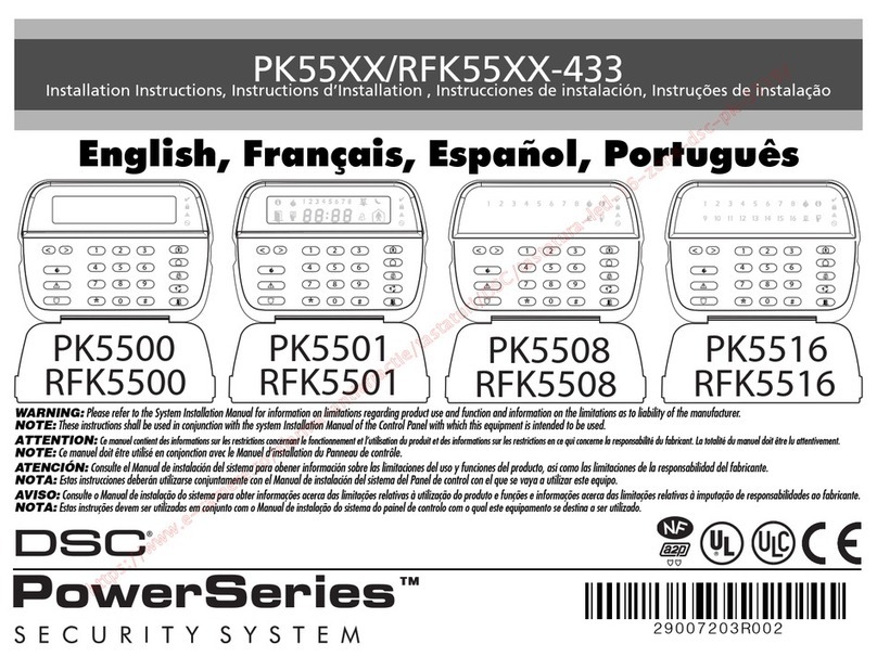
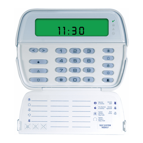
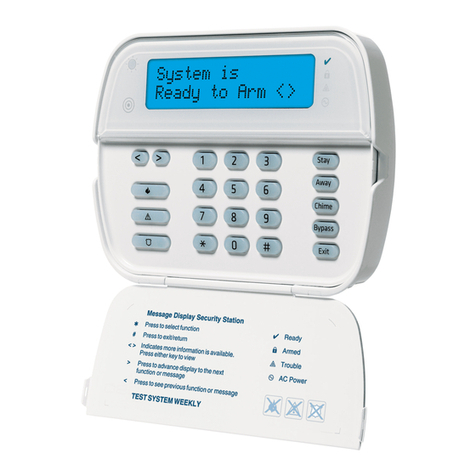
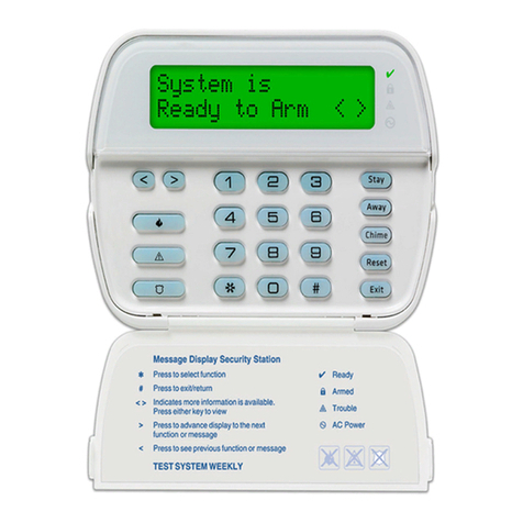
DSC LCD5501Z32-900 User manual

Installation Manual
LCD5501Z32-900
WARNING: Please refer to the System Installation Manual for information on
limitations regarding product use and function and information on the limitations as to
liability of the manufacturer.
version 1.0

LIMITED WARRANTY
Digital Security Controls Ltd. warrants the original purchaser that for a
period of twelve months from the date of purchase, the product shall be
free of defects in materials and workmanship under normal use. During
the warranty period, Digital Security Controls Ltd. shall, at its option,
repair or replace any defective product upon return of the product to its
factory, at no charge for labour and materials. Any replacement and/or
repaired parts are warranted for the remainder of the original warranty
or ninety (90) days, whichever is longer. The original owner must
promptly notify Digital Security Controls Ltd. in writing that there is
defect in material or workmanship, such written notice to be received in
all events prior to expiration of the warranty period.
International Warranty
The warranty for international customers is the same as for any cus-
tomer within Canada and the United States, with the exception that
Digital Security Controls Ltd. shall not be responsible for any customs
fees, taxes, or VAT that may be due.
Warranty Procedure
To obtain service under this warranty, please return the item(s) in ques-
tion to the point of purchase. All authorized distributors and dealers
have a warranty program. Anyone returning goods to Digital Security
ControlsLtd.mustfirstobtainanauthorizationnumber. Digital Security
Controls Ltd. will not accept any shipment whatsoever for which prior
authorization has not been obtained.
Conditions to Void Warranty
This warranty applies only to defects in parts and workmanship relating
to normal use. It does not cover:
• damageincurredinshippingorhandling;
• damage caused by disaster such as fire, flood, wind, earthquake or light-
ning;
• damageduetocauses beyond thecontrolofDigital Security ControlsLtd.
such as excessive voltage, mechanical shock or water damage;
• damage caused by unauthorized attachment, alterations, modifications or
foreignobjects;
• damage caused by peripherals (unless such peripherals were supplied by
DigitalSecurity ControlsLtd.);
• defectscausedbyfailuretoprovide a suitable installation environment for
theproducts;
• damage caused by use of the products for purposes other than those for
whichitwasdesigned;
• damagefromimpropermaintenance;
• damagearisingoutofanyotherabuse,mishandlingorimproperapplication
of the products.
Digital Security Controls Ltd.’s liability for failure to repair the product un-
der this warranty after a reasonable number of attempts will be limited to a
replacement of the product, as the exclusive remedy for breach of warranty.
Under no circumstances shall Digital Security Controls Ltd. be liable for any
special, incidental, or consequential damages based upon breach of warranty,
breach of contract, negligence, strict liability, or any other legal theory. Such
damages include, but are not limited to, loss of profits, loss of the product or
any associated equipment, cost of capital, cost of substitute or replacement
equipment, facilities or services, down time, purchaser’s time, the claims of
third parties, including customers, and injury to property.
Disclaimer of Warranties
This warranty contains the entire warranty and shall be in lieu of any
and all other warranties, whether expressed or implied (including all
implied warranties of merchantability or fitness for a particular pur-
pose) And of all other obligations or liabilities on the part of Digital
Security Controls Ltd. Digital Security Controls Ltd. neither assumes
norauthorizesanyotherpersonpurportingtoactonits behalf to modify
or to change this warranty, nor to assume for it any other warranty or
liabilityconcerning this product.
Thisdisclaimer of warranties and limitedwarranty aregovernedby the
laws of the province of Ontario, Canada.
WARNING: Digital Security Controls Ltd. recommends that the entire
system be completely tested on a regular basis. However, despite fre-
quenttesting, and due to, but not limited to, criminal tampering or elec-
trical disruption, it is possible for this product to fail to perform as ex-
pected.
Out of Warranty Repairs
Digital Security Controls Ltd. will at its option repair or replace out-of-
warranty products which are returned to its factory according to the fol-
lowing conditions. Anyone returning goods to Digital Security Controls
Ltd. must first obtain an authorization number. Digital Security Controls
Ltd. will not accept any shipment whatsoever for which prior authorization
has not been obtained.
Products which Digital Security Controls Ltd. determines to be repair-
able will be repaired and returned. A set fee which Digital Security Con-
trols Ltd. has predetermined and which may be revised from time to time,
will be charged for each unit repaired.
Products which Digital Security Controls Ltd. determines not to be repair-
able will be replaced by the nearest equivalent product available at that time.
The current market price of the replacement product will be charged for each
replacement unit.
FCC COMPLIANCE STATEMENT
CAUTION: Changes or modifications not expressly approved by Digital Security Controls Ltd. could void your authority to use this equipment.
This equipment generates and uses radio frequency energy and if not installed and used properly, in strict accordance with the manufacturer’s instructions, may cause
interference to radio and television reception. It has been type tested and found to comply with the limits for Class B device in accordance with the specifications in
Subpart “B” of Part 15 of FCC Rules, which are designed to provide reasonable protection against such interference in any residential installation. However, there is no
guarantee that interference will not occur in a particular installation. If this equipment does cause interference to television or radio reception, which can be determined
by turning the equipment off and on, the user is encouraged to try to correct the interference by one or more of the following measures:
•Re-orient the receiving antenna
•Relocate the alarm control with respect to the receiver
•Move the alarm control away from the receiver
•Connect the alarm control into a different outlet so that alarm control and receiver are on different circuits.
If necessary, the user should consult the dealer or an experienced radio/television technician for additional suggestions. The user may find the following booklet prepared
by the FCC helpful: “How to Identify and Resolve Radio/Television Interference Problems”. This booklet is available from the U.S. Government Printing Office,
Washington, D.C. 20402, Stock # 004-000-00345-4.
T A B L E O F C O N T E N T S
Table of Contents
Introduction 1
Section 1: Installation 2
1.1 Unpacking .......................................................................................................................................................... 2
1.2 Mounting............................................................................................................................................................. 2
1.3 Wiring ................................................................................................................................................................... 2
1.4 Applying Power ................................................................................................................................................. 2
1.5 Enrolling the Keypad......................................................................................................................................... 2
Section 2: Keypad Programming 4
2.1 Programming the Keypad ............................................................................................................................... 4
2.2 Function Key Options........................................................................................................................................ 4
2.3 Clock Options .................................................................................................................................................... 4
2.4 Alarms Displayed While Armed Option ......................................................................................................... 5
2.5 Emergency (Fire, Auxiliary, Panic) Key Options ........................................................................................... 5
2.6 Door Chime Options ......................................................................................................................................... 5
Section 3: Receiver Programming 7
Enroll & Program Devices 7
3.1 Electronic Serial Numbers ................................................................................................................................7
3.2 Enroll Wireless Devices Using Zones ................................................................................................................ 7
3.3 Enroll & Program Wireless Keys ........................................................................................................................ 8
3.4 Identified Wireless Keys..................................................................................................................................... 8
3.5 Enrolling & Programming Handheld Keypads.............................................................................................. 9
3.6 Deleting Wireless Devices .............................................................................................................................. 10
Section 4: Other Programming 11
4.1 Program Zones and Partitions ....................................................................................................................... 11
4.2 Enable Receiver Supervision ......................................................................................................................... 11
4.3 Enable Supervision of Wireless Zones ........................................................................................................... 11
4.4 RF Jam Detect Zone ....................................................................................................................................... 12
4.5 Receiver Software Default............................................................................................................................. 12
Section 5: Testing & Mounting 13
5.1 Test the placement of WLS904, WLS905, WLS906,
WLS907, and WLS915 devices........................................................................................................................ 13
5.2 Test WLS908, WLS909 and WLS910 Reception............................................................................................. 13
5.3 Battery Test for WLS908 Panic Pendants ...................................................................................................... 14
Section 6: Additional Notes 15
6.1 Trouble Conditions .......................................................................................................................................... 15
6.2 Replacing Batteries in Wireless Devices ...................................................................................................... 15
Section 7: Troubleshooting 16
Section 8: Programming Worksheets 17
Appendix A: Guidelines for Locating Smoke Detectors 24
Limited Warranty back cover

1
Introduction
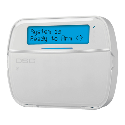
The LCD5501Z32-900 keypad combines a stan-
dard PC5132 receiver with an LCD5501Z keypad
that presents system status using an LCD-style
display with fixed messages. The keypad can be
used on security systems with up to 32 zones. The
LCD5501Z32-900 is compatible with the following
DSC security systems:
• PC580/585 v2.3 and higher
• PC1555 v2.3 and higher
• Power608 v2.3 and higher
• PC5008 v2.3 and higher
• PC5010 v2.0 and higher
• PC5015 v2.2 and higher
Specifications and Features
• Current Draw: 260mA
• Frequency: 922 to 926 MHz, Spread Spectrum
• Zones - receiver can receive signals from up to 32
wireless zones
• Supervisory - programmable supervisory window,
one to 24 hours
• Location
- canbewiredupto1000ft./305mfromthemainpanel
with 22 gauge wire
- forlongerwireruns,thickergaugewiremustbeused.
• Compatibility: The LCD5501Z32-900 can be
connected to the following panels: PC5010, PC5015,
PC5008, PC1555, PC580
• Connects to control panel via 4-wire Keybus
• One keypad zone input
• Optional tamper version
• Five programmable function keys
• Ready (green), Armed (red) and Trouble (yellow)
status lights
Introduction
I N T R O D U C T I O N

2
1.1 Unpacking
The LCD5501Z32-900 package includes the following
parts:
• One LCD5501Z32-900 keypad
• Four mounting screws
• One keypad inner door label
• One set of Fire, Auxiliary and Panic key labels
1.2 Mounting
You should mount the keypad where it is accessible
to designated points of entry and exit. Once you
have selected a dry and secure location, perform
the following steps to mount the keypad:
1. Remove the keypad backplate by loosening the
screw located at the base of the unit.
2. Secure the keypad backplate to the wall in the
desired location. Use the screws provided.
3. Before attaching the keypad to its backplate,
complete the keypad wiring as described in the
next section.
1.3 Wiring
1. Before beginning to wire the unit, ensure that all
power (AC transformer and battery) is
disconnected from the control panel.
2. Connect the four Keybus wires from the control
panel(red,black,yellowandgreen)tothe keypad
terminals (R B Y G). Consult the diagram below:
Installation
S E C T I O N 1
3. Youcanconnect a device- such asa doorcontact
- to the “Z” terminal of the LCD5501Z32-900. This
eliminatestheneedto runwiresbacktothecontrol
panel for the device. To connect the zone, run
one wire from the device to the Z terminal and the
otherwirefromthedeviceto the B(black)terminal.
For powered devices, run the red wire to the R
(positive) terminal and the black wire to the B
(negative) terminal. When using end of line
supervision, connect the zone according to one
of the configurations outlined in your system’s
Installation Manual
.
1.4 Applying Power
Once all wiring is complete, apply power to the
control panel:
1. Connect the battery leads to the battery.
2. Connect the AC transformer.
For more information on control panel power
specifications, see the control panel
Installation
Manual
.
NOTE: Do not connect the power until all wiring is
complete.
1.5 Enrolling the Keypad
Once all wiring is complete, you will need to enter a
2-digit number that tells the system the partition
and slot assignment of the keypad.
If your system has partitions, you will need to also
assign the keypad to a partition (1st digit).
The slot assignment (2nd digit) tells the panel
which keypad slots are occupied. The panel can
then generate a fault when a keypad supervisory
signal is not present. There are eight available slots
for keypads. LCD5501Z32-900 keypads are always
assigned to slot 1 by default. You will need to
assign each keypad to its own slot (1 to 8).
NOTE:The LCD5501Z32-900 enrolls as two modules:
1 = keypad section of the LCD5501Z32-900
17 = receiver section of the LCD5501Z32-900

3
Enter the following at each keypad installed on the
system:
1. Enter Installer Programming by pressing
[*][8][Installer’s Code]
2. Press [000] for Keypad Programming
3. Press [0] for Partition and Slot Assignment
4. Enter a two digit number to specify the partition
and slot assignment.
NOTE: If your system does not have partitions,
enter [1] for the first digit.
1st digit Enter 0 for Global Keypad
Enter 1 for Partition 1 Keypad
Enter 2 for Partition 2 Keypad
2nd digit Enter 1 to 8 for Slot Assignment
5. Press the [#] key twice to exit programming.
6. After assigning allkeypads, performasupervisory
resetbyentering [*][8][Installer’s Code][902].The
panel will now supervise all assigned keypads
and enrolled modules on the system.
To review which modules the control
panel is currently supervising:
1. Enter [✱][8][Installer’s Code]
2. Enter [903] to display all modules. On the
I N S T A L L A T I O N
LCD5501Z32-900 keypad, 11
11
1 and 11
11
177
77
7 will scroll on
the keypad to indicate that the LCD5501Z32-900 is
present on the system. 11
11
1 designates the keypad
section, and 1717
1717
17 is used to show the receiver
section is also supervised. On the LCD5500Z
keypad, scroll until the module name appears on
the display.
3. To exit press [#].
If both modules do not show on the keypad, one of
the following conditions may be present:
• thekeypad is notconnectedproperlyto theKeybus
• there is a problem with the Keybus wiring run
• the keypad does not have enough power

4
2.1 Programming the Keypad
There are several programming options available
for the LCD5501Z32-900 keypad. These are
described below. Record all your programming
choices in the programming worksheets included in
this manual.
Programming the LCD5501Z32-900 is similar to
programming the rest of the system. When you are in
the LCD5501Z32-900 programming sections, the
keypad will display which options are turned on along
the top of the display. To turn an option on or off, press
the number corresponding to the option on the
number pad. The numbers of the options that are
currently turned ON will be displayed.
For example, if options 1 and 2 are on, the display
will look like:
For information on programming the rest of your
security system, please refer to your system’s
Installation Manual
.
2.2 Function Key Options
The function keys are programed in sections [1] to
[5]. By default, the 5 function keys on the keypad are
programmed as Stay Arm (03), Away Arm (04),
Chime (06), Sensor Reset (14) and Quick Exit (16).
You can change the function of each key on every
keypad. Please see your system’s
Installation
Manual
for instructions on programming the keys,
and a complete list of all the function key options
available for your system.
2.3 Clock Options
The LCD5501Z32-900 will display the current time
after 30 seconds of no key presses. To set the
correct time and date for the system, please refer to
your system’s
Instruction Manual
. You can change
how the keypad displays the time with the following
options. To change the clock options:
1. Enter [*][8][Installer’s code]
2. Enter [000] to go to keypad programming
3. Enter section [6] to go to clock options.
4. Toturnanyoftheoptionsonoroff,press[1],[2],or[3]:
NOTE: If theTime doesnot displayon keypadoption
isselected, makesure thattheKeypad displays time
when zones are open option is also selected.
[1] ON = Time displays on keypad
OFF = Time does not display on keypad
[2] ON = Clock display is in AM/PM format
(e.g. 08:00 AM)
OFF = Clock display is in 24-hour format
(e.g. 20:00)
[3] ON = Keypad does not display time
when zones are open
OFF = Keypad displays time when zones
are open
5. When you are finished programming the clock
options, press [#] to exit.
Keypad Programming
S E C T I O N 2

5
2.4 Alarms Displayed While Armed
Option
You can disable the display of alarms on the
keypad when the system is armed. The display of
alarms is enabled by default. To disable the display
of alarms when the system is armed, turn off
section [6], option [5]:
1. Enter [*][8][Installer’s code]
2. Enter [000] to go to keypad programming
3. To turnthedisplayof alarmsonoroff,entersection
[6].
4. Turn option [5] on or off:
[5] ON = Alarms not displayed while system is
armed
OFF = Alarms are always displayed while
system is armed
5. When you are finished, press [#] to exit.
2.5 Emergency (Fire, Auxiliary,
Panic) Key Options
You can enable or disable the Fire, Auxiliary and
Panic keys at each keypad. These keys are
enabled by default. Please see your system’s
Installation Manual
for more information on these
keys and their options. To turn any of the emer-
gency keys on or off on the keypad:
1. Enter [*][8][Installer’s code]
2. Enter [000] to go to keypad programming
3. Enter section [7].
4. To turn theemergency keyoptionson oroff,press
[1], [2], or [3]:
[1] ON = Fire key enabled
OFF = Fire key disabled
[2] ON = Auxiliary key enabled
OFF = Auxiliary key disabled
[3] ON = Panic key enabled
OFF = Panic key disabled
5. When you are finished, press [#] to exit.
2.6 Door Chime Options
You can program the LCD5501Z32-900 keypad to
sound a tone when any zone is opened or closed.
There are two parts to the LCD5501Z32-900 door
chime programming:
• Program if the LCD5501Z32-900 will chime when
zones are opened and/or closed.
• ProgramthetypeofsoundtheLCD5501Z32-900will
make when an individual zone is opened or closed.
For the door chime feature to work, you will also need
to turn on the Door Chime attribute for each zone that
will trigger the chime. This programming is done in the
control panel software. Refer to your control panel’s
Installation Manual
for more information.
Door Chime on Zone Openings/Closings
You can program each LCD5501Z32-900 keypad to
sound a door chime when zones are opened and/or
when they are closed. By default, LCD5501Z32-900
keypads are programmed to sound door chimes on
both zone openings and closings.
To change the door chime opening/closing settings,
at each LCD5501Z32-900 keypad:
1. Enter [*][8][Installer’s code]
2. Enter [000] to go to keypad programming
3. Enter section [6].
4. To turn the options on or off, press [6] or [7]:
[6] ON = Door Chime Enabled for Zone
Openings
OFF = Door Chime Disabled for Zone
Openings
[7] ON = Door Chime Enabled for Zone
Closings
OFF = Door Chime Disabled for Zone
Closings
5. When you are finished, press [#] to exit.
K E Y P A D P R O G R A M M I N G

6
Door Chime Sounds
You can program the LCD5501Z32-900 keypad to
make different door chime sounds for individual
zones, or groups of zones. Each LCD5501Z32-900
keypad can make any of four door chime sounds
for each zone that triggers the door chime:
· 4 quick beeps (default sound)
· ‘Bing – Bing’ tone
· ‘Ding – Dong’ tone
· ‘Alarm’ tone
NOTE:For a zone to be able to trigger the door chime
sound, the Door Chime zone attribute must also be
enabledin thecontrol panelprogramming.Pleasesee
your control panel Installation Manual.
To change the door chime sounds:
1. Enter [*][8][Installer’s code].
2. Enter [*] togoto doorchime soundprogramming.
3. Enter a 2-digit number for the zone you want to
program [01] - [32].
4. Turn one of the following options on by pressing
[1], [2], [3], or [4]:
[1] 4 quick beeps (default sound)
[2] ‘Bing – Bing’ tone
[3] ‘Ding – Dong’ tone
[4] ‘Alarm’ tone
K E Y P A D P R O G R A M M I N G
NOTE: Make sure that only one of the above options
is turned on. If more than one is on, the keypad will
sound the first option that is enabled. If none of the
options are selected, the keypad will not make any
sound when the zone is opened or closed.
5. To program the door chime sound for another
zone, repeat steps 3 and 4.
6. When you are finished programming the door
chime sounds, press [#] to exit.

7
Receiver Programming
S E C T I O N 3
3.2 Enroll Wireless Devices Using
Zones (WLS904, WLS905, WLS906,
WLS907, WLS908 and WLS915)
Enroll wireless devices which use zones (universal
transmitters,motiondetectors,smokedetectors,and
panic pendants):
1. At a system keypad, enter [✱][8][Installer’s code]
to go the installer’s programming section.
2. Enter programming section [804].
3. Enter the 2-digit number corresponding to the
zone the device is to occupy ([01] to [32]).
NOTE: Hardwired and wireless devices cannot be
assigned to the same zone. PC5108 zone expander
modules occupy zones in 2 groups of 4 (e.g. zones
9-12 and zones 13-16). None of the zones assigned
to a PC5108 module may be used for wireless
devices. For more information on zone assignment,
consult your system Installation Manual.
4. Enter the device’s ESN. The entry
must
be six
digits.Ifanolderdevice with a5-digit ESN isbeing
enrolled, add the digit [0] to the beginning of the
ESN. (E.g. ESN=21234, enter 021234)
5. The device isnowenrolledon thesystem.Record
the serial number and the assigned zone number
inthe programmingworksheets in thebackof this
manual.
6. Continue with steps 3 - 5 until you have enrolled
all wireless devices.
7. To exit press [#].
NOTE: The devices will not work properly until you
complete zone and partition programming (see
section 4).
Enroll & Program Devices
This section describes how to enroll and program:
• wireless devices using zones (WLS904, WLS905,
WLS906, WLS907, WLS908, and WLS915)
• wireless keys (WLS909)
• handheld keypads (WLS910).
For more information on these devices, read the
instruction sheet included with each device.
3.1 A Note about Electronic Serial
Numbers
An electronic serial number (ESN) is printed on the
backof eachwirelessdevice. ESNsare usedto enroll
the wireless devices with the LCD5501Z32-900
keypad.
In order to reduce the occurrence of wireless
deviceswiththesameserialnumber,6-digitserial
numbers are now printed on the back of each
wireless device.
NOTE: 6-digit serial numbers are only supported on
the following control panels:PC5010 v2.x and higher,
PC5015 v2.2, PC5008, PC1555 and PC580.
The 6-digit serial numbers include hexadecimal digits.
Forinstructionsonprogramminghexadecimalnumbers,
see your system Installation Manual, section 4: How to
Program.
WhenconnectingtheLCD5501Z32-900toaPC5010or
PC5015 v1.x panel, enter 5-digit serial numbers only.
When connecting the LCD5501Z32-900 to a PC5010
v2.x,PC5015 v2.x,PC5008,PC1555 orPC580panel
follow the instructions below.
Old Wireless Device ESNs
You can use older devices on all versions of the
LCD5501Z32-900keypad,eventhoughtheyonlyhave
a 5-digit ESN. When using older wireless devices:
EE
EE
Enter [0] + 5-digit ESNnter [0] + 5-digit ESN
nter [0] + 5-digit ESNnter [0] + 5-digit ESN
nter [0] + 5-digit ESN

8
E N R O L L & P R O G R A M D E V I C E S
3.3 Enroll & Program Wireless Keys
(WLS909)
For wireless keys to work on the system, you need to
enroll them and then program the function buttons.
Wireless keys are not assigned to zones and require
no zone programming. You can enroll up to 16
wireless keys on the system.
Enroll Wireless keys
1. At a system keypad, enter [✱][8][Installer’s code]
to go to the Installer’s Programming section.
2. Enter programming section [804].
3. Enter a 2-digit number [41]-[56] to assign the
wireless key a slot. These numbers correspond
to wireless key numbers 01-16.
4. Enter the key’s ESN. The entry
must
be six digits.
Ifan older keywitha5-digit ESN isbeingenrolled,
addthe digit[0] tothebeginning oftheESN. (E.g.
ESN=61234, enter 061234)
5. The key is now enrolled on the system. Record
the serial number and the assigned slot number
inthe programmingworksheets in thebackof this
manual.
6. Repeat steps 3 - 5 until all wireless keys have
been enrolled.
7. (PC5010 and PC5015 only)(PC5010 and PC5015 only)
(PC5010 and PC5015 only)(PC5010 and PC5015 only)
(PC5010 and PC5015 only) By default, all
wirelesskeysareassignedtoPartition 1.To assign
keysto Partition2, enable theappropriateoptions
in programming sections [91] and [92].
NOTE: A wireless key can only be assigned to one
partition.
8. To exit press [#].
Program the WLS909 Function Buttons
WLS909 wireless keys have four programmable
function buttons. You must program a set of four
functions for the buttons before any keys will work.
After the functions are programmed, when you press
and hold one of the four buttons for two seconds, the
system will execute the programmed function.
For systems not using partitions: program the
function buttons in section [59]. All wireless keys will
have the same four functions.
For systems using 2 partitions (PC5010 and
PC5015 only): allwirelesskeysassigned toPartition
1 will have the four functions programmed in section
[59]. All wireless keys assigned to Partition 2 will
have the four functions programmed in section [60].
For example, if function button 1 in Section [59] is
programmed for Stay arming, then pressing the first
button on wireless keys assigned to Partition 1 will
Stay arm Partition 1.
NOTE:Wireless keys will not work when the partition
they are assigned to is being accessed for zone
bypassing or programming.
1. At a system keypad, enter [✱][8][Installer’s code].
2. Enter programming section [804].
3. Enter programming section [59] for keys assigned
to partition 1, or [60] for keys assigned to partition 2.
4. For each of the 4 function buttons, enter the 2-
digit number of the function you want to select.
See the programming worksheets for a list of
function key options.
5. Record your programming choices in the
worksheets in the back of the manual.
6. To exit press [#].
3.4 Identified Wireless Keys
Reporting by the system of openings/closings by
individual wireless keys and command output
[Q][7] activation by wireless key buttons may be
supported on certain control panels. To do this, the
system will reserve access codes 17 – 32 for
wireless keys 01-16 respectively. You must program
one access code for each wireless key (using
[Q][5] access code programming) for this feature to
work correctly.
Refer to your system Installation Manual for
information on access code programming.

9
Opening/Closing By Wireless Key
Reporting
NOTES:The Identified Wireless Key Closing option is
only available withthe PC5010 v2.0,PC5008 v2.0and
higher by turning section [015] option 4 off.
The Identified Wireless Key Opening option is only
available with the PC1555 v2.1, PC580 v2.1, PC5008
v2.1 and higher, PC5015 v2.2 and higher by turning
section [017] option 1 off.
To enable the reporting of
closings
by identified
wireless keys:
• Make sure the control panel is v2.0 or higher
• Program a valid access code for each key
• Program a closing reporting code for each key’s
access code
• Disable the Quick Arm option in section [015]
option [4]
To enable the reporting of
openings
by identified
wireless keys:
• Make sure the control panel is v2.1 or higher
• Program a valid access code for each key
• Program an opening reporting code for each key’s
access code
• Enable the WLS Key Uses Access Codes by
turning section [017] option [1] off.
Command Output Activation
NOTE:The Identified Wireless Key Command Output
Activation feature is only available with the PC5010,
PC5015, PC5008, PC1555 and PC580 v2.0 and
higher.
To enable command output activation by wireless
keys, ensure that:
• Make sure the control panel is v2.0 or higher
• Program a valid access code for each key
• Enable the PGM output attribute Requires Access
Code for each PGM output programmed as
[✱][7][1-4] in sections [141] to [154].
3.5 Enrolling & Programming
Handheld Keypads (WLS910)
For handheld keypads to work on the system, you
need to enroll them and then program the function
buttons.You can enrollupto 4 handheldkeypadson
the system.
Enroll Handheld Keypads
1. At a system keypad, enter [✱][8][Installer’s code]
to go to the Installer’s Programming section.
2. Enter programming section [804].
3. Enter a 2-digit number (33-36) to assign the
handheld keypad a slot. These numbers
correspond to handheld keypad numbers 1-4.
4. Enter the keypad’s ESN. The entry
must
be six
digits. If an older keypad with a 5-digit ESN is
being enrolled, add the digit [0] to the beginning
of the ESN. (E.g. ESN=21234, enter 021234)
5. The keypad isnow enrolledon the system.Record
the serial number and the assigned slot number
inthe programmingworksheets in thebackof this
manual.
6. Repeat steps 3- 5until all handheldkeypads have
been enrolled.
7. (PC5010 and PC5015 only) By default, all
handheld keypads are assigned to Partition 1. To
assign a keypad to Partition 2, enable the
appropriateoptionsin programmingsection [90].
NOTE: A handheld keypad can only be assigned to
one partition.
8. To exit press [#].
Program the WLS910 Function Buttons
WLS910handheldkeypadshavefourprogrammable
function buttons. You must program a set of four
functions for the function buttons to work.
For systems not using partitions: program the
functionbuttonsinsection[57].Allhandheldkeypad
buttons will have the same four functions.
E N R O L L & P R O G R A M D E V I C E S

10
For systems using multiple partitions: i.e. all
handheld keypads assigned to Partition 1 will have
the four functions programmed in section [57]. All
handheld keypads assigned to Partition 2 will have
the four functions programmed in section [58]. For
example, if function button 1 in Section [57] is
programmed for Stay arming, then pressing the first
button on handheld keypads assigned to Partition 1
will Stay arm Partition 1.
1. At a system keypad, enter [✱][8][Installer’s code]
to go to the Installer’s Programming section.
2. Enter programming section [804].
3. Enter programmingsection for partition 1 function
buttons, or for partition 2 function buttons.
4. For each of the 4 function buttons, enter the 2-
digit number of the function you want to select.
See the programming worksheets for a list of
function button options.
5. Record your programming choices in the
worksheets in the back of the manual.
6. To exit press [#].
E N R O L L & P R O G R A M D E V I C E S
3.6 Deleting Wireless Devices
To remove a wireless device from the system, follow
the guideline for adding a wireless device. Program
the ESN as [000000]. The wireless device for the
zone will be removed.
NOTE:You may need to remove power from the panel
in order to clear troubles caused by deleted zones.
Now that you have enrolled all the wireless devices,
youwill needtoprogram thesystemto workproperly
with the devices. See section 4 for more information.

11
4.1 Program Zones and Partitions
Nowthatyouhaveenrolledthewirelessdevices,you
shouldcompleteallzoneprogrammingonthesystem.
Although the exact programming required varies
dependingonwhichcontrolpaneltheLCD5501Z32-
900 is connected to, you should check that the
followingprogrammingareasarecompletedcorrectly
for each wireless zone:
• Enable zones and/or assign zones to one or more
partitions (programming sections [201]-[209]).
• Programthe definitionforeach zone(programming
sections [001]-[004]).
NOTE: WLS906 wireless smoke detectors must be
assigned to zones defined as Delay 24-hr fire
(wireless) [87] or Standard 24-hr fire (wireless) [88]
for proper supervision.
• Enablethe wirelesszone attributeforeach wireless
zone (PC585, PC1565, PC5008, PC5010 v2.0 and
up, PC5015 v2.2 and up only) (programming
sections [101]-[132]).
See your system Installation Manual, for more
information on each of the above programming
sections.
4.2 Enable Receiver Supervision
The control panel will automatically supervise the
receiver via the Keybus one-minute after at least one
devicehasbeenenrolledonthemodule.Thesystem
will generate a General System Supervisory trouble
ifthemoduleisremovedfromtheKeybus.Ifyouneed
to remove the LCD5501Z32-900 from an existing
system, you will have to disable supervision of the
PC5132.
4.3 Enable Supervision of Wireless
Zones
NOTE (for PC5010 v1.x control panels only): For UL
Listedinstallation, DoubleEOL resistorsmustbe ena-
bled in the PC5010 for the wireless zones to be su-
pervised. If normally Closed or Single EOL resistors
are selected the PC5010 will not be able to supervise
the wireless devices. If a wireless device stops
S E C T I O N 4
Other Programming
sending a supervisory signal (the unit stops function-
ing) the panel will not indicate a supervisory trouble
condition unless Double EOL resistors are used. In
addition, all hardwire zones must be wired for Dou-
ble EOL resistors.For more information, refer to your
PC5010 v1.x Installation Manual.
NOTE (PC5010 v2.0 and higher, PC5015 v2.2 and
higher, PC5008, PC1555, PC580 only): For wireless
supervision to work, you must enable the wireless
zone attribute on all wireless zones (sections [101]
to [132], option [8] ON).
NOTE: The RF Jam Detect zone must have the
supervision option disabled.
NOTE:The supervisory optionfor any panicpendants
enrolled on the system must be OFF. For UL Listed
systems, the wireless zones must be programmed
as supervised.
Wireless Supervisory Window
Each wireless zone (WLS904, WLS905, WLS906,
WLS907orWLS915)willsendasupervisorysignalevery
12 minutes. If the receiver does not receive a signal
withinthetimeprogrammedfortheWirelessSupervisory
Window, it will generate a supervisory fault.
To program the wireless supervisory window:
1. Enter [✱][8][Installer Code] to enter Installer
Programming.
2. Enter [804] to enter into Receiver Programming.
3. Enter sections [81].
4. Enter the time period for the supervisory window
(valid entries are 01-24 hours).
5. To exit press [#].
WLS908 Panic Pendant
The panic pendant does not transmit a supervisory
signal.Thisissothattheuserwillbeabletotakeitaway
from the premise. You must disable wireless supervi-
sionforeachzoneinwhichapanicpendantisassigned.

12
O T H E R P R O G R A M M I N G
Disable/Enable Zone Supervision
All wireless zones have supervision enabled by
default. To disable supervision for any zone, enter
the following at any system keypad:
1. Enter [✱][8][Installer Code] to enter Installer
Programming.
2. Enter [804] to enter the PC5132 Module
Programming.
3. Enter sections [82], [83], [84] and [85]. Disable
or enable supervision for each wireless zone by
turning each relevant option on or off.
4. To exit press [#].
4.4 RF Jam Detect Zone
ForRFjammingdetectiontowork,youmustselectan
unused zone to be used as the RF Jam Detect zone.
When the receiver detects an attempt to jam the RF
signal, the RF Jam Detect zone will be violated and
the system will generate a tamper signal. When the
jamming signal is gone, the RF Jam Detect zone
closesandthesystemsendsatamperrestoresignal.
To enable RF jamming detection:
1. Enter [✱][8] [Installer’s Code].
2. Enter programming section [804].
3. Select an unused zone to be the RF Jam Detect
zone. Enter the 2-digit number ([01] to [32]) of
the RF Jam Detect zone on the keypad, then
program the serial number as [200000].
3. Enter section [93]. Enter the 2-digit number of the
RF Jam Detect zone ([01] to [32]) in the
programming section.
4. Disable supervision for the RF Jam detect zone
by turning the relevant option off in section [82],
[83], [84] or [85]. (See section 4.3 for more
information.)
5. RF jamming detection is now enabled. To exit
Installer programming, press [#].
4.5 Receiver Software Default
Returningthereceiverprogrammingtofactorydefault
settings is a quick way to remove all the enrolled
devices from the system and reset all the
programming in section [804].
NOTE:Performing this procedure will not change any
programming sections except [804]. Resetting the
control panel to factory default settings will
not
re-
turn the PC5132 to factory default settings.
To restore the PC5132 programming to the factory
default settings, perform the following:
1. Enter [✱][8] [Installer’s Code].
2. Enter programming section [996].
3. Enter the Installer’sCode,followed by [996]again.
Press [#]. The software for the receiver section
will be restored to its factory default settings.
4. Press [#] to exit Installer Programming. After a
software default, you must exit and then re-enter
Installer Programming before attempting to
program the receiver section.
Forinstructionsonrestoringthedefaultprogramming
of the control panel or any other connected module,
see your system Installation Manual.

13
S E C T I O N 5
Testing & Mounting
5.1 Test the placement of WLS904,
WLS905, WLS906, WLS907, and
WLS915 devices
It is very important to test the proposed placement of
each wireless device before it is mounted. Following
these steps will test the placement of the wireless
motion detectors (WLS904), wireless smoke detectors
(WLS906)andwirelessdoor/windowcontacts(WLS905,
WLS907, WLS915), based on the signal strength be-
tween the LCD5501Z32-900 and the device.
NOTE: You cannot test the Panic Pendant (WLS908),
Wireless Key (WLS909), and Handheld Keypad
(WLS910) in this mode. See section 5.2 for instructions
on testing these devices. You cannot run a placement
test on the RF Jam Detect zone.
1. Temporarily place the device you want to test in
the place you want to mount it.
2. At a system keypad, enter [✱][8][Installer Code].
3. Enter programming section [904].
4 Enter the 2-digit zone number for the device to
be tested.
5. Activate the device being tested until a result is
displayed on the keypad or sounded by the
keypad or bell.
WLS904:Remove thedetector fromits backplate,
wait for 1-2 seconds, then reattach the detector
to its backplate.
WLS906: Removethedetector fromitsbackplate,
wait for 5 seconds, then reattach the detector to
its backplate. Or hold a magnet near the raised
line on the outer rim. Then remove the magnet.
WLS905, WLS907 & WLS915: Open and close
the contact by moving the magnet away from the
unit. If the unit is attached to a door or a window,
open and close the door or window to activate
the device.
6. Read the test results at the keypad:
Result LED Keypad LCD Keypad Buzzer/Bell
Good Light 1 On Steady “Good” 1 Beep/Squawk
Fair Light 2 On Steady “Fair” 2 Beeps/Squawks
Bad Light 3 On Steady “Bad” 3 Beeps/Squawks
Activate the device until you get 3 good or fair results
in a row. Wait 10 seconds between each test on the
same device.
You may mount wireless devices where results were
good or fair.
Devices indicating a bad result must be moved to
another location. You may only have to move the
device a few inches to correct a bad result.
NOTE: Do not mount any device where a “bad” test
result was indicated.
If several wireless devices produce BAD test
results, you may need to move the LCD5501Z32-
900 to a better location.
7. To test another device, press [#] once, then
repeat steps 4 - 6. Continue to test the devices
until both the LCD5501Z32-900 and the devices
are in good locations.
8. To exit installer programming, press [#] twice.
5.2 Test WLS908, WLS909 and
WLS910 Reception
The panic pendant (WLS908), wireless key (WLS909)
andhandheldkeypad(WLS910)cannotbetestedusing
themodule placementtest described above.To ensure
that the LCD5501Z32-900 is receiving transmissions
from these devices, conduct the following tests:
WLS908: Activatethe Panicalarm atseveraldifferent
points in the installation.
WLS909: Use the function keys to arm and disarm
thesystemat several different pointsin theinstallation.
WLS910: Use the keypad to arm and disarm the
systemfromseveral differentpoints intheinstallation.
If these devices do not operate from all points in the
installation, you will need to move the LCD5501Z32-
900 receiver. Moving the LCD5501Z32-900 higher
will usually improve the reception.

14
T E S T I N G & M O U N T I N G
If you move the LCD5501Z32-900, repeat the tests
describedinsections5.1and5.2onallthewireless
devices. Continue to test the devices until you
have found satisfactory locations for the
LCD5501Z32-900 and the WLS904, WLS905,
WLS906 and WLS907 devices, and there is good
reception between the LCD5501Z32-900 and the
WLS908, WLS909 and WLS910 devices.
Mount the WLS904, WLS905, WLS906,
WLS907, and WLS915 Devices
If you have conducted the placement test described
in section 5.1 and got 3 “Good” or “Fair” results in a
row for each device, you can mount the wireless
devices. See the Installation sheet for each device
for mounting instructions.
5.3 Battery Test for WLS908 Panic
Pendants
You cannot test Panic Pendant batteries using the
methodsdescribedinsections5.1and5.2.Youmust
program panic pendant zones before you can test
the panic pendants.
NOTE: If a low battery condition is detected, you must
immediately replace the unit.
Follow these steps to test panic pendants:
1. Begin testing when your system is in the ready
state and the keypad Ready light is on.
2. Go to an LCD keypad.
NOTE:If yoursystem ispartitioned,youcan onlyview
the Panic Pendant test result on a partition LCD
keypad.To view the test result on a global LCD key-
pad,youmust“loan”the keypadto thepartition before
you begin the test. See your Installation Manual for
information on global and partition keypads.
3. Press and hold the “Test” button on the pendant
for two seconds.
4. If the pendant’s battery condition is
normal
, the
Ready light on the LCD keypad will turn OFF for
30 seconds or until the [#] key is pressed. On the
PC5010, PC5015, PC5008, PC1555 and PC580
v2.x or higher: If the pendant’s battery condition
is normal, the keypad will beep and the LCD
keypad will display “System Test in Progress.”
If the pendant’s battery is
low
, the LCD keypad’s
Trouble light will turn ON and the keypad will give
a series of continuous beeps.
Instruct the user(s) to perform this test when they
perform the weekly system test.
NOTE: If a low battery condition is detected, you must
immediately replace the unit.
Replacing a Pendant with a Low
Battery
You should immediately replace a pendant when a
low battery is indicated. To replace a pendant on the
system, follow these steps:
From the keypad:
1. Enter [✱][8][Installer Code].
2. Enter programming Section [804].
3. Enter the 2-digit zone number of the pendant to
be replaced (01-32).
4. Enter serial number [000000].
5. Re-enter the 2-digit zone number for the pendant
being replaced.
6. Enter the ESN of the new pendant.
7. To exit press [#] twice.
Through downloading:
1. Connect to the control panel through
downloading.
2. Upload window contents of the zone serial
numbers in the wireless expansion section of
downloading.
3. Change the serial number of the pendant to be
replaced to [000000].
4. Download window contents.
5. Enter the ESN of the new pendant.
6. Download window contents.

15
S E C T I O N 6
Additional Notes
6.1 Trouble Conditions
Thecontrolpanelalwayswatchesforpossibletrouble
conditions. If a trouble condition occurs, the keypad
“Trouble” light will turn on and the keypad will beep.
Press [✱][2] to display the trouble conditions.
The following trouble conditions apply to the
receiver portion (identified as the PC5132 by the
panel) and/or any enrolled devices. For a
descriptionofalltroubles,pleaseseeyoursystem
Installation Manual.
• General System Tamper
• General System Supervisory
• Zone Fault
• Device Low Battery
• Zone Tamper
Wireless Zone Low Battery
Transmission
Within the supervisory transmission, the device will
indicate the status of the battery. If a battery is low,
thesystemwillindicateaDeviceLowBatterytrouble.
NOTE:Since the WLS908 does not send supervisory
transmissions, a low battery on this device will not
cause a Device Low Battery trouble.The user should
be instructed to test this device every week. See
section 5.4 for testing instructions.
The system will delay reporting the event to the
central station for the number of days programmed
forZoneLowBatteryTransmissionDelayinsection
[370]. This will prevent unnecessary reporting of the
event if the user has been instructed on how to
replace batteries.
6.2 Replacing Batteries in Wireless
Devices
1 Remove the cover of the device from its back
plate.Thiscreatesatamperconditiononthezone.
2 Refer to the battery installation instructions on the
installation sheet of each component. Be sure to
note the proper orientation of the batteries as you
install them.
3 When the fresh batteries are in place, re-attach
the cover to the back plate. The tamper is restored
andthezonesendsa batterytroublerestoralsignal
to the receiver. The battery trouble is now clear
and the device should function normally.
NOTE: When batteries in one device need to be
replaced, the batteries in all devices should be
replaced at the same time.

16
S E C T I O N 7
Troubleshooting
1. When I enter the 2-digit zone number when
adding a wireless device, the keypad gives me a
long beep.
Youcannot enterESNsunlesstheLCD5501Z32-900
is properly connected to the Keybus. See section 2
for instructions on setting up and wiring the PC5132
module.
2. I have entered the ESN for the device but
when I violate the device, the zone does not
show open on the keypad.
Check the following:
• Ensure the ESN has been entered correctly
• Ensure that the zone is enabled for the partition (if
partition programming is used).
• Ensure that the wireless zone is not assigned to a
zone used by PC5108 modules.
• Ensure that the zone is programmed for something
other than “Null Operation.” Wireless smoke
detectors must be assigned to zones defined as
type [87] or [88].
3. When I try a module placement test I get no
result or “Bad” results.
Check the following (see sections 5.1 and 5.2 for
more information on testing devices):
• Verify that you are testing the correct zone
• Verify that the correct ESN was entered when the
device was enrolled
• Verify that the device is in range of the
LCD5501Z32-900. Try testing the device in the
same room as the receiver.
• Confirm that the LCD5501Z32-900 is properly
connected to the Keybus.
• Check that you are testing the zone correctly.
• Check that the batteries are working and installed
correctly.
• Lookfor large metalobjectsthat maybe preventing
the signal from reaching the LCD5501Z32-900.
Thedevicemustbelocatedwhereconsistent“Good”
results are obtained. If several devices show “Bad”
results,orifpanicpendantsandwirelesskeysoperate
inconsistently, move the receiver.
4. The LED on the motion detector does not
turn on when I walk in front of the unit.
The LED is for walk test purposes only. See your
WLS904 instruction sheet for walk test instructions.
5. The WLS908 shows a supervisory fault three
hours after I enrolled it.
The WLS908 does not transmit a supervisory signal.
YoumustdisablesupervisionforthezonetheWLS908
is assigned to (see section 4.3).

17
S E C T I O N 8
Programming Worksheets
[000] Keypad Programming
1. Enter [*][8][Installer’s code]
2. Enter [000] to go to keypad programming
[0] Keypad Enrollment
Valid entries are 01-18; e.g. enter [11] for partition 1, slot 1. Default = 11
1st digit Enter 0 for Global Keypad
Enter 1 for Partition 1 Keypad
Enter 2 for Partition 2 Keypad
2nd digit Enter 1 to 8 for Slot Assignment
SlotSlot
SlotSlot
Slot: I________I________I
[1]-[5] Function Key Assignments
[1] Key 1 [2] Key 2 [3] Key 3 [4] Key 4 [5] Key 5
Defaults: 03 04 06 14 16
Stay Away Chime Reset Exit
I________I________I I________I________I I________I________I I________I________I I________I________I
[6] LCD5501Z32-900 Keypad Options
Default Option On Off
ON I________I 1 Local Clock Display Enabled Local Clock Display Disabled
ON I________I 2 Local Clock Displays AM/PM Local Clock Displays 24-hour Time
OFF I________I 3 Open Zones Override Clock Display Open Zones Do Not Override Clock
OFF I________I 4 For Future Use
OFF I________I 5 Alarms Not Displayed While Armed Alarms Always Displayed While Armed
OFF I________I 6 Door Chime Enabled for Zone Openings Door Chime Disabled for Zone Openings
OFF I________I 7 Door Chime Enabled for Zone Closings Door Chime Disabled for Zone Closings
OFF I________I 8 For Future Use
[7] Emergency Key Options
Default Option On Off
ON I________I 1 [F] Key Enabled [F] Key Disabled
ON I________I 2 [A] Key Enabled [A] Key Disabled
ON I________I 3 [P] Key Enabled [P] Key Disabled
OFF I________I 4-8 For Future Use
Table of contents
Other DSC Keypad manuals

DSC
DSC HS2ICN User manual

DSC
DSC WT5500 User manual

DSC
DSC LCD-600 Operating instructions

DSC
DSC PC1000 User manual

DSC
DSC PowerSeries LCD5511 User manual

DSC
DSC PowerSeries Neo HS2LCDWF User manual

DSC
DSC PowerSeries Neo HS2TCHP User manual

DSC
DSC PC500 User manual

DSC
DSC PowerSeries PTK5507 User manual

DSC
DSC PowerSeries Neo User manual

DSC
DSC PK5500 User manual

DSC
DSC PC5532Z User manual

DSC
DSC PowerSeries Neo User manual

DSC
DSC powerseries 9047 User manual

DSC
DSC PC5502Z2 User manual

DSC
DSC LCD55O1Z User manual

DSC
DSC PowerSeries LCD5511 Quick start guide

DSC
DSC Impassa WT8989 User manual

DSC
DSC PowerSeries LCD5511 User manual

DSC
DSC HS2LCDPROE6 User manual