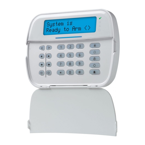
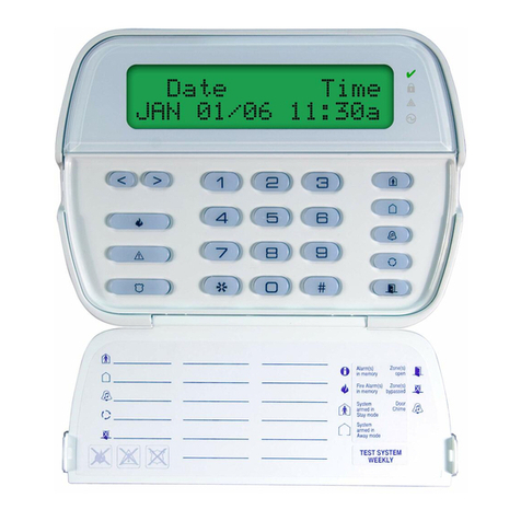
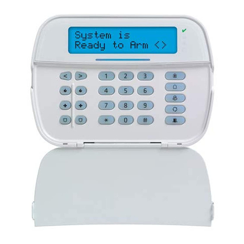
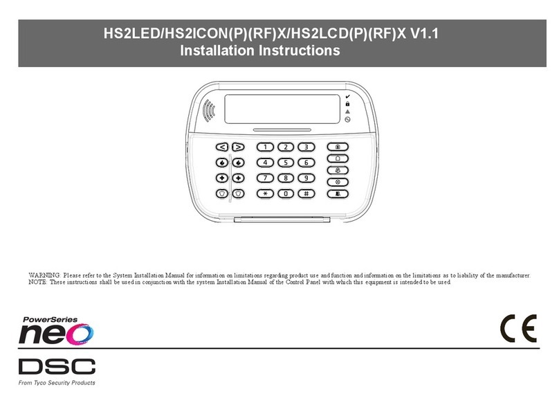
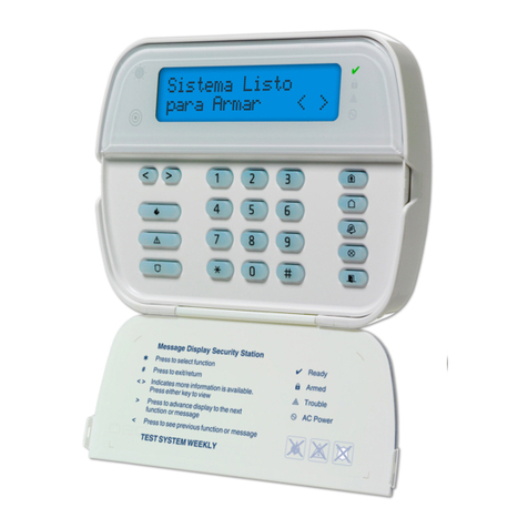
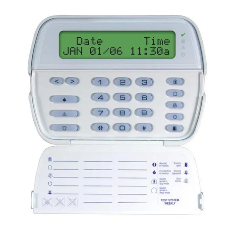
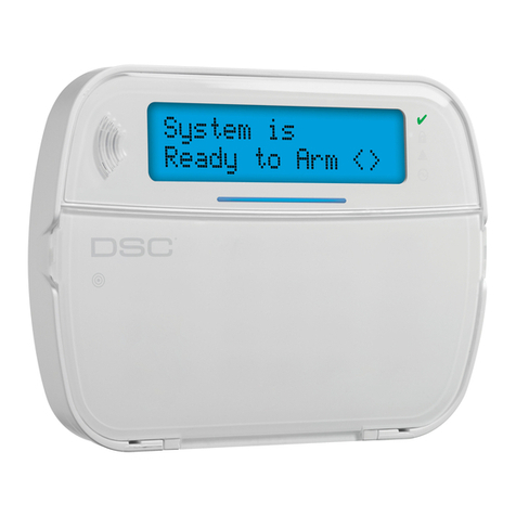
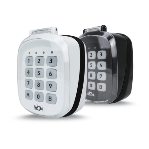
DSC LCD55O1Z User manual

WARNING: Please refer to the System Installation Manual for information on limitations
regarding product use and function and information on the limitations as to liability of the
manufacturer.
ATTENTION: Ce manuel contient des informations sur les restrictions concernant le
fonctionnement et l’utilisation du produit et des informations sur les restrictions en ce qui
concerne la responsabilitédu fabricant. La totalitédu manuel doit être lu attentivement.
ADVERTENCIA: Este manual, contiene información sobre restricciones acerca del
uso y funcionamiento del producto e información sobre las limitaciones, tal como, la re-
sponsabilidad del fabricante. Todo el manual se debe leer cuidadosamente.
Installation Instructions
Instructions d’Installation
Instrucciones de Instalacion
LCD55O1Z
version 2.1
firealarmresources.com

Introduction
Specifications 1
Installation 1
Unpacking ................................................ 1
Mounting 1
Wiring........................................................ 1
Applying Power......................................... 2
Enrolling the Keypad 2
Programming the Keypad 2
Function Key Options ............................... 3
Clock Options ........................................... 3
Alarms Displayed While Armed Option ....3
Emergency Key Options
(Fire, Auxiliary, Panic)............................... 3
Door Chime Options 3
Door Chime on Zone Openings/Closings..4
Door Chime Sounds...................................4
Zone Input/PGM Output Option 4
Programming the PGM Number ................4
Programming Worksheets 5
[✱] Door Chime Sound Programming 6
Introduction
Spécifications 11
Installation 11
Déballage ................................................11
Montage 11
Câblage ...................................................11
Mise sous tension ....................................12
Assignation du clavier 12
Programmation du clavier 13
Options pour les touches de fonction......13
Options pour l’horloge .............................13
Option d’affichage des alarmes
lorsque le système est armé....................14
Options pour les touches d’urgence
(incendie, auxiliaire et panique).............. 14
Options pour le carillon de porte 14
Carillon de porte lors de l’ouverture/la
fermeture des zones ............................... 14
Tonalités pour le carillon ......................... 15
Option pour la borne ‘Z/P’
(Entrée de zone/ sortie PGM) 15
Programmation du numéro de la PGM ... 15
Feuilles de programmation 16
[✱] Programmation de la tonalité
pour le carillon de porte 17
Introducción 22
Especificaciones 22
Instalación
Montaje 22
Conexión ................................................. 22
Aplicar Energía........................................ 23
Registrar el Teclado 23
Programar el Teclado 23
Opciones de las Teclas Funcionales ...... 24
Opciones del Reloj.................................. 24
Opción Alarmas Mostradas
Mientras Armado..................................... 24
Opciones de Teclas de Emergencia
(Fuego, Auxiliar, Pánico)......................... 24
Opciones del Timbre de Puerta 25
Timbre de Puerta en Cierres/Aperturas
de Zonas ................................................ 25
Sonidos del Timbre de Puerta ................ 25
Opción de Entrada de
zona/Salida PGM 26
Programación del número de PGM ....... 26
Hojas de Programación 27
[✱] Programar el Sonido del
Timbre de Puerta 28
Table of Contents / Table des Matieres / Contenido
firealarmresources.com

1
Introduction
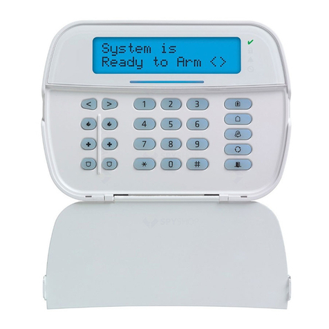
The LCD5501Z keypad presents system
status using an LCD display along with
fixed words/icons and numbers. The key-
pad can be used on security systems
with up to 64 zones. The LCD5501Z is
compatible with the following DSC secu-
rity systems:
• PC580/PC585 • PC5008
• PC1555/PC1565 • PC50XX
• PC1555MX
Specifications
• Connects to control panel via 4-wire
Keybus
• One keypad zone input/PGM output
• Current draw: 35mA (standby) /
125mA (maximum)
• Voltage rating: 12VDC nominal
• Optional tamper version
• Five programmable function keys
• Ready (green), Armed (red) and Trou-
ble (yellow) status lights
Installation
Unpacking
The LCD5501Z package includes the fol-
lowing parts:
• One LCD5501Z keypad
• Four mounting screws
• One keypad inner door label
• One set of Fire, Auxiliary and Panic
key labels
Mounting
You should mount the keypad where it is
accessible to designated points of entry
and exit. Once you have selected a dry
and secure location, perform the follow-
ing steps to mount the keypad.
1. Remove the keypad backplate by
loosening the screw located at the
base of the unit.
2. Secure the keypad backplate to the
wall in the desired location. Use the
screws provided.
3. Before attaching the keypad to its
backplate, complete the keypad wir-
ing as described in the next section.
Wiring
1. Before beginning to wire the unit, en-
sure that all power (AC transformer
and battery) is disconnected from the
control panel.
2. Connect the four Keybus wires from
the control panel (red, black, yellow
and green) to the keypad terminals (R
B Y G). Consult the diagram below:
3. If programmed as an input, you can
connect a device - such as a door
contact - to the ‘Z/P’ terminal of the
LCD5501Z. This eliminates the need to
run wires back to the control panel for
the device. To connect the zone, run
one wire from the device to the ‘Z/P’
terminal and the other wire from the
device to the B (black) terminal. For
F2
F4
F3
F5
F1
AM
✔
TEST SYSTEM WEEKLY
Refer to Instruction Manual for
testing instructions.
X
NOT IN USE NOTIN USE
X
X
NOT IN USE
F1
F2
F3
F4
F5
Red
Blk Yel Grn To Zone Input /
PGM Output
RBYG
Z/P
firealarmresources.com

2
powered devices, run the red wire to
the R (positive) terminal and the black
wire to the B (negative) terminal. When
using end of line supervision, connect
the zone according to one of the con-
figurations outlined in your system’s
Installation Manual.
4. If the ‘Z/P’terminal is programmed as
an output, the output follows the PGM
programmed in Section [8]. A small re-
lay, buzzer or other DC operated de-
vice may be connected between the
positive supply voltage and the ‘Z/P’
terminal (maximum load is 50mA).
Applying Power
Once all wiring is complete, apply power
to the control panel:
1. Connect the battery leads to the battery.
2. Connect the AC transformer.
For more information on control panel
power specifications, see the control
panel Installation Manual.
NOTE: Do not connect the power until all wir-
ing is complete.
Enrolling the Keypad
Once all wiring is complete, you will need
to enter a 2-digit number that tells the
system the partition and slot assignment
of the keypad.
If your system has partitions, you will
need to also assign the keypad to a par-
tition (1st digit).
The slot assignment (2nd digit) tells the
panel which keypad slots are occupied.
The panel can then generate a fault when
a keypad supervisory signal is not
present. There are eight available slots
for keypads. LCD5501Z keypads are al-
ways assigned to slot 1 by default. You
will need to assign each keypad to its
own slot (1 to 8).
Enter the following at each keypad in-
stalled on the system:
1. Enter Installer Programming by press-
ing [*][8][Installer’s Code]
2. Press [000] for Keypad Programming
3. Press [0] for Partition and Slot Assign-
ment
4. Enter a two digit number to specify the
partition and slot assignment.
NOTE: If your system does not have partitions,
enter [1] for the first digit.
1st digit Enter [0] for Global Keypad
Enter [1] for Partition 1 Keypad
Enter [2] for Partition 2 Keypad
Enter [3] for Partition 3 Keypad
Enter [4] for Partition 4 Keypad
Enter [5] for Partition 5 Keypad
Enter [6] for Partition 6 Keypad
Enter [7] for Partition 7 Keypad
Enter [8] for Partition 8 Keypad
2nd digit Enter [1] to [8] for Slot Assignment
5. Press the [#] key twice to exit pro-
gramming.
6. After assigning all keypads, perform a
supervisory reset by entering [*][8][In-
staller’s Code][902]. The panel will
now supervise all assigned keypads
and enrolled modules on the system.
Programming the Keypad
There are several programming options
available for the LCD5501Z keypad.
These are described below. Record all
your programming choices in the pro-
gramming worksheets included in this
manual.
Programming the LCD5501Z is similar to
programming the rest of the system.
When you are in the LCD5501Z program-
ming sections, the keypad will display
which options are turned on along the top
of the display. To turn an option on or off,
press the number corresponding to the
option on the number pad. The numbers
of the options that are currently turned
ON will be displayed.
For example, if options 1 and 2 are on,
the display will look like:
For information on programming the rest
of your security system, please refer to
your system’s Installation Manual.
Function Key Options
The function keys are programed in sec-
tions [1] to [5]. By default, the 5 function
keys on the keypad are programmed as
Stay Arm (03), Away Arm (04), Chime

firealarmresources.com

3
(06), Sensor Reset (14) and Quick Exit
(16). You can change the function of
each key on every keypad. Please see
your system’s Installation Manual for in-
structions on programming the keys, and
a complete list of all the function key op-
tions available for your system.
Clock Options
The LCD5501Z will display the current
time after 35 seconds of no key presses.
To set the correct time and date for the
system, please refer to your system’s In-
struction Manual. You can change how
the keypad displays the time with the fol-
lowing options. To change the clock op-
tions:
1. Enter [*][8][Installer’s code]
2. Enter [000] to go to keypad program-
ming
3. Enter section [6] to go to clock op-
tions.
4. To turn any of the options on or off,
press [1], [2], or [3]:
NOTE: If the Time does not display on keypad
option is selected, make sure that the Keypad
displays time when zones are open option is
also selected.
[1]ON =Time displays on keypad
OFF =Time does not display on keypad
[2]ON = Clock display is in AM/PM for-
mat
(e.g. 08:00 AM)
OFF =Clock display is in 24-hour format
(e.g. 20:00)
[3]ON =Keypad does not display time
when zones are open
OFF =Keypad displays time when zones
are open
5. When you are finished programming
the clock options, press [#] to exit.
Alarms Displayed While Armed Option
You can disable the display of alarms on
the keypad when the system is armed.
The display of alarms is enabled by de-
fault. To disable the display of alarms
when the system is armed, turn off sec-
tion [6], option [5]:
1. Enter [*][8][Installer’s code]
2. Enter [000] to go to keypad program-
ming
3. To turn the display of alarms on or off,
enter section [6].
4. Turn option [5] on or off:
[5]ON = Alarms not displayed while sys-
tem is armed
OFF = Alarms are always displayed
while system is armed
5. When you are finished, press [#] to exit.
Emergency Key Options (Fire, Auxiliary,
Panic)
You can enable or disable the Fire, Aux-
iliary and Panic keys at each keypad.
These keys are enabled by default.
Please see your system’s Installation
Manual for more information on these
keys and their options. To turn any of the
emergency keys on or off on the keypad:
1. Enter [*][8][Installer’s code]
2. Enter [000] to go to keypad program-
ming
3. Enter section [7].
4. To turn the emergency key options on
or off, press [1], [2], or [3]:
[1]ON = Fire key enabled
OFF = Fire key disabled
[2]ON = Auxiliary key enabled
OFF = Auxiliary key disabled
[3]ON = Panic key enabled
OFF = Panic key disabled
5. When you are finished, press [#] to ex-
it.
Door Chime Options
You can program the LCD5501Z keypad
to sound a tone when any zone is opened
or closed. There are two parts to the
LCD5501Z door chime programming:
•Program if the LCD5501Z will chime
when zones are opened and/or
closed.
•Program the type of sound the
LCD5501Z will make when an individ-
ual zone is opened or closed.
For the door chime feature to work, you
will also need to turn on the Door Chime
attribute for each zone that will trigger the
chime. This programming is done in the
control panel software. Refer to your con-
trol panel’s Installation Manual for more
information.
Door Chime on Zone Openings/Closings
You can program each LCD5501Z key-
pad to sound a door chime when zones
firealarmresources.com

4
are opened and/or when they are closed.
By default, LCD5501Z keypads are pro-
grammed to sound door chimes on both
zone openings and closings.
To change the door chime opening/clos-
ing settings, at each LCD5501Z keypad:
1. Enter [*][8][Installer’s code]
2. Enter [000] to go to keypad program-
ming
3. Enter section [6].
4. To turn the options on or off, press [6]
or [7]:
[6] ON =Door Chime Enabled for Zone
Openings
OFF =Door Chime Disabled for Zone
Openings
[7] ON =Door Chime Enabled for Zone
Closings
OFF =Door Chime Disabled for Zone
Closings
5. When you are finished, press [#] to ex-
it.
Door Chime Sounds
You can program the LCD5501Z keypad
to make different door chime sounds for
individual zones, or groups of zones.
Each LCD5501Z keypad can make any
of four door chime sounds for each zone
that triggers the door chime:
•4 quick beeps (default sound)
•‘Bing –Bing’tone
•‘Ding –Dong’tone
•‘Alarm’tone
NOTE: For a zone to be able to trigger the
door chime sound, the Door Chime zone at-
tributemust alsobe enabledin the control pan-
el programming. Please see your control panel
Installation Manual.
To change the door chime sounds:
1. Enter [*][8][Installer’s code].
2. Enter [*] to go to door chime sound
programming.
3. Enter a 2-digit number for the zone
you want to program [01] - [64].
4. Turn one of the following options on by
pressing [1], [2], [3], or [4]:
[1]4 quick beeps (default sound)
[2]‘Bing –Bing’tone
[3]‘Ding –Dong’tone
[4]‘Alarm’tone
NOTE: Make sure that only one of the above
options is turned on. If more than one is on,
the keypad will sound the first option that is
enabled. If none of the options are selected, the
keypad will not make any sound when thezone
is opened or closed.
5. To program the door chime sound for
another zone, repeat steps 3 and 4.
6. When you are finished programming
the door chime sounds, press [#] to
exit.
Zone Input/PGM Output Option
The LCD5501Z ‘Z/P’terminal can be pro-
grammed to support one zone input (de-
fault) or one PGM output. To change this
option:
1. Enter [*][8] [Installer Code].
2. Enter [000] to go to Keypad Program-
ming.
3. Enter section [6].
4. Turn the option on or off by pressing
[8].
If Option 8 is ON, the ‘Z/P’terminal is an
output.
If Option 8 is OFF, the ‘Z/P’terminal is an
input.
Programming the PGM Number
In order to assign a PGM output to the “Z/
P”terminal, a PGM number must be en-
tered. This number has to be one of the
PGM outputs that can be programmed in
the panel.
1. Enter [*][8] [Installer Code].
2. Enter [000] to go to Keypad Program-
ming.
3. Enter Section [8].
4. Enter the 2-digit PGM number (Do Not
enter the PGM Output Option).
firealarmresources.com

5
Programming Worksheets
[000] Keypad Programming
1. Enter [*][8][Installer’s code]
2. Enter [000] to go to keypad program-
ming
[0] Keypad Enrollment
Valid entries are 01-18; e.g. enter [11] for
partition 1, slot 1. Default = 11
1st digit Enter 0 for Global Keypad
Enter [1] for Partition 1 Keypad
Enter [2] for Partition 2 Keypad
Enter [3] for Partition 3 Keypad
Enter [4] for Partition 4 Keypad
Enter [5] for Partition 5 Keypad
Enter [6] for Partition 6 Keypad
Enter [7] for Partition 7 Keypad
Enter [8] for Partition 8 Keypad
2nd digit Enter 1 to 8 for Slot Assignment
S l ot : I________I________I
[1]-[5] Function Key Assignments
[6] LCD5501Z Keypad Options
[7] Emergency Key Options
[1] Key 1 [2] Key 2 [3] Key 3 [4] Key 4 [5] Key 5
Defaults: 03 04 06 14 16
Stay Away Chime Reset Exit
I________I________I I________I________I I________I________I I________I________I I________I________I
Default Option
ON I________I 1ON= Local clock display enabled
OFF = Local clock display disabled
ON I________I 2ON= Local clock displays AM/PM
OFF = Local clock displays 24 hour time
OFF I________I 3ON= Open zones override clock display
OFF = Open zones do not override clock display
OFF I________I 4For Future Use
OFF I________I 5ON= Alarms not displayed while armed
OFF = Alarms always displayed while armed
ON I________I 6ON= Door chime enabled for zone openings
OFF = Door chime disabled for zone openings
ON I________I 7ON= Door chime enabled for zone closings
OFF = Door chime disabled for zone closings
OFF I________I 8ON= “Z/P”terminal is an output
OFF = “Z/P”terminal is an input
Default Option ON OFF
ON I________I 1 [F] key enabled [F] key disabled
ON I________I 2 [A] key enabled [A] key disabled
ON I________I 3 [P] key enabled [P] key disabled
OFF I________I 4-8 For Future Use
firealarmresources.com

6
[8] PGM Terminal
[✱] Door Chime Sound Programming
1. Enter [*][8][Installer’s code][*]
2. Enter 2-digit zone number [01] - [64], then select door chime sound option [1] - [4].
Repeat for each zone that is to sound a chime.
Default
01 I_________I________|PGM Number
Zone Location Options: [1]
4 beeps
(default)
[2]
“bing-
bing”
[3]
“ding-
ding”
[4]
Alarm
Tone
[01] |________________________| I________I I________I I________I I________I
[02] |________________________| I________I I________I I________I I________I
[03] |________________________| I________I I________I I________I I________I
[04] |________________________| I________I I________I I________I I________I
[05] |________________________| I________I I________I I________I I________I
[06] |________________________| I________I I________I I________I I________I
[07] |________________________| I________I I________I I________I I________I
[08] |________________________| I________I I________I I________I I________I
[09] |________________________| I________I I________I I________I I________I
[10] |________________________| I________I I________I I________I I________I
[11] |________________________| I________I I________I I________I I________I
[12] |________________________| I________I I________I I________I I________I
[13] |________________________| I________I I________I I________I I________I
[14] |________________________| I________I I________I I________I I________I
[15] |________________________| I________I I________I I________I I________I
[16] |________________________| I________I I________I I________I I________I
[17] |________________________| I________I I________I I________I I________I
[18] |________________________| I________I I________I I________I I________I
firealarmresources.com

7
[19] |________________________| I________I I________I I________I I________I
[20] |________________________| I________I I________I I________I I________I
[21] |________________________| I________I I________I I________I I________I
[22] |________________________| I________I I________I I________I I________I
[23] |________________________| I________I I________I I________I I________I
[24] |________________________| I________I I________I I________I I________I
[25] |________________________| I________I I________I I________I I________I
[26] |________________________| I________I I________I I________I I________I
[27] |________________________| I________I I________I I________I I________I
[28] |________________________| I________I I________I I________I I________I
[29] |________________________| I________I I________I I________I I________I
[30] |________________________| I________I I________I I________I I________I
[31] |________________________| I________I I________I I________I I________I
[32] |________________________| I________I I________I I________I I________I
[33] |________________________| I________I I________I I________I I________I
[34] |________________________| I________I I________I I________I I________I
[35] |________________________| I________I I________I I________I I________I
[36] |________________________| I________I I________I I________I I________I
[37] |________________________| I________I I________I I________I I________I
[38] |________________________| I________I I________I I________I I________I
[39] |________________________| I________I I________I I________I I________I
[40] |________________________| I________I I________I I________I I________I
[41] |________________________| I________I I________I I________I I________I
[42] |________________________| I________I I________I I________I I________I
[43] |________________________| I________I I________I I________I I________I
[44] |________________________| I________I I________I I________I I________I
firealarmresources.com

8
[45] |________________________| I________I I________I I________I I________I
[46] |________________________| I________I I________I I________I I________I
[47] |________________________| I________I I________I I________I I________I
[48] |________________________| I________I I________I I________I I________I
[49] |________________________| I________I I________I I________I I________I
[50] |________________________| I________I I________I I________I I________I
[51] |________________________| I________I I________I I________I I________I
[52] |________________________| I________I I________I I________I I________I
[53] |________________________| I________I I________I I________I I________I
[54] |________________________| I________I I________I I________I I________I
[55] |________________________| I________I I________I I________I I________I
[56] |________________________| I________I I________I I________I I________I
[57] |________________________| I________I I________I I________I I________I
[58] |________________________| I________I I________I I________I I________I
[59] |________________________| I________I I________I I________I I________I
[60] |________________________| I________I I________I I________I I________I
[61] |________________________| I________I I________I I________I I________I
[62] |________________________| I________I I________I I________I I________I
[63] |________________________| I________I I________I I________I I________I
[64] |________________________| I________I I________I I________I I________I
firealarmresources.com

Limited Warranty
Digital Security Controls Ltd. warrants the original pur-
chaser that for a period of twelve months from the date of
purchase, the product shall be free of defects in materials
and workmanship under normal use. During the warranty
period, Digital Security Controls Ltd. shall, at its option,
repair or replace any defective product upon return of the
product to its factory, at no charge for labour and materi-
als. Any replacement and/or repaired parts are warranted
for the remainder of the original warranty or ninety (90)
days, whichever is longer. The original purchaser must
promptly notify Digital Security Controls Ltd. in writing
that there is defect in material or workmanship, such writ-
ten notice to be received in all events prior to expiration of
the warranty period. There is absolutely no warranty on
software and all software products are sold as a user
license under the terms of the software license agreement
included with the product. The Customer assumes all
responsibility for the proper selection, installation, opera-
tion and maintenance of any products purchased from
DSC. Custom products are only warranted to the extent
that they do not function upon delivery. In such cases,
DSC can replace or credit at its option.
International Warranty
The warranty for international customers is the same as for
any customer within Canada and the United States, with
the exception that Digital Security Controls Ltd. shall not
be responsible for any customs fees, taxes, or VAT that
may be due.
Warranty Procedure
To obtain service under this warranty, please return the
item(s) in question to the point of purchase. All authorized
distributors and dealers have a warranty program. Anyone
returning goods to Digital Security Controls Ltd. must first
obtain an authorization number. Digital Security Controls
Ltd. will not accept any shipment whatsoever for which
prior authorization has not been obtained.
Conditions to Void Warranty
This warranty applies only to defects in parts and work-
manship relating to normal use. It does not cover:
• damage incurred in shipping or handling;
• damage caused by disaster such as fire, flood, wind,
earthquake or lightning;
• damage due to causes beyond the control of Digital
Security Controls Ltd. such as excessive voltage,
mechanical shock or water damage;
• damage caused by unauthorized attachment, alter-
ations, modifications or foreign objects;
• damage caused by peripherals (unless such peripherals
were supplied by Digital Security Controls Ltd.);
• defects caused by failure to provide a suitable installa-
tion environment for the products;
• damage caused by use of the products for purposes
other than those for which it was designed;
• damage from improper maintenance;
• damage arising out of any other abuse, mishandling or
improper application of the products.
Items Not Covered by Warranty
In addition to the items which void the Warranty, the follow-
ing items shall not be covered by Warranty: (i) freight cost
to the repair centre; (ii) products which are not identified
with DSC's product label and lot number or serial number;
(iii) products disassembled or repaired in such a manner as
to adversely affect performance or prevent adequate inspec-
tion or testing to verify any warranty claim. Access cards or
tags returned for replacement under warranty will be cred-
ited or replaced at DSC's option. Products not covered by
this warranty, or otherwise out of warranty due to age, mis-
use, or damage shall be evaluated, and a repair estimate shall
be provided. No repair work will be performed until a valid
purchase order is received from the Customer and a Return
Merchandise Authorisation number (RMA) is issued by
DSC's Customer Service.
Digital Security Controls Ltd.’s liability for failure to
repair the product under this warranty after a reasonable
number of attempts will be limited to a replacement of the
product, as the exclusive remedy for breach of warranty.
Under no circumstances shall Digital Security Controls
Ltd. be liable for any special, incidental, or consequential
damages based upon breach of warranty, breach of con-
tract, negligence, strict liability, or any other legal theory.
Such damages include, but are not limited to, loss of prof-
its, loss of the product or any associated equipment, cost
of capital, cost of substitute or replacement equipment,
facilities or services, down time, purchaser’s time, the
claims of third parties, including customers, and injury to
property. The laws of some jurisdictions limit or do not
allow the disclaimer of consequential damages. If the
laws of such a jurisdiction apply to any claim by or against
DSC, the limitations and disclaimers contained here shall
be to the greatest extent permitted by law. Some states do
not allow the exclusion or limitation of incidental or con-
sequential damages, so that the above may not apply.
Disclaimer of Warranties
This warranty contains the entire warranty and shall be in
lieu of any and all other warranties, whether expressed or
implied (including all implied warranties of merchantabil-
ity or fitness for a particular purpose) and of all other obli-
gations or liabilities on the part of Digital Security
Controls Ltd. Digital Security Controls Ltd. neither
assumes responsibility for nor authorizes any other person
purporting to act on its behalf to modify or to change this
warranty, nor to assume for it any other warranty or liabil-
ity concerning this product.
This disclaimer of warranties and limited warranty are
governed by the laws of the province of Ontario, Canada.
WARNING: Digital Security Controls Ltd. recommends
that the entire system be completely tested on a regular
basis. However, despite frequent testing, and due to, but
not limited to, criminal tampering or electrical disrup-
tion, it is possible for this product to fail to perform as
expected.
Out of Warranty Repairs
Digital Security Controls Ltd. will at its option repair or
replace out-of-warranty products which are returned to its
factory according to the following conditions. Anyone
returning goods to Digital Security Controls Ltd. must first
obtain an authorization number. Digital Security Controls
Ltd. will not accept any shipment whatsoever for which
prior authorization has not been obtained.
Products which Digital Security Controls Ltd. determines
to be repairable will be repaired and returned. A set fee
which Digital Security Controls Ltd. has predetermined
and which may be revised from time to time, will be
charged for each unit repaired.
firealarmresources.com

WARNING Please Read Carefully
Note to Installers
This warning contains vital information. As the only individual
in contact with system users, it is your responsibility to bring
each item in this warning to the attention of the users of this sys-
tem.
System Failures
This system has been carefully designed to be as effective as
possible. There are circumstances, however, involving fire, bur-
glary, or other types of emergencies where it may not provide
protection. Any alarm system of any type may be compromised
deliberately or may fail to operate as expected for a variety of
reasons. Some but not all of these reasons may be:
■ Inadequate Installation
A security system must be installed properly in order to provide
adequate protection. Every installation should be evaluated by a
security professional to ensure that all access points and areas
are covered. Locks and latches on windows and doors must be
secure and operate as intended. Windows, doors, walls, ceilings
and other building materials must be of sufficient strength and
construction to provide the level of protection expected. A
reevaluation must be done during and after any construction
activity. An evaluation by the fire and/or police department is
highly recommended if this service is available.
■Criminal Knowledge
This system contains security features which were known to be
effective at the time of manufacture. It is possible for persons
with criminal intent to develop techniques which reduce the
effectiveness of these features. It is important that a security
system be reviewed periodically to ensure that its features
remain effective and that it be updated or replaced if it is found
that it does not provide the protection expected.
■Access by Intruders
Intruders may enter through an unprotected access point, cir-
cumvent a sensing device, evade detection by moving through
an area of insufficient coverage, disconnect a warning device, or
interfere with or prevent the proper operation of the system.
■Power Failure
Control units, intrusion detectors, smoke detectors and many
other security devices require an adequate power supply for
proper operation. If a device operates from batteries, it is possi-
ble for the batteries to fail. Even if the batteries have not failed,
they must be charged, in good condition and installed correctly.
If a device operates only by AC power, any interruption, how-
ever brief, will render that device inoperative while it does not
have power. Power interruptions of any length are often accom-
panied by voltage fluctuations which may damage electronic
equipment such as a security system. After a power interruption
has occurred, immediately conduct a complete system test to
ensure that the system operates as intended.
■Failure of Replaceable Batteries
This system’s wireless transmitters have been designed to pro-
vide several years of battery life under normal conditions. The
expected battery life is a function of the device environment,
usage and type. Ambient conditions such as high humidity, high
or low temperatures, or large temperature fluctuations may
reduce the expected battery life. While each transmitting device
has a low battery monitor which identifies when the batteries
need to be replaced, this monitor may fail to operate as
expected. Regular testing and maintenance will keep the system
in good operating condition.
■Compromise of Radio Frequency (Wireless) Devices
Signals may not reach the receiver under all circumstances
which could include metal objects placed on or near the radio
path or deliberate jamming or other inadvertent radio signal
interference.
■System Users
A user may not be able to operate a panic or emergency switch
possibly due to permanent or temporary physical disability,
inability to reach the device in time, or unfamiliarity with the
correct operation. It is important that all system users be trained
in the correct operation of the alarm system and that they know
how to respond when the system indicates an alarm.
■Smoke Detectors
Smoke detectors that are a part of this system may not properly
alert occupants of a fire for a number of reasons, some of which
follow. The smoke detectors may have been improperly
installed or positioned. Smoke may not be able to reach the
smoke detectors, such as when the fire is in a chimney, walls or
roofs, or on the other side of closed doors. Smoke detectors may
not detect smoke from fires on another level of the residence or
building.
Every fire is different in the amount of smoke produced and the
rate of burning. Smoke detectors cannot sense all types of fires
equally well. Smoke detectors may not provide timely warning
of fires caused by carelessness or safety hazards such as smok-
ing in bed, violent explosions, escaping gas, improper storage of
flammable materials, overloaded electrical circuits, children
playing with matches or arson.
Even if the smoke detector operates as intended, there may be
circumstances when there is insufficient warning to allow all
occupants to escape in time to avoid injury or death.
■Motion Detectors
Motion detectors can only detect motion within the designated
areas as shown in their respective installation instructions. They
cannot discriminate between intruders and intended occupants.
Motion detectors do not provide volumetric area protection.
They have multiple beams of detection and motion can only be
detected in unobstructed areas covered by these beams. They
cannot detect motion which occurs behind walls, ceilings, floor,
closed doors, glass partitions, glass doors or windows. Any type
of tampering whether intentional or unintentional such as mask-
ing, painting, or spraying of any material on the lenses, mirrors,
windows or any other part of the detection system will impair
its proper operation.
Passive infrared motion detectors operate by sensing changes in
temperature. However their effectiveness can be reduced when
the ambient temperature rises near or above body temperature
or if there are intentional or unintentional sources of heat in or
near the detection area. Some of these heat sources could be
heaters, radiators, stoves, barbeques, fireplaces, sunlight, steam
vents,lighting and so on.
■Warning Devices
Warning devices such as sirens, bells, horns, or strobes may not
warn people or waken someone sleeping if there is an interven-
ing wall or door. If warning devices are located on a different
level of the residence or premise, then it is less likely that the
occupants will be alerted or awakened. Audible warning
devices may be interfered with by other noise sources such as
stereos, radios, televisions, air conditioners or other appliances,
or passing traffic. Audible warning devices, however loud, may
not be heard by a hearing-impaired person.
■Telephone Lines
If telephone lines are used to transmit alarms, they may be out
of service or busy for certain periods of time. Also an intruder
may cut the telephone line or defeat its operation by more
sophisticated means which may be difficult to detect.
■Insufficient Time
There may be circumstances when the system will operate as
intended, yet the occupants will not be protected from the emer-
gency due to their inability to respond to the warnings in a
timely manner. If the system is monitored, the response may not
occur in time to protect the occupants or their belongings.
■Component Failure
Although every effort has been made to make this system as
reliable as possible, the system may fail to function as intended
due to the failure of a component.
■Inadequate Testing
Most problems that would prevent an alarm system from oper-
ating as intended can be found by regular testing and mainte-
nance. The complete system should be tested weekly and
immediately after a break-in, an attempted break-in, a fire, a
storm, an earthquake, an accident, or any kind of construction
activity inside or outside the premises. The testing should
include all sensing devices, keypads, consoles, alarm indicating
devices and any other operational devices that are part of the
system.
■Security and Insurance
Regardless of its capabilities, an alarm system is not a substitute
for property or life insurance. An alarm system also is not a sub-
stitute for property owners, renters, or other occupants to act
prudently to prevent or minimize the harmful effects of an
emergency situation.
firealarmresources.com

11
Introduction
Le clavier LCD5501Z indique les états du
système àl’aide des mots et des chiffres
fixes. qu’il fait apparaître sur son af-
ficheur àcristaux liquides. Ce clavier
peut être utiliséavec des systèmes de
sécuritéprotégeant jusqu’à 64 zones.
Le LCD5501Z est compatible avec les
systèmes de sécuritéDSC suivants :
•PC580/PC585 •PC5008
•PC1555/PC1565 •PC50XX
•PC1555MX
Spécifications
•Raccordement au panneau de
contrôle via le Keybus à4 fils.
•Une entrée de zone et une sortie PGM
•Consommation de courant : 35mA (en
veille) / 85mA (maximum)
•Tension nominale : 12Vc.c.
•Version avec interrupteur
antisabotage optionnelle
•Cinq touches de fonctions
programmables
•Voyants d’état Prêt (vert), Armé
(rouge) et Trouble (jaune)
Installation
Déballage
La boîte du LCD5501Z contient les élé-
ments suivants :
•Un clavier LCD5501Z
•Quatre vis de montage
•Une autocollant pour l’intérieur de la
porte du clavier
•Un ensemble d’autocollants pour les
touches d’alarme d’incendie, d’alarme
auxiliaire et d’alarme de panique.
Montage
Pour le montage du clavier, choisissez
un endroit près du point d’entrée qui est
sec, sécuritaire et accessible. Lorsque
vous avez déterminél’emplacement de
montage, suivez les étapes suivantes :
1. Retirez le partie arrière du clavier en
dévissant la vis située àla base de
l’unité.
2. Àl’aide des vis fournies avec l’unité,
fixez la partie arrière du clavier àl’en-
droit choisi.
3. Avant de fixer le clavier sur sa plaque
arrière, effectuez tout le câblage
décrit dans la rubrique suivante.
Câblage
1. Avant de commencer àcâbler l’unité,
assurez-vous que l’alimentation
(transformateur c.a. et batterie) du
panneau de contrôle est coupée.
2. Raccordez les quatre fils du Keybus
qui proviennent du panneau de con-
trôle (rouge, noir, jaune et vert) sur les
bornes (R, B, Y et G) du clavier. Réfé-
rez-vous au schéma ci-dessous.
AM AM
✔
VÉRIFIEZLE SYSTÈME
CHAQUESEMAINE
Consultezla procédure
à suivre dans votre manuel
X
PASUTILISÉ
X
PASUTILISÉ
X
PASUTILISÉ
F2
F4
F3
F5
F1
F1
F2
F3
F4
F5
R = Rouge
B = Noir
Y = Jaune
G = Vert L'entree de zone
Sortie de PGM
Z/P
RBYG
firealarmresources.com

12
3. Si la borne ‘Z/P’du LCD5501Z est pro-
grammée en tant qu’entrée, vous pou-
vez raccorder un dispositif sur cette
borne, comme par exemple un con-
tact de porte. Ceci est un bon moyen
d’économiser du temps et du câblage
en évitant d’avoir àinstaller un câble
entre le panneau de contrôle et le con-
tact de la porte qui se trouve àproxim-
itédu clavier. Pour raccorder la zone,
installez un câble entre le dispositif et
le clavier et raccordez un des fils prov-
enant du dispositif sur la borne ‘Z/P’
du clavier et un autre sur la borne B. Si
le dispositif doit être alimenté, raccor-
dez le fil rouge àla borne R (positif) et
le fil noir àla borne B (négatif).
Si une résistance de fin de ligne doit
être utilisée, raccordez la zone en
vous conformant àl’une des configu-
rations décrites dans le manuel d’in-
stallation du système.
4. Si la borne ‘Z/P’est programmée en
tant que sortie, celle-ci suit la pro-
grammation de la sortie PGM pro-
grammée dans la section [8]. Un petit
relais, un avertisseur sonore ou un au-
tre dispositif qui fonctionne sous ten-
sion c.c. peut être raccordéentre la
borne d’alimentation positive et la
borne ‘Z/P’(consommation maximale
de courant de 50mA).
Mise sous tension
Une fois le câblage complété, mettez le
panneau de contrôle sous tension.
1. Raccordez les câbles de batterie àla
batterie.
2. Branchez le transformateur CA.
Pour de plus amples informations sur les
spécifications d’alimentation du panneau
de contrôle, référez-vous au manuel d’in-
stallation du panneau de contrôle.
NOTE: Ne mettez pas le panneau de contrôle
sous tension avant que tout le câblage ait été
complété.
Assignation du clavier
Une fois le câblage complété, vous de-
vez entrer un numéro à2 chiffres qui sert
àindiquer au système la partition et l’em-
placement de mémoire qui sont assignés
au clavier.
Si votre système est diviséen partitions,
vous devez également assigner le clavier
àune partition (1er chiffre).
L’assignation de l’emplacement de mé-
moire (2echiffre) permet d’indiquer au
panneau quels sont les emplacements de
mémoire dédiés aux claviers qui sont occu-
pés. Le panneau peut ainsi générer une
panne de supervion lorsqu’il ne reçoit pas de
signal de présence du clavier. Il y a huit em-
placements de mémoire pour les claviers.
Les claviers LCD5501Z sont toujours as-
signés par défaut àl’emplacement de mé-
moire 1. Vous devez assigner chaque clavier
àun emplacement de mémoire (1 à8).
Entrez ce qui suit pour chacun des cla-
viers qui est installédans le sytème.
1. Accédez au mode de programmation
de l’installateur en entrant [*][8][code
de l’installateur].
2. Entrez [000] pour accéder àla pro-
grammation du clavier.
3. Appuyez sur [0] pour accéder àl’assig-
nation de la partition et de l’emplace-
ment de mémoire du clavier.
4. Entrez le numéro àdeux chiffres qui
représente la partition et l’emplace-
ment de mémoire.
NOTE: Si votre système n’est pas divisé en
partitions, entrez [1] comme premier chiffre.
1er chiffreEntrez [0] pour un clavier global
Entrez [1] pour assigner le clavier àla
partition 1
Entrez [2] pour assigner le clavier àla
partition 2
Entrez [3] pour assigner le clavier àla
partition 3
Entrez [4] pour assigner le clavier àla
partition 4
Entrez [5] pour assigner le clavier àla
partition 5
Entrez [6] pour assigner le clavier àla
partition 6
Entrez [7] pour assigner le clavier àla
partition 7
Entrez [8] pour assigner le clavier àla
partition 8
firealarmresources.com

13
2echiffre Entrez un chiffre de 1 à8 pour
indiquer l’emplacement du
clavier.
5. Pour quitter le mode de programma-
tion, appuyez deux fois sur [#].
6. Une fois tous les claviers assignés,
exécutez une réinitialisation de la su-
pervision en entrant [*][8][code de
l’installateur][902]. Le panneau super-
visera dorénavant tous les claviers et
les modules qui ont étéassignés dans
le système.
Programmation du clavier
Plusieurs options de programmation sont
disponibles pour le clavier LCD5501Z.
Ces options sont décrites ci-dessous. In-
scrivez tous vos choix de programmation
sur les feuilles de programmation qui se
trouvent àla fin de ce manuel.
La programmation du LCD5501Z est
similaire àcelle du reste du système.
Lorsque vous êtes dans le mode de pro-
grammation du LCD5501Z, l’afficheur du
clavier vous indiquent quelles sont les
options qui sont activées. Pour activer ou
désactiver une option, appuyez sur la
touche numérique qui correspond au
numéro de l’option. Les numéros d’op-
tions qui apparaissent dans le haut de
l’afficheur correspondent aux options qui
sont activées.
Par exemple, si les options 1 et 2 sont ac-
tivées, l’afficheur aura l’air de ceci :
Pour de plus amples informations sur la
façon de programmer le reste du sys-
tème, veuillez vous référer au manuel
d’installation du système.
Options pour les touches de fonction
La programmation des touches de fonc-
tion s’effectue dans les sections [1] à[5].
Par défaut, les cinq touches de fonction
du clavier sont programmées comme
suit: armement en mode Àdomicile (03),
armement en mode Absent (04), Carillon
(06), Rétablissement des détecteurs (14)
et Sortie rapide (16). Vous pouvez modi-
fier la fonction de chacune des touches
de chacun des claviers. Pour de plus
amples informations sur la programma-
tion des touches de fonction et pour
obtenir une liste complète de toutes les
options pour les touches de fonctions qui
sont disponibles pour votre système,
veuillez vous référer au manuel d’installa-
tion.
Options pour l’horloge
Lorsque aucune touche n’a étéenfoncée
depuis plus de 35 secondes, le
LCD5501Z affiche l’heure. Pour régler
l’heure et la date du système, veuillez
vous référer au manuel d’instructions du
système. Vous pouvez modifier la
manière dont le clavier affiche l’heure à
l’aide des options suivantes. Pour mod-
ifier les options de l’horloge:
1. Entrez [*][8][code de l’installateur]
2. Entrez [000] pour accéder au mode
de programmation du clavier.
3. Entrez [6] pour accéder àla section
de programmation des options de
l’horloge.
4. Pour activer ou désactiver les options,
appuyez sur [1], [2], ou [3].
NOTE: Si l’heure ne s’affiche pas sur le clavier
et que l’option “heure affichée sur le clavier”
est sélectionnée, assurez-vous que l’option “Le
clavier affiche l’heure lorsque des zones sont
ouvertes” est également sélectionnée.
[1] ACTIVÉE=L’heure est affichée sur le
clavier
DÉSACTIVÉE=L’heure n’est pas af-
fichée sur le clavier
[2] ACTIVÉE= Heure affichée dans le for-
mat AM/PM (par ex.: 08:00 AM).
DÉSACTIVÉE=Heure affichée dans le
format 24 heures (par ex.: 20:00)
[3] ACTIVÉE=Le clavier n’affiche pas
l’heure lorsque des zones sont
ouvertes
DÉSACTIVÉE=Le clavier affiche
l’heure lorsque des zones sont
ouvertes
5. Une fois la programmation des op-
tions de l’horloge complétée, appuyez
sur [#] pour quitter.
Option d’affichage des alarmes lorsque le
système est armé
Vous pouvez empêcher l’affichage des
alarmes sur le clavier lorsque le système
firealarmresources.com

14
est armé. Par défaut, les alarmes sont af-
fichées lorsque le système est armé.
Pour empêcher l’affichage des alarmes
lorsque le système est armé, activez l’op-
tion [5] de la section [6].
1. Entrez [*][8][code de l’installateur]
2. Entrez [000] pour accéder àla pro-
grammation du clavier.
3. Pour permettre ou empêcher l’affichage
des alarmes, accédez àla section [6].
4. Activez ou désactivez l’option [5].
[5]ACTIVÉE= Les alarmes ne sont pas
affichées lorsque le système est armé.
DÉSACTIVÉE= Les alarmes sont toujo-
urs affichées lorsque le système est
armé.
5. Lorsque vous avez terminé, appuyez sur
[#] pour quitter.
Options pour les touches d’urgence
(incendie, auxiliaire et panique)
Vous pouvez activer ou désactiver les
touches d’urgence d’incendie, d’ur-
gence auxiliaire et de panique de
chaque clavier. Par défaut, ces touches
sont activées. Pour de plus amples infor-
mations sur ces touches et sur leurs op-
tions, veuillez vous référer au manuel
d’installation du système. Pour activer ou
désactiver l’une ou l’autre des touches
d’urgence du clavier :
1. Entrez [*][8][code de l’installateur]
2. Entrez [000] pour accéder àla pro-
grammation du clavier
3. Accédez àla section [7].
4. Pour activer ou désactiver les touches
d’urgence, appuyez sur [1], [2] ou [3].
[1] ACTIVÉE= Touche incendie activée
DÉSACTIVÉE= Touche incendie dés-
activée
[2] ACTIVÉE= Touche auxiliaire activée
DÉSACTIVÉE= Touche auxiliaire dés-
activée
[3] ACTIVÉE= Touche de panique ac-
tivée
DÉSACTIVÉE= Touche de panique
désactivée
5. lorsque vous avez terminé, appuyez sur
[#] pour quitter.
Options pour le carillon de porte
Vous pouvez programmer le LCD5501Z
de façon àce qu’il émette une tonalité
chaque fois qu’une zone est ouverte ou
fermée, et ce, pour chacune des zones.
La programmation du carillon de porte
du LCD5501Z se fait en deux parties :
•Vous devez sélectionner si le carillon
du LCD5501Z doit être déclenchélors
des ouvertures ou des fermetures des
zones ou dans les deux cas.
•Vous devez sélectionnez pour chacune
des zones la tonalitéque le LCD5501Z
fera entendre lorsque la zone
déclenchera le carillon de porte.
Afin qu’une zone puisse déclencher le
carillon de porte, vous devez également
sélectionner l’attribut “Carillon”de cette
zone. La programmation des attributs
des zones se fait dans le logiciel du pan-
neau de contrôle. Pour de plus amples
informations, veuillez vous référer au
manuel d’installation du panneau de con-
trôle.
Carillon de porte lors de l’ouverture/la
fermeture des zones
Vous pouvez programmer chaque cla-
vier LCD5501Z pour qu’il émette une to-
nalitécarillon lors de l’ouverture ou de la
fermeture des zones ou dans les deux
cas. Par défaut, les claviers LCD5501Z
sont programmés pour émettre une to-
nalitécarillon lors de l’ouverture et de la
fermeture des zones.
Pour modifier le réglage du carillon de
port de chaque clavier LCD5501Z:
1. Entrez [*][8][code de l’installateur]
2. Entrez [000] pour accéder àla pro-
grammation du clavier.
3. Accédez àla section [6].
4. Pour activer ou désactiver les options,
appuyez sur [6] ou [7].
[6] ACTIVÉE= Carillon de porte activé
llors de l’ouverture des zones
DÉSACTIVÉE= Carillon de porte dés-
activélors de l’ouverture des zones
[7] ACTIVÉE=Carillon de porte activélors
de la fermeture des zones
DÉSACTIVÉE= Carillon de porte dés-
activélors de la fermeture des zones
firealarmresources.com

15
5. lorsque vous avez terminé, appuyez sur
[#] pour quitter.
Tonalités pour le carillon
Vous pouvez sélectionner, parmi quatre
tonalités différentes, la tonalitéqui sera
émise par le clavier LCD5501Z pour cha-
cune des zones ou chacun des groupes
de zones qui déclencheront le carillon.
Ces tonalités sont les suivantes :
•4 bips rapides (tonalitépar défaut)
•”Bing –Bing”
•”Ding –Dong”
•Tonalitéd’alarme
NOTE: Pour qu’une zone puisse être en
mesure de déclencher le carillon de porte,
l’attribut “Carillon” de cette zone doit être
sélectionné dans la programmation du
panneau de contrôle . Veuillez vous référer au
manuel d’installation du panneau de contrôle.
Pour modifier la tonalitédu carillon de
porte d’une zone :
1. Entrez [*][8][code de l’installateur].
2. Entrez [*] pour accéder àla program-
mation de la tonalitédu carillon de
porte.
3. Entrez les 2 chiffres du numéro de la
zone [01] à[64] pour laquelle vous dé-
sirez programmer la tonalité.
4. Activez une des options suivantes en
appuyant sur la touche [1], [2], [3] ou
[4] qui correspond àla tonalitéchoi-
sie.
[1]4 bips rapides (par défaut)
[2]“Bing –Bing”
[3]“Ding –Dong”
[4]Tonalitéd’alarme
NOTE: Assurez-vous qu’une seule de ces
options est activée. Si plus d’une option est
activée, le clavier émettra la tonalité qui
correspondà lapremière option quiestactivée.
Si aucune de ces options n’est activée, le
clavier n’émettra aucune tonalité lors des
ouvertures et des fermetures de la zone.
5. Pour programmer la tonalitédu car-
illon de porte d’une autre zone,
répétez les étapes 3 et 4.
6. Lorsque vous avez terminéla pro-
grammation des tonalités de carillon
de porte, appuyez sur [#] pour quitter.
Option pour la borne ‘Z/P’
(Entrée de zone/ sortie PGM)
La borne ‘Z/P’du clavier LCD5501Z peut
être programmée en tant qu’entrée de
zone (par défaut) ou de sortie PGM. Pour
modifier cette option :
1. Entrez [*][8] [code de l’installateur].
2. Entrez [000] pour accéder àla pro-
grammation du clavier.
3. Accédez àla section [6].
4. Activez ou désactivez l’option en ap-
puyant sur [8].
Si l’option 8 est ACTIVÉE, la borne ‘Z/P’du
clavier est une sortie.
Si l’option 8 est DÉSACTIVÉE, la borne ‘Z/
P’est une entrée.
Programmation du numéro de la PGM
Afin que la borne ‘Z/P’puisse être utilisée
en tant que sortie PGM, un numéro de
sortie PGM doit être entré. Ce numéro
doit correspondre àun numéro de PGM
qui peut être programmédans le pan-
neau.
1. Entrez [*][8] [code de l’installateur].
2. Entrez [000] pour accéder àla pro-
grammation du clavier.
3. Accédez àla section [8].
4. Entrez les 2 chiffres du numéro de la
sortie PGM (N’entrez pas le numéro
d’option de la sortie PGM).
firealarmresources.com

16
Feuilles de programmation
[000] Programmation du clavier
1. Entrez [*][8][code de l’installateur]
2. Entrez [000] pour accéder àla pro-
gramamtion du clavier.
[0] Assignation du clavier
Les entrées valides sont de 01 à18. Par
exemple, entrez [11] pour la partition 1,
emplacement de mémoire 1.
Par défaut = 11
1er chiffreEntrez 0 pour un clavier Global
Entrez [1] pour assigner le clavier àla
partition 1
Entrez [2] pour assigner le clavier àla
partition 2
Entrez [3] pour assigner le clavier àla
partition 3
Entrez [4] pour assigner le clavier àla
partition 4
Entrez [5] pour assigner le clavier àla
partition 5
Entrez [6] pour assigner le clavier àla
partition 6
Entrez [7] pour assigner le clavier àla
partition 7
Entrez [8] pour assigner le clavier àla
partition 8
2e chiffre Entrez le numéro de 1 à8 qui
correspond àl’emplacement du clavier
Emplacement : I________I________I
[1] à [5] Assignation des touches de fonction
[6] Options pour le clavier LCD5501Z
[1] Touche 1 [2] Touche 2 [3] Touche 3 [4] Touche 4 [5] Touche 5
Par défaut : 03 04 06 14 16
À domicile Absent Carillon Rétablissement
des détecteurs Sortie rapide
I________I________I I________I________I I________I________I I________I________I I________I________I
Par défaut Option
ACTIVÉEI________I 1ACTIVÉE= Affichage de l’heure activé
DÉSACTIVÉE= Affichage de l’heure désactivé
ACTIVÉEI________I 2ACTIVÉE= Heure affichéen mode AM/PM
DÉSACTIVÉE= Heure affichée en mode 24 h
DÉSACTIVÉEI________I 3
ACTIVÉE= Les zones ouvertes remplacent l’affichage
de l’heure
DÉSACTIVÉE= Les zones ouvertes ne remplacent pas
l’affichage de l’heure
DÉSACTIVÉEI________I 4Pour usage futur
DÉSACTIVÉEI________I 5
ACTIVÉE = Les alarmes ne sont pas affichées lorsque
le système est armé
DÉSACTIVÉE= Les alarmes sont toujours affichées lor-
sque le système est armé
ACTIVÉEI________I 6ACTIVÉE = Door chime enabled for zone openings
DÉSACTIVÉE= Door chime disabled for zone openings
ACTIVÉEI________I 7
ACTIVÉE = Carillon de porte activélors des ouvertures
des zones
DÉSACTIVÉE= Carillon de porte désactivélors des fer-
metures de zones
DÉSACTIVÉEI________I 8ACTIVÉE= La borne “Z/P”est une sortie
DÉSACTIVÉE= La borne “Z/P”est une entrée
firealarmresources.com

17
[7] Options pour les touches d’urgence
[8] Borne PGM
[✱] Programmation de la tonalité pour le carillon de porte
1. Entrez [*][8][code de l’installateur][*]
2. Entrez les 2 chiffres du numéro de la
zone [01] à[64] que vous désirez pro-
grammer et sélectionnez ensuite une
des options de tonalité[1] à[4].
Répétez cette procédure pour cha-
cune des zones qui doit déclencher le
carillon de porte.
Default Option ON OFF
ON I________I 1 [F] key enabled [F] key disabled
ON I________I 2 [A] key enabled [A] key disabled
ON I________I 3 [P] key enabled [P] key disabled
OFF I________I 4-8 For Future Use
Par défaut
01 I_________I________| Numéro de PGM
Zone Emplacement Options: [1]
4 bips
(défaut)
[2]
“bing-
bing”
[3]
“ding-
dong”
[4]
Tonalité
d’alarme
[01] |________________________| I________I I________I I________I I________I
[02] |________________________| I________I I________I I________I I________I
[03] |________________________| I________I I________I I________I I________I
[04] |________________________| I________I I________I I________I I________I
[05] |________________________| I________I I________I I________I I________I
[06] |________________________| I________I I________I I________I I________I
[07] |________________________| I________I I________I I________I I________I
[08] |________________________| I________I I________I I________I I________I
[09] |________________________| I________I I________I I________I I________I
[10] |________________________| I________I I________I I________I I________I
[11] |________________________| I________I I________I I________I I________I
[12] |________________________| I________I I________I I________I I________I
[13] |________________________| I________I I________I I________I I________I
firealarmresources.com

18
[14] |________________________| I________I I________I I________I I________I
[15] |________________________| I________I I________I I________I I________I
[16] |________________________| I________I I________I I________I I________I
[17] |________________________| I________I I________I I________I I________I
[18] |________________________| I________I I________I I________I I________I
[19] |________________________| I________I I________I I________I I________I
[20] |________________________| I________I I________I I________I I________I
[21] |________________________| I________I I________I I________I I________I
[22] |________________________| I________I I________I I________I I________I
[23] |________________________| I________I I________I I________I I________I
[24] |________________________| I________I I________I I________I I________I
[25] |________________________| I________I I________I I________I I________I
[26] |________________________| I________I I________I I________I I________I
[27] |________________________| I________I I________I I________I I________I
[28] |________________________| I________I I________I I________I I________I
[29] |________________________| I________I I________I I________I I________I
[30] |________________________| I________I I________I I________I I________I
[31] |________________________| I________I I________I I________I I________I
[32] |________________________| I________I I________I I________I I________I
[33] |________________________| I________I I________I I________I I________I
[34] |________________________| I________I I________I I________I I________I
[35] |________________________| I________I I________I I________I I________I
[36] |________________________| I________I I________I I________I I________I
[37] |________________________| I________I I________I I________I I________I
[38] |________________________| I________I I________I I________I I________I
[39] |________________________| I________I I________I I________I I________I
firealarmresources.com
Table of contents
Languages:
Other DSC Keypad manuals

DSC
DSC HS2LED Series User manual

DSC
DSC RF55O1-433 User manual

DSC
DSC PowerSeries Neo User manual

DSC
DSC LCD-600 User manual

DSC
DSC PC 4010 User manual

DSC
DSC PC1500 User manual

DSC
DSC PowerSeries LCD5511 User manual

DSC
DSC PowerSeries Neo HS2LCDWF User manual

DSC
DSC PK5 Series User manual

DSC
DSC PC5532Z User manual