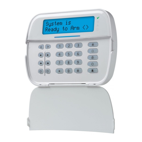
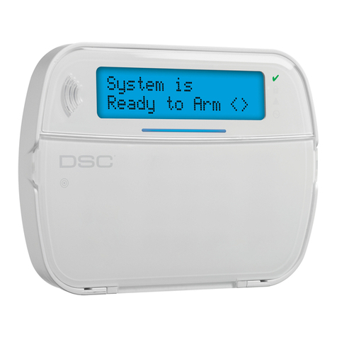
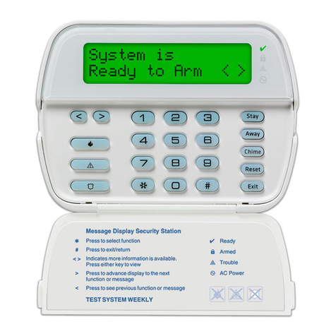
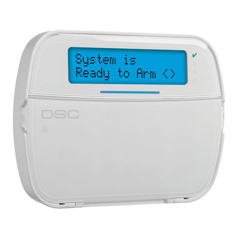
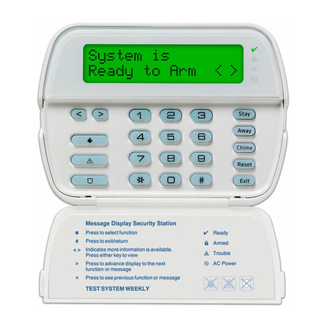
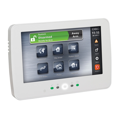
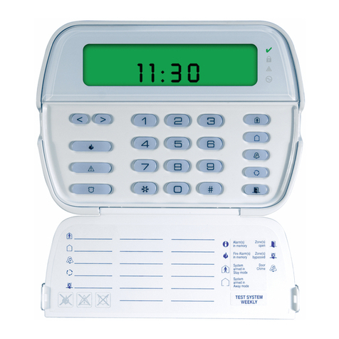
DSC PK5 Series User manual

English, Français, Nederlands, Italiano
WARNING:
Please refer to the System Installation Manual for information on limitations regarding product use and functionand information on the limitations as to liability of the manufacturer.
NOTE:
These instructions shall be used in conjunction with the system Installation Manual of the Control Panel with which this equipment is intended to be used.
ATTENTION:
Ce manuel contient des informations sur les restrictions concernant le fonctionnement et l’utilisation du produit et des informations sur les restrictions en ce qui concerne la responsabilité du fabricant. La totalité du manuel doit être lu
attentivement.
NOTE:
Ce manuel doit être utilisé en conjonction avec le Manuel d'installation du Panneau de contrôle.
WAARSCHUWING:
Raadpleeg de installatiehandleiding van het systeem voor informatie over beperkingen m.b.t. productgebruik en functie en informatie over de beperkingen m.b.t. aansprakelijkheid van de fabrikant.
OPMERKING:
Deze instructies dienen te worden gebruikt in combinatie met de installatiehandleidingvan het systeem van de centrale waarmee deze apparatuur gebruikt wordt.
ATTENZIONE:
Fare riferimento al manuale di installazione del sistema per avere informazioni sui limiti riguardanti l’uso e il funzionamento del prodotto, nonché sui limiti di responsabilità del produttore.
NOTA:
Le presenti istruzioni devono essere impiegate in combinazione con il manuale d’installazione del sistema della centrale di controllo con il quale si intende utilizzare l’apparecchiatura.
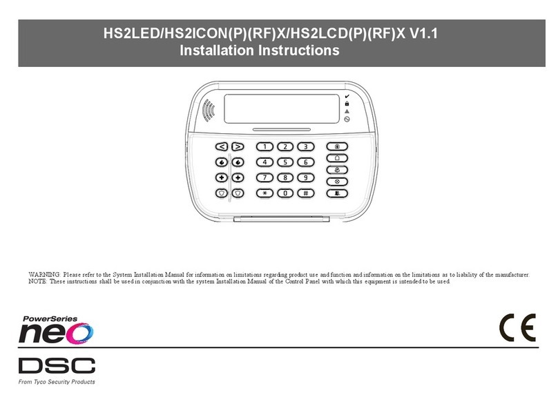
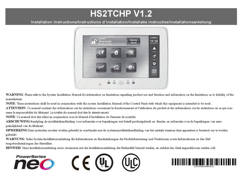
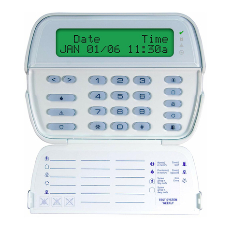
PK55XX/RFK55XX v1.2
Installation Instructions, Instructions d’Installation, Installatiehandleiding, Istruzioni per l’installazione
123
456
78
0
*#
9
RFK5500
PK5500
123
456
78
0
*#
9
RFK5501
PK5501
123
456
78
0
*#
9
RFK5508
PK5508
123
456
78
0
*#
9
RFK5516
PK5516
29007799R001
firealarmresources.com

The PK55XX\RFK55XX keypads can be used on security systems with
up to 64 zones. These keypads are compatible with the latest version
of the folllowing DSC security systems:
The RFK55XX keypads combine a wireless receiver with the respective
PK55XX keypad.
Specifications
• Temperature range: -10°C to +55°C (14°F to 131°F), Temperature
range for UL/ULC: 0°C to +49°C (32°F to 120°F)
• Humidity (MAX): 93%R.H.
• Plastic enclosure protection degree: IP30, IK04
• Voltage rating: 12VDC nominal
• Connects to control panel via 4-wire Keybus
• 1 keypad zone input/PGM output*
• PK55XX Current draw: 50mA (standby)/125mA (maximum)
• RFK55XX Current draw: 75mA (standby)/135mA (maximum)
• Wall mount tamper
• 5 programmable function keys
• Ready (Green LED), Armed (Red LED), Trouble (Yellow LED), AC
(Green LED)
• Low temperature sensor
• Frequency: 433.92MHz (RFK55XX-433 )/868MHz (RFK55XX-868)
• Up to 32 wireless zones (RFK55XX Only)
NOTE: * Zone not to be programmed as Fire type or 24h type.
Unpacking
The Power keypad package includes the following parts:
Mounting
You should mount the keypad where it is accessible to designated
points of entry and exit. Once you have selected a dry and secure loca-
tion, perform the following steps to mount the keypad.
Disassemble Keypad
1. Insert a flat head screwdriver into theprovided slot (first of two)
2. Move screwdriver toward the back plastic and lift as in the below
diagram. This will unhook one side of the front plastic.
3. Repeat step # 1 and 2 on the second provided slot to disconnect
the front plastic and allow access for wiring.
Mount and Wire Keypad
1. Secure Keypad to wall using mounting holes. Use all 4 screws provided
unless mounting on a single gang box.
2. Place keypad into hooks on the backplate and swing down to engage.
3. Run wire through wiring slot or knockouts. Connect Keybus and PGM/Zone
wiring to keypad. Place tamper switch into tamper hole on backplate.
4. Remove keypad from hooks. Place keypad into backplate, ensure the wire
is pushed back into the wall as much as possible. Route the wire inside
the keypad ensuring high components are avoided. Snap the front assem-
bly closed, ensuring that there is no pressure to the keypad from the wire
below.
NOTE: If any tension found between the front keypad assembly and wiring,
please open the keypad reroute the wire and close again. Repeat these
steps until the keypad is closed properly.
Wiring
1. Before wiring the unit, ensure that all
power (AC transformer and battery) is dis-
connected from the control panel.
2. Connect the four Keybus wires from the con-
trol panel (red, black, yellow and green) to
the keypad terminals. Refer to diagram:
3. If programmed as an input, you can con-
nect a device - such as a door contact - to
the ‘P/Z’ terminal of the keypad. This eliminates the need to run wires
back to the control panel for the device. To connect thezone, run one wire
from the device to the ‘P/Z’ terminal and the other wire from the device to
the B (black) terminal. For powered devices, run the red wire to the R
(positive) terminal and the black wire to the B (negative) terminal. When
using end of line supervision, connect the zone according to one of the
configurations outlined in your system’s Installation Manual.
4. If the ‘P/Z’ terminal is programmed as an output, the output follows the
PGM programmed in Section [080]. A small relay, buzzer or other DC
English
Installation Instructions
•PC580 •PC585 •PC1555MX •PC1565
•PC1616 •PC1832 •PC1864 •PC5005
•PC5008 •PC5010 •PC5015 •PC5016
•PC5020
•One Power keypad •Keypad inner door labels
•Four mounting screws •1 tamper switch
•2 end-of-line resistors •Installation Instructions
1
2
3
Knock Out
Knock Out
Knock Out
Wiring Slot
Tamper
Hooks
Swing
to engage
Press to Snap
1. 2.
3. 4.
Ta m p e r
Hooks
PK55XX/RFK55XX
RED
BLK
YEL
GRN
To zone or
PGM output
firealarmresources.com

operated device may be connected between the positive supply voltage
and the ‘P/Z’ terminal (maximum load is 50mA).
NOTE: For UL Residential Fire Installations useat least one additional DSC
compatible keypad in conjunction with an RFK55XX keypad or install the
RFK55XX keypads within 3 feet from the control unit and mechanically pro-
tect the keybus wires
Applying Power
Once all wiring is complete, and the equipment is secured to the building
structure with at least two screws apply power to the control panel:
1. Connect the battery leads to the battery.
2. Connect the AC transformer.
For more information on control panel power specifications, see the control
panel Installation Manual.
Programming the Keypad
There are several programming
options available for the keypad.
These are described below. Pro-
gramming the keypad is similar
to programming the rest of the
system. When you are inthe key-
pad programming sections, the
keypad will display which
options are turned on along the
top of the display. To turn an
option on or off, press the num-
ber corresponding to the option
on the number pad. The numbers of the options that are currently turned
ON will be displayed. For example, if options 1 and 4 are on, the display
will look like diagram shown on the different keypad displays.
For information on programming the rest of your security system, please
refer to your system’s Installation Manual.
Broadcasting LCD Labels
All LCD programming is done per keypad. If more than one LCD keypad is
present on the system, labels programmed at one keypad can be broadcast
to all other LCD keypads.Perform the following procedure in order to broad-
cast labels:
Step 1 - Program one LCD keypad completely.
Step 2 - Make sure all LCD keypads are connected to the Keybus.
Step 3 - Enter keypad programming by pressing [][8][Installer
Code][], then enter section [998] at the keypad that was programmed.
The keypad will now broadcast all the information programmed to all the
other LCD keypads on the system.
Step 4 - When the keypad is finished press the [#] key to exit.
NOTE: LCD Label broadcast from this keypad is only compatible
with PC1616/PC1832/PC1864 control panels and other PK5500/
RFK5500 keypads.
Language Programming
(PK5500\RFK5500 Only)
Hold (<>) keys for 2 seconds to enter language programming, scroll to
the desired language and Press [] to select.
NOTE: If section [077] option 4 is OFF, language programming
can only be performed while in installers programming.
Enrolling the Keypad
The keypad will need to be assigned to a partition and slot if supervision or
keypad zones are being used. Keypad assignments and keypad option pro-
gramming must be done at each keypad individually.
The 1st digit of keypad assignment is used to determine partition assign-
ment (1 to 8). If partitioning is not used, enter [1]. For Global Keypads,
enter [0].
NOTE: LED and ICON keypads cannot be programmed as Global Keypads
The 2nd digit of keypad assignment is used to determine slot assignment
for keypad supervision. Each keypad will be assigned a different slot num-
ber from 1 to 8. PK5500 and RFK5500 LCD keypads come defaulted in slot
8. If LCD keypads are used one LCD keypad must remain in slot 8.
NOTE: The RFK55XX enrolls as two modules:
Light 1 = keypad section of the RFK55XX
Light 17 = receiver section of the RFK55XX
NOTE: Deleting all wireless devices from the RFK55XX or defaulting the
RFK55XX will causea supervisory fault.
Enter the following at each keypad installed on the system:
1. Enter Installer Programming by pressing [][8][Installer’s Code]
2. Press [000] for Keypad Programming
3. Press [0] for Partition and Slot Assignment
4. Enter the 1st digit (0 to 8 for partition assignment)
5. Enter the 2nd digit (1 to 8 for slot assignment supervision)
6. Press the [#] key twice to exit programming.
7. After assigning all keypads, perform a supervisory reset by entering
[][8][Installer’s Code][902] and wait for 60 seconds.
8. Press the [#] key to exit programming after 60 seconds.
Programming Labels
(PK5500\RFK5500 Only)
1. Enter keypad programming by pressing [][8][Installer Code][]. Enter
the 3-digit section number for the label to be programmed.
2. Use the arrow keys (<>) to move the underline bar underneath the let-
ter to be changed.
3. Press the number keys [1] to [9] corresponding to the letter you require.
The first time you press the number the first letter will appear. Pressing the
number key again will display the next letter.
4. When the required letter or number is displayed use the arrow keys
(<>) to scroll to the next letter.
5. When you are finished programming the Zone Label, press the [] key,
scroll to “Save,” then press [].
6. Continue from Step 2 until all Labels are programmed.
ASCII Characters
Changing Brightness/Contrast
LCD Keypads
1. Press [][6][Master code].
2. Use the [<][>] keys to scroll to either Brightness Control or Contrast Control.
3. Press [] to select the setting you want to adjust.
4. a) ‘Brightness Control’: There are multiple backlighting levels. Use the [<][>]
keys to scroll to the desired level.
b) ‘Contrast Control’: There are 10 different display contrast levels. Use the
[<][>] keys to scroll to the desiredcontrast level.
5. To exit, press [#].
LED/ICON Keypads
1. Press [][6][Master Code].
2. Use the [>] key to move through the 4 different backlighting levels.
3. The level is automatically saved when you press [#] to exit.
Changing the Buzzer Level
LCD Keypads
1. Press [][6][Master Code].
2. Use the [<][>] keys toscroll to Buzzer Control.
3. There are 21 different levels, use the [<][>] keys to scroll to the desired level.
4. To exit, press [#].
LED/ICON Keypads
1. Press [][6][Master Code].
2. Use the [<] key to move through the 21 different buzzer levels.
3. The level is automatically saved when you press [#] to exit.
Broadcasting Door Chime
All door chime programming is done per keypad. If more than one keypad is
present on the system, door chime programmed at one keypad can be broad-
cast to all other keypads. Perform the following procedure in order to broadcast
door chime:
Step 1 - Program one keypad completely.
Step 2 - Make sure all keypads are connected to the Keybus.
Step 3 - Enter keypad programming by pressing [][8][Installer Code][], then
enter section [994] at the keypad that wasprogrammed. The keypad will
now broadcast all the door chime information programmed to all the
other keypads on the system.
Step 4 - When the keypad is finished press the [#] key to exit.
41
Toggle Option
1 _ _ 4 _ _ _ _
[1] - A, B, C, 1 [4] - J, K, L, 4 [7] - S, T, U, 7 [0] - Space
[2] - D, E, F, 2 [5] - M, N, O, 5 [8] - V, W, X, 8
[3] - G, H, I, 3 [6] - P, Q, R, 6 [9] - Y, Z, 9,0
firealarmresources.com

LIMITED WARRANTY
Digital Security Controls (DSC) warrants that for a period of 12 months from
the date of purchase, the product shall be free of defects in materials and work-
manship under normal use and thatin fulfilment of any breach of such warranty,
DSC shall, at its option, repair or replace the defective equipment upon return of
the equipment to its repair depot. This warranty applies only to defects in parts
and workmanship and not to damage incurred in shipping or handling, or dam-
age due to causes beyond the control of Digital Security Controls such as light-
ning, excessive voltage, mechanical shock, water damage, or damage arising
out of abuse, alteration or improper application of the equipment. The foregoing
warranty shall apply only to the original buyer, and is and shall be in lieu of any
and all other warranties, whether expressed or implied and of all other obliga-
tions or liabilities on the part of Digital Security Controls. Digital Security Con-
trols neither assumes responsibility for, nor authorizes any other person
purporting to act on its behalf to modify or to change this warranty, nor to
assume for it any other warranty or liability concerning this product. In no
event shall Digital Security Controls be liable for any direct, indirect or conse-
quential damages, loss of anticipated profits, loss of time or any other losses
incurred by the buyer in connection with the purchase, installation or operation
or failure of this product. WARNING: Digital Security Controls recommends
that the entire system be completely tested on a regular basis. However, despite
frequent testing, and due to, but not limited to, criminal tampering or electrical
disruption, it is possible for this product to fail to perform as expected. IMPOR-
TANT INFORMATION: Changes/modifications not expressly approved by
DSC could void the user’s authority to operate this equipment.
IMPORTANT - READ CAREFULLY: DSC Software purchased with
or without Products and Components is copyrighted and is purchased
under the following license terms:
• This End-User License Agreement (“EULA”) is a legal agreement between
You (the company, individual or entity who acquired the Software and any
related Hardware) and Digital Security Controls, a division of Tyco Safety
Products Canada Ltd. (“DSC”), the manufacturer of the integrated security
systems and the developer of the software and any related products or compo-
nents (“HARDWARE”) which You acquired.
• If the DSC software product (“SOFTWARE PRODUCT” or “SOFTWARE”)
is intended to be accompanied by HARDWARE, and is NOT accompanied by
new HARDWARE, You may not use, copy or install the SOFTWARE
PRODUCT. The SOFTWARE PRODUCT includes computer software, and
may include associated media, printed materials, and “online” or electronic
documentation.
• Any software provided along with the Software Product that is associated with
a separate end-user license agreement is licensed to You under the terms of
that license agreement.
• By installing, copying, downloading, storing, accessing or otherwise using the
Software Product, You agree unconditionally to be bound by the terms of this
EULA, even if this EULA is deemed to be a modification of any previous
arrangement or contract. If You do not agree to the terms of this EULA, DSC
is unwilling to license the Software Product to You, and You have no right to
use it.
SOFTWARE PRODUCT LICENSE
The SOFTWARE PRODUCT is protected by copyright laws and international
copyright treaties, as well as other intellectual property laws and treaties. The
SOFTWARE PRODUCT is licensed, not sold.
1. GRANT OF LICENSE This EULA grants You the following rights:
(a) Software Installation and Use - For each license You acquire, You may
have only one copy of the SOFTWARE PRODUCT installed.
(b) Storage/Network Use - The SOFTWARE PRODUCT may not be
installed, accessed, displayed, run, shared or used concurrently on or from
different computers, including a workstation, terminal or other digital electronic
device (“Device”). In other words, if You have several workstations, You will
have to acquire a license for each workstation where the SOFTWARE will be
used.
(c) Backup Copy - You may make back-up copies of the SOFTWARE
PRODUCT, but You may only have one copy per license installed at any given
time. You may use the back-up copy solely for archival purposes. Except as
expressly provided in this EULA, You may not otherwise make copies of the
SOFTWARE PRODUCT, including the printed materials accompanying the
SOFTWARE.
2. DESCRIPTION OF OTHER RIGHTS AND LIMITATIONS
(a) Limitations on Reverse Engineering, Decompilation and Disassembly
- You may not reverse engineer, decompile, or disassemble the SOFTWARE
PRODUCT, except and only to the extent that such activity is expressly
permitted by applicable law notwithstanding this limitation. You may not make
any changes or modifications to the Software, without the written permission of
an officer of DSC. You may not remove any proprietary notices, marks or labels
from the Software Product. You shall institute reasonable measures to ensure
compliance with the terms and conditions of this EULA.
(b) Separation of Components - The Software Product is licensed as a
single product. Its component parts may not be separated for use on more than
one HARDWARE unit.
(c) Single INTEGRATED PRODUCT - If You acquired this SOFTWARE
with HARDWARE, then the SOFTWARE PRODUCT is licensed with the
HARDWARE as a single integrated product. In this case, the SOFTWARE
PRODUCT may only be used with the HARDWARE as set forth in this
EULA..
(d) Rental - You may not rent, lease or lend the SOFTWARE PRODUCT.
You may not make it available to others or post it on a server or web site.
(e) Software Product Transfer - You may transfer all of Your rights under
this EULA only as part of a permanent sale or transfer of the HARDWARE,
provided You retain no copies, You transfer all of the SOFTWARE
PRODUCT (including all component parts, the media and printed materials,
any upgrades and this EULA), and provided the recipient agrees to the terms of
this EULA. If the SOFTWARE PRODUCT is an upgrade, any transfer must
also include all prior versions of the SOFTWARE PRODUCT.
(f) Termination - Without prejudice to any other rights, DSC may terminate
this EULA if You fail to comply with the terms and conditions of this EULA. In
such event, You must destroy all copies of the SOFTWARE PRODUCT and all
of its component parts.
(g) Trademarks - This EULA does not grant You any rights in connection
with any trademarks or service marks of DSC or its suppliers.
3. COPYRIGHT - All title and intellectual property rights in and to the
SOFTWARE PRODUCT (including but not limited to any images,
photographs, and text incorporated into the SOFTWARE PRODUCT), the
accompanying printed materials, and any copies of the SOFTWARE
PRODUCT, are owned by DSC or its suppliers. You may not copy the printed
materials accompanying the SOFTWARE PRODUCT. All title and intellectual
property rights in and to the content which may be accessed through use of the
SOFTWARE PRODUCT are the property of the respective content owner and
may be protected by applicable copyright or other intellectual property laws and
treaties. This EULA grants You no rights to use such content. All rights not
expressly granted under this EULA are reserved by DSC and its suppliers.
4. EXPORT RESTRICTIONS - You agree that You will not export or
re-export the SOFTWARE PRODUCT to any country, person, or entity subject
to Canadian export restrictions.
5. CHOICE OF LAW - This Software License Agreement is governed by the
laws of the Province of Ontario, Canada.
6. ARBITRATION - All disputes arising in connection with this Agreement
shall be determined by final and binding arbitration in accordance with the
Arbitration Act, and the parties agree to be bound by the arbitrator’s decision.
The place of arbitration shall be Toronto, Canada, and the language of the
arbitration shall be English.
7. LIMITED WARRANTY
(a) NO WARRANTY - DSC PROVIDES THE SOFTWARE “AS IS”
WITHOUT WARRANTY. DSC DOES NOT WARRANT THAT THE
SOFTWARE WILL MEET YOUR REQUIREMENTS OR THAT
OPERATION OF THE SOFTWARE WILL BE UNINTERRUPTED OR
ERROR-FREE.
(b) CHANGES IN OPERATING ENVIRONMENT - DSC shall not be
responsible for problems caused by changes in the operating characteristics of
the HARDWARE, or for problems in the interaction of the SOFTWARE
PRODUCT with non-DSC-SOFTWARE or HARDWARE PRODUCTS.
(c) LIMITATION OF LIABILITY; WARRANTY REFLECTS
ALLOCATION OF RISK - IN ANY EVENT, IF ANY STATUTE
IMPLIES WARRANTIES OR
CONDITIONS NOT STATED IN THIS
LICENSE AGREEMENT, DSC’S ENTIRE LIABILITY UNDER ANY
PROVISION OF THIS LICENSE AGREEMENT SHALL BE LIMITED TO
THE GREATER OF THE AMOUNT ACTUALLY PAID BY YOU TO
LICENSE THE SOFTWARE PRODUCT AND FIVE CANADIAN
DOLLARS (CAD$5.00). BECAUSE SOME JURISDICTIONS DO NOT
ALLOW THE EXCLUSION OR LIMITATION OF LIABILITY FOR
CONSEQUENTIAL OR INCIDENTAL DAMAGES, THE ABOVE
LIMITATION MAY NOT APPLY TO YOU.
(d) DISCLAIMER OF WARRANTIES - THIS WARRANTY
CONTAINS THE ENTIRE WARRANTY AND SHALL BE IN LIEU OF
ANY AND ALL OTHER WARRANTIES, WHETHER EXPRESSED OR
IMPLIED (INCLUDING ALL IMPLIED WARRANTIES OF
MERCHANTABILITY OR FITNESS FOR A PARTICULAR PURPOSE)
AND OF ALL OTHER OBLIGATIONS OR LIABILITIES ON THE PART
OF DSC. DSC MAKES NO OTHER WARRANTIES. DSC NEITHER
ASSUMES NOR AUTHORIZES ANY OTHER PERSON PURPORTING
TO ACT ON ITS BEHALF TO MODIFY OR TO CHANGE THIS
WARRANTY, NOR TO ASSUME FOR IT ANY OTHER WARRANTY OR
LIABILITY CONCERNING THIS SOFTWARE PRODUCT.
(e) EXCLUSIVE REMEDY AND LIMITATION OF WARRANTY -
UNDER NO CIRCUMSTANCES SHALL DSC BE LIABLE FOR ANY
SPECIAL, INCIDENTAL, CONSEQUENTIAL OR INDIRECT DAMAGES
BASED UPON BREACH OF WARRANTY, BREACH OF CONTRACT,
NEGLIGENCE, STRICT LIABILITY, OR ANY OTHER LEGAL
THEORY. SUCH DAMAGES INCLUDE, BUT ARE NOT LIMITED TO,
LOSS OF PROFITS, LOSS OF THE SOFTWARE PRODUCT OR ANY
ASSOCIATED EQUIPMENT, COST OF CAPITAL, COST OF
SUBSTITUTE OR REPLACEMENT EQUIPMENT, FACILITIES OR
SERVICES, DOWN TIME, PURCHASERS TIME, THE CLAIMS OF
THIRD PARTIES, INCLUDING CUSTOMERS, AND INJURY TO
PROPERTY. WARNING: DSC recommends that the entire system be
completely tested on a regular basis. However, despite frequent testing,
and due to, but not limited to, criminal tampering or electrical disruption,
it is possible for this SOFTWARE PRODUCT to fail to perform as
expected.
FCC Compliance Statement - CAUTION: Changes or modifications
not expressly approved by DSC could void your authority to use this
equipment.
This equipment generates and uses radio frequency energy and if not installed
and used properly, in strict accordance with the manufacturer’s instructions,
may cause interference to radio and television reception. It has been type tested
and found to comply with the limits for Class B device in accordance with the
specifications in Subpart “B” of Part 15 of FCC Rules, which are designed to
provide reasonable protection against such interference in any residential instal-
lation. However, there is no guarantee that interference will not occur in a partic-
ular installation. If this equipment does cause interference to television or radio
reception, which can be determined by turning the equipment off and on, the
user is encouraged to try to correct the interference by one or more of the fol-
lowing measures:
• Re-orient the receiving antenna
• Relocate the alarm control with respect to the receiver
• Move the alarm control away from the receiver
• Connect the alarm control into a different outlet so that alarm control and
receiver are on different circuits.
If necessary, the user should consult the dealer or an experienced radio/televi-
sion technician for additional suggestions. The user may find the following
booklet prepared by the FCC helpful: “How to Identify and Resolve Radio/
Television Interference Problems”. This booklet is available from the U.S. Gov-
ernment Printing Office, Washington, D.C. 20402, Stock # 004-000-00345-4.
Operating Instructions shall be made available to the user.
©2010 Digital Security Controls, Toronto, Canada • www.dsc.com • Tech Support: 1-800-387-3630 (Canada, US), 905-760-3036 Printed in Canada
firealarmresources.com

Keypad Enrollment
Enter keypad programming by pressing [][8][Installer’s Code][000].
[0] Partition / Slot Assignment
[1]-[5] Function Key Assignment
Keypad Function Keys
Refer to your system installation manual for a complete list of all function key options available for your system.
Keypad Programming
Enter keypad programming by pressing [][8][Installer Code][]
[001]-[064] Zone Label 1 to 64 (PK5500\RFK5500 Only)
ex. For Zone 1 enter section [001], for Zone 2 enter section [002] etc. Default: “Zone 1” - “Zone 64”
[065] Fire Alarm Label (28 Characters) (PK5500\RFK5500 Only)
Default:“Fire Zone”
[066] Fail to Arm Event Message (PK5500\RFK5500 Only)
Default: “System Has Failed to Arm”
[067] Alarm When Armed Event Message (PK5500\RFK5500 Only)
Default: “Alarm Occurred While Armed < >”
[071] First User Display Mask
[072] Second User Display Mask
[073] Download LCD Message Duration (PK5500\RFK5500 Only)
Default: 003 I_____I_____I_____I (Valid entries are 000-255), 000=Unlimited Message Disp.This
number represents the number of times the Downloaded message is cleared by pressing any key while the
message is up after timeout).
Digit Option Valid Range Default
1st Partition Assignment (0=Global Keypad) 0 to 8 1 I_____I
2nd Slot Assignment 1 to 8 LED,ICON=1/LCD=8 I_____I
Function Key Button Valid Range Default Function
[1] Function Key 1 Assignment 00 to 32 03 Stay Arm I_____I_____I
[2] Function Key 2 Assignment 00 to 32 04 Away Arm I_____I_____I
[3] Function Key 3 Assignment 00 to 32 06 Chime On/Off I_____I_____I
[4] Function Key 4 Assignment 00 to 32 14 Sensor Reset I_____I_____I
[5] Function Key 5 Assignment 00 to 32 16 Quick Exit I_____I_____I
[00] - Null [08] - Bypass Mode [16] - Quick Exit [26] - Time & Date Program
[01] - Partition 1 Select [09] - Trouble Display [17] - Activate Stay/Away [27] - Partition 3 Select
[02] - Partition 2 Select [10] - Alarm Memory [18] - *Global Away Arm [28] - Partition 4 Select
[03] - Stay Arm [11] - User Programming [19] - Command Output 3 [29] - Partition 5 Select
[04] - Away Arm [12] - User Functions [21] - Command Output 4 [30] - Partition 6 Select
[05] - No Entry Arm [13] - Command Output 1 [22] - *Global Disarming [31] - Partition 7 Select
[06] - Chime On/Off [14] - Command Output 2 [23] - Bypass Recall [32] - Partition 8 Select
[07] - System Test [15] - *Global Stay Arm [24] - Bypass Group Recall [33] - Local PGM Activate
*Available only on the PC1616/PC1832/PC1864 version 4.2 or higher.
Section Zone Label
[001] to [064] 1 to 64 I_____I_____I_____I_____I_____I_____I_____I_____I_____I_____I_____I_____I_____I_____I
I_____I_____I_____I_____I_____I_____I_____I_____I_____I_____I_____I_____I_____I_____I
[065] I_____I_____I_____I_____I_____I_____I_____I_____I_____I_____I_____I_____I_____I_____I
I_____I_____I_____I_____I_____I_____I_____I_____I_____I_____I_____I_____I_____I_____I
[066] I_____I_____I_____I_____I_____I_____I_____I_____I_____I_____I_____I_____I_____I_____I_____I_____I
I_____I_____I_____I_____I_____I_____I_____I_____I_____I_____I_____I_____I_____I_____I_____I_____I
[067] I_____I_____I_____I_____I_____I_____I_____I_____I_____I_____I_____I_____I_____I_____I_____I_____I
I_____I_____I_____I_____I_____I_____I_____I_____I_____I_____I_____I_____I_____I_____I_____I_____I
Default Option ON OFF
ON I____I 1 Hold [P]anic Key prompt ON Hold [P]anic Key prompt OFF
ON I____I 2 Auto-arm Control/Time prompt ON Auto-arm Control/Time prompt OFF
ON I____I 3 Quick Arm prompt ON Quick Arm prompt OFF
ON I____I 4 Interior Arm prompt ON Interior Arm prompt OFF
OFF I____I 5 Quick Exit prompt ON Quick Exit prompt OFF
OFF I____I 6 Thermostat Control prompt ON Thermostat Control prompt OFF
OFF I____I 7 ACK All Trouble Prompt ON ACK All Trouble Prompt OFF
OFF I____I 8 Music Input prompt ON Music Input prompt OFF
Default Option ON OFF
ON I____I 1 User-initiated Call-up prompt ON User-initiated Call-up prompt OFF
OFF I____I 2ForFutureUse
OFF I____I 3 Walk Test prompt ON Walk Test prompt OFF
ON I____I 4 Command Output#1 prompt ON Command Output#1 prompt OFF
ON I____I 5 Command Output#2 prompt ON Command Output#2 prompt OFF
OFF I____I 6 Command Output#3 prompt ON Command Output#3 prompt OFF
OFF I____I 7 Command Output#4 prompt ON Command Output#4 prompt OFF
OFF I____I 8ForFutureUse
firealarmresources.com

[074] Key Options
[076] First Keypad Options
[077] Second Keypad Options
[080] PGM Terminal 1
Default: 01 I_______I _______I 1-14 Follow PGM Output Number, 15 Local PGM Pulse , 16 Local PGM Toggle
[082] Local PGM Output Pulse Activation Time
Default: 00 I_______I _______I Minutes (Valid Range 00-99)
Default: 05 I_______I _______I Seconds (Valid Range 00-99)
[101]-[108] Partition Labels (PK5500\RFK5500 Only)
ex. For Partition 1 enter section [101], for Partition 2 enter section [102] etc.
NOTE: Partition 1 Label is also used as the System Label
[120]-[151] Command Output Labels (PK5500\RFK5500 Only)
Default: “Command_O/P_1” - “Command_O/P_4”
[201]-[264] Door Chime Sound Programming
You can program the keypad to makeup to four different door chime sounds for individual zones.
ex. For Zone 1 enter section [201], for Zone 2 enter section [202] etc.
[994][] Initiate Global Keypad Chime Broadcast
[995][] Reset Keypad Options to Factory Default
[996][] Label Default (PK5500\RFK5500 Only)
[997] View Software Version (PK5500\RFK5500 Only)
[998][] Initiate Global Label Broadcast (PK5500\RFK5500 Only)
[999][] Reset Keypad EEPROM to Factory Defaults
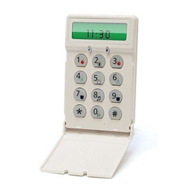
Keypad Display Symbols
Default Option ON OFF
ON I____I 1 [F]ire Key Enabled [F]ire Key Disabled
ON I____I 2 [A]uxiliary Key Enabled [A]uxiliary Key Disabled
ON I____I 3 [P]anic Key Enabled [P]anic Key Disabled
OFF I____I 4-8 For Future Use
Default Option ON OFF
ON I____I 1 Display Code when Programming Display “Xs” when Programming
ON I____I 2 Local Clock Display ON Local Clock Display OFF
OFF I____I 3 Local Clock Displays 24-hr Time Local Clock Displays AM/PM
ON I____I 4 Auto Alarm Memory Scroll Enabled Auto Alarm Memory Scroll Disabled
OFF I____I 5 Local Display of Temperature ON Local Display of Temperature OFF
ON I____I 6 Bypass Options prompt ON Bypass Options prompt OFF
OFF I____I 7ForFutureUse
OFF I____I 8 Auto-Scroll Open Zones ON Auto-Scroll Open Zones OFF
Default Option ON OFF
ON I____I 1 Chime Enabled for Zone Openings Chime Disabled for Zone Openings
ON I____I 2 Chime Enabled for Zone Closings Chime Disabled for Zone Closings
OFF I____I 3 5th Terminal is Keypad PGM Output 5th Terminal is Keypad Zone Input
ON I____I 4 LanguageSelection Enabled LanguageSelection Disabled
OFF I____I 5 Power LED Enabled Power LED Disabled
ON I____I 6 Power LED indicates AC present Power LED indicates AC absent
ON I____I 7 Alarms always Displayed When Armed Alarms not Displayed When Armed
OFF I____I 8 Low Temperature Warning Enabled Low Temperature Warning Disabled
Section Partition Label
[101] to [108] 1 to 8 I_____I_____I_____I_____I_____I_____I_____I_____I_____I_____I_____I_____I_____I_____I
I_____I_____I_____I_____I_____I_____I_____I_____I_____I_____I_____I_____I_____I_____I
For Partition 1 Command O/P 1 to 4 enter [120] to [123] For Partition 5 Command O/P 1 to 4 enter [136] to [139]
For Partition 2 Command O/P 1 to 4 enter [124] to [127] For Partition 6 Command O/P 1 to 4 enter [140] to [143]
For Partition 3 Command O/P 1 to 4 enter [128] to [131] For Partition 7 Command O/P 1 to 4 enter [144] to [147]
For Partition 4 Command O/P 1 to 4 enter [132] to [135] For Partition 8 Command O/P 1 to 4 enter [148] to [151]
Section Part Cmd.
Output Label
[120]-[151]1to8 1to4 I_____I_____I_____I_____I_____I_____I_____I_____I_____I_____I_____I_____I_____I_____I
I_____I_____I_____I_____I_____I_____I_____I_____I_____I_____I_____I_____I_____I_____I
Default Option ON OFF
ON I____I 1 6 Beeps Disabled
OFF I____I 2 “Bing-Bing” Sound Disabled
OFF I____I 3 “Ding-Dong” Sound Disabled
OFF I____I 4AlarmTone Disabled
OFF I____I 5-8 For Future Use
8Bypass – Indicates that thereare zones automatically or
manually bypassed.
9For Future Use
10 Arm Mode – Indicatesthe mode the panel is armed in.
Stay – Indicates that the panel is armed in the Stay
Mode. It will turn on at the beginning of the Exit
Delay
1Fire – Indicates that there are fire alarms in memory.
2Memory – Indicates that there are alarms in memory. Away – Indicates that the panel is armed in the Away
Mode. It will turn on at the beginning of the Exit
Delay
3Ready Light (green) – If the Ready light is on, the system
is ready for arming.
4Armed Light (red) – If the Armed light is on, thesystem
has been armed successfully. 11 Chime – This icon turns on when Door Chime is enabled on
the system and will turn off when Door Chime is disabled.
5System Trouble – Indicates that a system trouble is active.
12 Open – When zones are opened, this icon will turn on, and
7 segment displays 1 and2 will scroll through the open
zones.
6AC – Indicates that AC is present at the main panel.
7Program – Indicates that the system is in Installer’s Pro-
gramming, or the keypad is busy.
12
3
4
5
6
7
8
12 9
10
1112 7
8
firealarmresources.com

Wireless Integration
(RFK55XX Only)
Compatible Wireless Devices (RFK55XX Only)
The RFK55XX can receive signals from the following devices:
Downloading
The RFK55XX product has an integrated wireless receiver. When down-
loading to this keypad, please select the RF5132 v5.2 file. DLS2002
must be used in order to have the capability of downloading to this key-
pad.
Testing Wireless Devices
1. Temporarily put the wireless devices in the places you want to mount
them.
2. At a system keypad, enter [][8][Installer Code].
3. Enter programming section [904], then enter the 2-digit zone number.
NOTE: If global placement test is enabled (Section [90], option 8
ON) enter [01] to test all zones.
4. Activate the device being tested until a result is displayed on the key-
pad or sounded by the keypad or bell
While in placement test the Ready and Armed LEDs are used to indicate
the reception of a valid signal from a wireless device. The Green (Ready)
LED indicates that a transmission was received from a device that is
enrolled on the system. The Red (Armed) LED indicates that a transmis-
sion was received from a device that is not enrolled on the system. The
corresponding LED will flash once per transmission.
Activate the device until you get 3 good results in a row. Wait 10 sec-
onds between each test on the same device. You may mount wireless
devices where results were good.
Devices indicating a bad result must be moved to another location. You
may only have to move the device a few inchesto correct a bad result.
NOTE: Do not mount any device where a “bad” test result was
indicated.
Testing Portable Device Reception
To test portable devices (e.g., WS49X9) press the button(s) at several
different points in the installation, to confirm the coverage area. If these
devices do not operate from all points in the installation, you will need
to move the RFK55XX.
Replacing Wireless Device
Batteries
1. Remove the cover of the device from its backplate. This creates a
tamper condition on the zone.
2. Refer to the battery installation instructions on the Installation Sheet
of each component. Be sure to note the proper orientation of the
batteries as you install them.
3. When the fresh batteries are in place, re-attach the cover to the
backplate. The tamper is restored and the zone sends a battery
trouble restoral signal to the receiver. The battery trouble is now
clear and the device should function normally.
NOTE: When batteries in one device need to be replaced, the bat-
teries in all devices should be replaced at the same time.
Troubleshooting
1. When I enter the 2-digit zone number when adding a wireless
device, the keypad gives me a long beep.
• You cannot enter ESNs unless the RFK55XX is properly connected to the
Keybus.
2. I have entered the ESN for the device but when I violate the device,
the zone does not show open on the keypad.
Check the following:
• Ensure the ESN has been entered correctly
• Ensure that the zone is enabled for the partition (if partition program-
ming is used).
• Ensure that the wireless zone is not assigned to a zone used by
PC5108 modules, an on-board zone or a keypad zone.
• Ensure that the zone is programmed for something other than “Null
Operation” and that the wireless zone attribute is turned on.
3. When I try a module placement test I get no result or “Bad” results.
Check the following:
• Verify that you are testing the correct zone
• Verify that the device is in range of the RFK55XX. Try testing the device
in the same room as the receiver.
• Confirm that the RFK55XX is properly connected to the Keybus.
• Check that you are testing the zone correctly. Refer to the instructions
that came with the zone.
• Check that the batteries are working and installed correctly.
• Look for large metal objects that may be preventing the signal from
reaching the RFK55XX.
• The device must be located where consistent “Good” results are
obtained. If several devices show “Bad” results, or if panic pendants
and wireless keys operate inconsistently, move the receiver.
4. The LED on the motion detector does not turn on when I walk in front
of the unit.
• The LED on the motion detector is for walk test purposes only. See your
WS4904(P) Instruction Sheet for walk test instructions.
This Class B digital apparatus complies with Canadian ICES-003.
Cet appareil numérique de la classe B est conforme à la norme NMB-
003 du Canada.
IC:160A-RFK55XX4
The term IC before the radio certification number signifies that the
Industry Canada technical specifications were met.
EN50131-1 Grade2/Class II
• WLS912L-433 Glass Break Detector • WS4945 Mini Door/Window Contact
• WLS914-433 Pet Immune PIR • WS4965 Tri-Zone Contact
• WS4904(P)/8904(P) Pet Immune • WS4969 Wireless Keys
• WS4916/8916 Smoke Detector • WS4975/8975 Door/Window Contact
• WS4926 Smoke Detector • WS4985/8985 Flood Detector
• WS4938 Panic Button • WS8965 Tri-zone Door/Window Contact
• WS4939/8939 Wireless Key • WS4913/8913 CO Detector*
*Requires PC1616/1832/1864 V4.3 or higher
Result LED/ICON Keypad LCD Keypad Bell/Buzzer
Good Light 1 ON Steady Good 1Beep/Squawk
Bad Light 3 ON Steady Bad 3 Beeps/Squawks
+HUHE\ '6& GHFODUHV WKDW WKLV GHYLFH LV LQ FRPSOLDQFH ZLWK WKH HVVHQWLDO
UHTXLUHPHQWVDQGRWKHUUHOHYDQWSURYLVLRQVRI'LUHFWLYH(&
7KH FRPSOHWH 577( 'HFODUDWLRQ RI &RQIRUPLW\ FDQ EH IRXQG DW
KWWSZZZGVFFRPOLVWLQJVBLQGH[DVS[
&=( '6& MDNR Y¿UREFH SURKODģXMH ŀH WHQWR Y¿UREHN MH Y VRXODGX VH YģHPL
UHOHYDQWQ¯PLSRŀDGDYN\VPÝUQLFH(&
'$1'6&HUNO¨UHUKHUYHGDWGHQQHNRPSRQHQWHQRYHUKROGHUDOOHYLNWLJHNUDYVDPW
DQGUHEHVWHPPHOVHUJLWWLGLUHNWLY(&
'87 +LHUELM YHUNODDUW '6& GDW GLW WRHVWHO LQ RYHUHHQVWHPPLQJ LV PHW GH HLVHQ HQ
EHSDOLQJHQYDQULFKWOLMQ(&
),1'6&YDNXXWWDDODLWWHHQW¦\WW¦Y¦QGLUHNWLLYLQ(&ROHQQDLVHWYDDWLPXNVHW
)5( 3DU OD SU«VHQWH '6& G«FODUH TXH FH GLVSRVLWLI HVW FRQIRUPH DX[ H[LJHQFHV
HVVHQWLHOOHVHWDXWUHVVWLSXODWLRQVSHUWLQHQWHVGHOD'LUHFWLYH(&
*(5+LHUGXUFKHUNO¦UW'6&GD¡GLHVHV*HU¦WGHQHUIRUGHUOLFKHQ%HGLQJXQJHQXQG
9RUUDXVHW]XQJHQGHU5LFKWOLQLH(&HQWVSULFKW
*5(˂˜˞˱ˬ˲˭˞ˮ˹˪˱ˬ˯ ˤ '6& ˡˤ˨˻˪ˢ˦˹˱˦˞˲˱˛ ˤ ˰˲˰˧ˢ˲˛ ˢ˜˪˞˦˰˺˩˳˶˪ˤ˩ˢ˱˦˯
ˬ˲˰˦˻ˡˤ˯˞˭˞˦˱˛˰ˢ˦˯˧˞˦˩ˢ˹˨ˢ˯˱˦˯˙˨˨ˢ˯˰˴ˢ˱˦˧˚˯˞˪˞˳ˬˮ˚˯˱ˤ˯ˍˡˤˠ˜˞˯(&
,7$ &RQ OD SUHVHQWH OD 'LJLWDO 6HFXULW\ &RQWUROV GLFKLDUD FKH TXHVWR SURGRWWR ª
FRQIRUPH DL UHTXLVLWL HVVHQ]LDOL HG DOWUH GLVSRVL]LRQL ULOHYDQWL UHODWLYH DOOD 'LUHWWLYD
&(
125'6&HUNO¨UHUDWGHQQHHQKHWHQHULVDPVYDUPHGGHJUXQQOHJJHQGHNUDYRJ
ºYULJHUHOHYDQWHNUDYLGLUHNWLY()
32/'6&RĝZLDGF]DľHXU]ÇG]HQLHMHVWZ]JRGQRĝFL]]DVDGQLF]\PLZ\PDJDQLDPL
RUD]SR]RVWDĄ\PLVWRVRZQ\PLSRVWDQRZLHQLDPL'\UHNW\Z\:(
3253RU HVWHPHLRD'6&GHFODUDTXHHVWHHTXLSDPHQWRHVW£ HPFRQIRUPLGDGH
FRP RV UHTXLVLWRV HVVHQFLDLV H RXWUDV GHWHUPLQD©·HV UHOHYDQWHV GD 'LUHFWLYD
(&
63$3RU OD SUHVHQWH '6& GHFODUD TXH HVWH HTXLSR HVW£ HQ FRQIRUPLGDGFRQ ORV
UHTXLVLWRVHVHQFLDOHV\RWURVUHTXLVLWRVUHOHYDQWHVGHOD'LUHFWLYD(&
6:('6&EHNU¦IWDU K¦UPHG DWWGHQQD DSSDUDW XSSI\OOHUGH Y¦VHQWOLJD NUDYHQRFK
DQGUDUHOHYDQWDEHVW¦PPHOVHUL'LUHNWLYHW(&
firealarmresources.com

Wireless Programming (RFK55XX Only)
Enter Wireless programming by pressing [][8][Installer’s Code][804]
[01]-[32] Wireless Device Serial Number Zone Serial Numbers Default = 000000
[41]-[56] Wireless Key Serial Number Wireless Key Serial Numbers Default = 000000
[61]-[76] Wireless Function Key Options
Keypad Function Keys
Please see your system installation manual for a complete list of all the function key options available for your system.
[77] Wireless Keys (1-16) Partition Assignments Default = 01
[81] Wireless supervisory Window
Default: [NA] 96 = 24 hours / [EU] 10 =2.5 hours I_____I_____I
The window is programmed in 15 minute increments. Valid entries are 10 to 96, equal to 2.5 to 24 hours.
[82]-[85] Zone Device Supervision Options
[90] Other Options
NOTE: For UL Listed installations, the RF Jam detect feature must be enabled.
NOTE: For DD243 installations, the RF delinquency feature should be enabled.
NOTE: Supervision must be enabled for RF Delinquency.
[93] RF Jam Detect Zone
Default: 00 I_____I_____I Valid entries = 01 - 32, 00 = No RF Jam tone selected.
Select an unused zone that will be set to the tamper state when a jammingsignal is detected.
[01] Zone 1 I_____I_____I_____I_____I_____I_____I [17] Zone 17 I_____I_____I_____I_____I_____I_____I
[02] Zone 2 I_____I_____I_____I_____I_____I_____I [18] Zone 18 I_____I_____I_____I_____I_____I_____I
[03] Zone 3 I_____I_____I_____I_____I_____I_____I [19] Zone 19 I_____I_____I_____I_____I_____I_____I
[04] Zone 4 I_____I_____I_____I_____I_____I_____I [20] Zone 20 I_____I_____I_____I_____I_____I_____I
[05] Zone 5 I_____I_____I_____I_____I_____I_____I [21] Zone 21 I_____I_____I_____I_____I_____I_____I
[06] Zone 6 I_____I_____I_____I_____I_____I_____I [22] Zone 22 I_____I_____I_____I_____I_____I_____I
[07] Zone 7 I_____I_____I_____I_____I_____I_____I [23] Zone 23 I_____I_____I_____I_____I_____I_____I
[08] Zone 8 I_____I_____I_____I_____I_____I_____I [24] Zone 24 I_____I_____I_____I_____I_____I_____I
[09] Zone 9 I_____I_____I_____I_____I_____I_____I [25] Zone 25 I_____I_____I_____I_____I_____I_____I
[10] Zone 10 I_____I_____I_____I_____I_____I_____I [26] Zone 26 I_____I_____I_____I_____I_____I_____I
[11] Zone 11 I_____I_____I_____I_____I_____I_____I [27] Zone 27 I_____I_____I_____I_____I_____I_____I
[12] Zone 12 I_____I_____I_____I_____I_____I_____I [28] Zone 28 I_____I_____I_____I_____I_____I_____I
[13] Zone 13 I_____I_____I_____I_____I_____I_____I [29] Zone 29 I_____I_____I_____I_____I_____I_____I
[14] Zone 14 I_____I_____I_____I_____I_____I_____I [30] Zone 30 I_____I_____I_____I_____I_____I_____I
[15] Zone 15 I_____I_____I_____I_____I_____I_____I [31] Zone 31 I_____I_____I_____I_____I_____I_____I
[16] Zone 16 I_____I_____I_____I_____I_____I_____I [32] Zone 32 I_____I_____I_____I_____I_____I_____I
[41] Key 1 I_____I_____I_____I_____I_____I_____I [49] Key 9 I_____I_____I_____I_____I_____I_____I
[42] Key 2 I_____I_____I_____I_____I_____I_____I [50] Key 10 I_____I_____I_____I_____I_____I_____I
[43] Key 3 I_____I_____I_____I_____I_____I_____I [51] Key 11 I_____I_____I_____I_____I_____I_____I
[44] Key 4 I_____I_____I_____I_____I_____I_____I [52] Key 12 I_____I_____I_____I_____I_____I_____I
[45] Key 5 I_____I_____I_____I_____I_____I_____I [53] Key 13 I_____I_____I_____I_____I_____I_____I
[46] Key 6 I_____I_____I_____I_____I_____I_____I [54] Key 14 I_____I_____I_____I_____I_____I_____I
[47] Key 7 I_____I_____I_____I_____I_____I_____I [55] Key 15 I_____I_____I_____I_____I_____I_____I
[48] Key 8 I_____I_____I_____I_____I_____I_____I [56] Key 16 I_____I_____I_____I_____I_____I_____I
Function 1
Default 03 Function 2
Default 04 Function 3
Default 27 Function 4
Default 30 Function 1
Default 03 Function 2
Default 04 Function 3
Default 27 Function 4
Default 30
[61]Key 1 I_____I_____I I_____I_____I I_____I_____I I_____I_____I [69] Key 9 I_____I_____I I_____I_____I I_____I_____I I_____I_____I
[62]Key 2 I_____I_____I I_____I_____I I_____I_____I I_____I_____I [70] Key 10 I_____I_____I I_____I_____I I_____I_____I I_____I_____I
[63]Key 3 I_____I_____I I_____I_____I I_____I_____I I_____I_____I [71] Key 11 I_____I_____I I_____I_____I I_____I_____I I_____I_____I
[64]Key 4 I_____I_____I I_____I_____I I_____I_____I I_____I_____I [72] Key 12 I_____I_____I I_____I_____I I_____I_____I I_____I_____I
[65]Key 5 I_____I_____I I_____I_____I I_____I_____I I_____I_____I [73] Key 13 I_____I_____I I_____I_____I I_____I_____I I_____I_____I
[66]Key 6 I_____I_____I I_____I_____I I_____I_____I I_____I_____I [74] Key 14 I_____I_____I I_____I_____I I_____I_____I I_____I_____I
[67]Key 7 I_____I_____I I_____I_____I I_____I_____I I_____I_____I [75] Key 15 I_____I_____I I_____I_____I I_____I_____I I_____I_____I
[68]Key 8 I_____I_____I I_____I_____I I_____I_____I I_____I_____I [76] Key 16 I_____I_____I I_____I_____I I_____I_____I I_____I_____I
[00] - Null [07] - System Test [17] - Activate Stay/Away [27] - Disarm
[03] - Stay Arm [13] - Command Output 1 [18] - Global Away Arm [28] - Fire Alarm
[04] - Away Arm [14] - Command Output 2 [19] - Command Output 3 [29] - Auxiliary Alarm
[05] - No Entry Arm [15] - Global Stay Arm [21] - Command Output 4 [30] - Panic Alarm
[06] - Chime On/Off [16] - Quick Exit [22] - Global Disarm [31] - Local PGM Activate
NOTE: Wireless keys must have an access code for global arm/disarm function.
Key 1 I_____I_____I Key 5 I_____I_____I Key 9 I_____I_____I Key 13 I_____I_____I
Key 2 I_____I_____I Key 6 I_____I_____I Key 10 I_____I_____I Key 14 I_____I_____I
Key 3 I_____I_____I Key 7 I_____I_____I Key 11 I_____I_____I Key 15 I_____I_____I
Key 4 I_____I_____I Key 8 I_____I_____I Key 12 I_____I_____I Key 16 I_____I_____I
Default ON [82]
Zone Supervision
ON/OFF [83]
Zone Supervision
ON/OFF [84]
Zone Supervision
ON/OFF [85]
Zone Supervision
ON/OFF
Option 1 1 I_____I 9I_____I 17 I_____I 25 I_____I
Option 2 2 I_____I 10 I_____I 18 I_____I 26 I_____I
Option 3 3 I_____I 11 I_____I 19 I_____I 27 I_____I
Option 4 4 I_____I 12 I_____I 20 I_____I 28 I_____I
Option 5 5 I_____I 13 I_____I 21 I_____I 29 I_____I
Option 6 6 I_____I 14 I_____I 22 I_____I 30 I_____I
Option 7 7 I_____I 15 I_____I 23 I_____I 31 I_____I
Option 8 8 I_____I 16 I_____I 24 I_____I 32 I_____I
NA Default EU Default Option ON OFF
OFF OFF I____I 1,2,4 For Future Use
ON OFF I____I 3 Wall Tamper Disabled Wall Tamper Enabled
ON OFF I____I 5 RF Delinquency Disabled RF Delinquency Enabled
OFF OFF I____I 6ForFutureUse
ON OFF I____I 7 RF Jam Detect Disabled RF Jam Detect Enabled
OFF OFF I____I 8 Global Placement Test Individual Placement Test
firealarmresources.com

Les claviers PK55XX\RFK55XX peuvent être utilisés avec des systèmes
de sécurité ayant un maximum de 64 zones. Ces claviers sont com-
patibles avec la dernière version des centrales d'alarme DSC suivantes:
Les claviers RFK55XX combinent un récepteur sans fil avec le clavier
PK55XX correspondant.
Spécifications
• Plage de température: -10°C à +55°C (14°F to 131°F) Plage de
température pour UL/ULC: 0°C to +49°C (32°F to 120°F)
• Humidité (MAX): HR 93 %
• Degré de protection boîtier plastique : IP30, IK04
• Tension nominale : 12 Vc.c
• Raccordement au panneau de contrôle via le Keybus à 4 fils.
• Une entrée de zone et une sortie PGM*
• PK55XX Consommation de courant : 50mA (en veille)/125 mA (max)
• RFK55XX Consommation de courant: 75mA (en veille)/135mA (max)
• Installation murale anti-sabotage
• Cinq touches de fonctions programmables
• Voyants d’état Prêt (vert), et Armé (rouge), Trouble (LED Jaune), AC
(LED) vert
• Capteur de basse température
• Fréquence: 433.92MHz (RFK55XX-433 )/868MHz (RFK55XX-868)
• 32 zones sans fil (Seulement RFK55XX )
* REMARQUE: Zone ne doit pas être programmée comme une
zone de type incendie (Feu) ou 24 h.
Déballage
La boîte du Power contient les éléments suivants:
Montage
Pour le montage du clavier, choisissez un endroit près du point
d’entrée qui est sec, sécuritaire et accessible. Lorsque vous avez déter-
miné l’emplacement de montage, suivez les étapes suivantes.
Désassemblez le clavier
1. Insérez un tournevis plat dans la fente prévue (première fente des
deux).
2. Enfoncez le tournevis comme décrit dans le schéma ci-dessous. Cela
vous permettra de détacher une côté de la face avant.
3. Répétez étape 1 et 2 pour la deuxième fente pour enlever la face
avant du clavier afin de permettre le câblage.
Montage et câblage du clavier
1. Fixez le clavier à l’aide des trous de montage. Utilisez les 4 vis four-
nies à moins de faire le montage sur une seule boîte électrique.
2. Placez le clavier sur les crochets de la plaque arrière et faites bas-
culer vers le bas pour engager.
3. Faites passez les fils dans la fente de câblage ou dans les alvéoles
défonçables. Connectez le câblage de zone Keybus et PGM au cla-
vier. Placez l’interrupteur anti-sabotage dans le trou à cet effet sur
la plaque de montage.
4. Retirez le clavier des crochets Placez le clavier sur la plaque de mon-
tage en vous assurant que le fil est poussé dans le mur autant que
possible. Faites passer le fil à l’intérieur du clavier en vous assurant
d’éviter les éléments sensibles. Fermez l’assemblage avant en vous
assurant que le clavier ne fait pas pression sur le fil qui est dessous.
REMARQUE : S’il y a une tension quelconque entre l’assemblage avant du
clavier et le câblage, ouvrez le clavier, déplacez le fil et refermer. Répétez
ces étapes jusqu’à ce que le clavier soit bien fermé.
Français
Instructions d’Installation
•PC580 •PC585 •PC1555MX •PC1565
•PC1616 •PC1832 •PC1864 •PC5005
•PC5008 •PC5010 •PC5015 •PC5016
•PC5020
•Un clavier
•Quatre vis de montage
•Deux résistance fin de lignes
•Un étiquette intérieure pour la porte du clavier
•Un commutateur anti-sabotage
•Un Manuel d’Installation
1
2
3
alvéole défonçable
alvéole
défonçable
alvéole
défonçable
fente de câblage
anti-sabotage
crochets
Faites
basculer
pour engager
Appuyer pour fermer
1. 2.
3. 4.
anti-
sabotage
crochets
firealarmresources.com

Câblage
1. Avant de commencer à câbler l’unité, assurez-vous que l’alimentation
(transformateur c.a. et batterie) du panneau de contrôle est coupée.
2. Raccordez les quatre fils du Keybus qui
proviennent du panneau de contrôle
(rouge, noir, jaune et vert) sur les bornes
(R, B, Y et G) du clavier. Référez-vous au
schéma ci-dessous:
3. Si la borne ‘Z/P’ du PK55xx est program-
mée en tant qu’entrée, vous pouvez rac-
corder un dispositif sur cette borne, comme par exemple un contact de
porte. Ceci est un bon moyen d’économiser du temps et du câblage en
évitant d’avoir à installer un câble entre le panneau de contrôle et le
contact de la porte qui se trouve à proximité du clavier. Pour raccorder
la zone, installez un câble entre le dispositif et le clavier et raccordez
un des fils provenant du dispositif sur la borne ‘Z/P’ du clavier et un
autre sur la borne B. Si le dispositif doit être alimenté, raccordez le fil
rouge à la borne R (positif) et le fil noir à la borne B (négatif). Si une
résistance de fin de ligne doit être utilisée, raccordez la zone en vous
conformant à l’une des configurations décrites dans le manuel
d’installation du système.
4. Si la borne ‘Z/P’ est programmée en tant que sortie, celle-ci suit la
programmation de la sortie PGM programmée dans la section de pro-
grammation de clavier numérique [080]. Un petit relais, un avertis-
seur sonore ou un autre dispositif qui fonctionne sous tension c.c. peut
être raccordé entre la borne d’alimentation positive et la borne ‘Z/P’
(consommation maximale de courant de 50mA).
REMARQUE : Pour les installations incendie homologuées UL,
utilisez au moins un clavier compatible DSC supplémentaire en
association avec le clavier RFK55XX ou installez les claviers
RFK55XX à moins de 3 pieds de l'unité de commande et protégez
mécaniquement les fils du bus de communication
Mise sous tension
Une fois que le câblage est fini et que le dispositif est fixé à la structure
de l’édifice avec au moins deux vis, mettez le panneau de contrôle sous
tension :
1. Raccordez les câbles de batterie à la batterie.
2. Branchez le transformateur CA.
Pour de plus amples informations sur les spécifications d’alimentation
du panneau de contrôle, référez-vous au manuel d’installation du pan-
neau de contrôle.
Programmation du clavier
Plusieurs options de program-
mation sont disponibles pour le
clavier. La programmation du
clavier est similaire à celle du
reste du système. Lorsque vous
êtes dans le mode de program-
mation du clavier, l’afficheur du
clavier vous indique quelles sont
les options qui sont activées.
Pour activer ou désactiver une
option, appuyez sur la touche
numérique qui correspond au numéro de l’option. Les numéros
d’options qui apparaissent dans le haut de l’afficheur correspondent
aux options qui sont activées. Par exemple, si les options 1 et 4 sont
activées, l’afficheur aura l’air de ceci:
Pour l’information sur programmer le reste de votre système de sécurité,
référez-vous au manuel de l’installation de votre système.
Diffusion étiquettes LCD
Toute la programmation ACL est faite par clavier. Si plus d’un clavier
ACL est présent sur le système et si le PC5400 reçoit des intitulés, les
intitulés programmés à un clavier seront diffusés à tous les autres cla-
viers ACL. Suivez la démarche suivante pour diffuser les intitulés:
Étape 1 - Programmez complètement un clavier ACL.
Étape 2 - Assurez-vous que tous les claviers ACL sont connectés sur le
KEYBUS.
Étape 3 - Entrez [][8][code de l’installateur][] pour accéder à la
programmation du clavier, puis dans la section [998] au clavier déjà
programmé. Le clavier diffusera tous les renseignements programmés
aux autres claviers ACL sur le système.
Étape 4 - Lorsque la diffusion est achevée, appuyez sur la touche [#]
pour sortir.
REMARQUE : La diffusion d’étiquette ce clavier est seulement compati-
bleavec la centrale PC1616/PC1832/PC1864 et d'autres claviers PK5500/
RFK5500.
Programmation de langue
(Seulement PK5500\RFK5500)
Maintenir les touches (<>) pendant 2 secondes pour entrer le lan-
gage de programmation, faites défiler jusqu’au langage désiré et
appuyez sur [] pour choisir.
REMARQUE : Si l’option 4 de la section [077] option 4 est désac-
tivée, le langage de programmation ne peut se faire que dans la
programmation de l’installateur.
Attribution du clavier
Le clavier devra être assigné à une partition et à un emplacement si les
zones de supervision ou de clavier sont occupées. L’attribution du cla-
vier et l’option de programmation de clavier doivent être faites indivi-
duellement à chaque clavier.
Le 1er chiffre de l’attribution du clavier est utilisé pour déterminer
l’attribution de la partition (1 à 8). S’il n’y a pas de partitionnement,
tapez [1]. Pour les claviers globaux, tapez [0].
REMARQUE : Les claviers LED et ICON ne peuvent pas être programmés
comme claviers globaux.
Le 2e chiffre de l’attribution du clavier est utilisé pour déterminer l’attri-
bution de l’emplacement pour le clavier de supervision. On assigne à
chaque clavier un numéro d’emplacement différent, de 1 à 8. Les cla-
vier ACL PK5500 et RFK5500 LCD sont par défaut assignés à l’emplace-
ment 8. Si les claviers LCD sont utilisés un clavier LCD doit être assigné
à l’emplacement 8.
REMARQUE : Le RFK55XX est attribué en tant que deux modules :
Voyant 1 = section clavier du RFK55XX
Voyant 17 = section récepteur du RFK55XX
REMARQUE : L’annulation de tous les dispositifs sans fil du RFK55XX ou la
mise aux paramètres par défaut du RFK55XX provoquera une anomalie de
supervision.
Entrez ce qui suit pour chacun des claviers qui est installé dans le sys-
tème:
1. Accédez au mode de programmation de l’installateur en entrant
[][8][code de l’installateur]
2. Entrez [000] pour accéder à la programmation du clavier.
3. Appuyez sur [0] pour accéder à l’attribution de la partition et de
l’emplacement de mémoire du clavier.
4. Entrez le 1er chiffre (0 à 8 pour l’attribution d’une partition)
5. Entrez le 2e chiffre (1 à 8 pour l’attribution de l’emplacement de
supervision)
6. Pour quitter le mode de programmation, appuyez deux fois sur [#]
7. Après avoir assigné tous les claviers, effectuez une réinitialisation de
supervision en entrant [][8][code de l’installateur][902] et atten-
dre 60 secondes.
8. Appuyez sur [#] pour sortir de la programmation après 60 secondes.
PK55XX\RFK55XX
Rouge
Noir
Jaune
Vert
L‘entree de zone
sortie PGM
R
B
Y
G
P/Z
41
Toggle Option
1 _ _ 4 _ _ _ _
firealarmresources.com

Programmation d’étiquette
(Seulement PK5500\RFK5500)
1. Entrez [][8][code de l’installateur][] pour accéder à la pro-
grammation du clavier. Entrez les trois chiffres de la section pour que
l’intitulé soit programmé.
2. Utilisez les touches flèches (<>) pour déplacer le trait bas sous la
lettre à changer.
3. Appuyez sur la touche du chiffre [1] à [9] correspondant à la lettre
requise. La première fois que vousappuyez sur le chiffre, la première
lettre apparaît. En appuyant à nouveau sur la touche chiffre vous
passerez à la lettre suivante.
4. Lorsque vous devez afficher une autre lettre ou un autre chiffre utilisez
les touches flèches (<>) pour faire défiler jusqu’à la lettre suivante.
5.Lorsque vous avez fini la programmation de l’intitulé de zone,
appuyez sur la touche [], faites défiler jusqu’à “Sauvegarde” puis
appuyez sur [].
6. Continuez à partir de l’étape 2 jusqu’à ce que tous les intitulés soient
programmés..
Caractères ASCII
Changer la luminosité et le contraste
Claviers LCD
1. Tapez [][6][code maître].
2. Utilisez les touches flèches [<>] pour le contrôle de la luminosité
ou du contraste.
3. Tapez [] pour sélectionner le paramètre que vous désirez ajuster.
4. a) “Contrôle de la luminosité” : Il y a 10 niveaux de rétro-éclairage.
Utilisez les touches flèches pour faire défiler jusqu'au niveau désiré.
b) “Contrôle du contraste” : Il y a 10 niveaux de contraste. Utilisez
les touches flèches pour faire défiler jusqu'au niveau de contraste
désiré.
5. Pour sortir de cette programmation, appuyez sur [#] .
Claviers LED/ICON
1. Tapez [][6][code maître].
2. Utilisez la touche [>] pour faire défiler les 4 niveaux de rétro-
éclairage.
3. Le niveau est sauvegardé automatiquement lorsque vous appuyez
sur [#] pour sortir.
Changement de volume du résonateur
Clavier LCD
1. Tapez [][6][code maître].
2. Utilisez [<][>] pour faire défiler jusqu'au niveau de sonorité
désiré.
3. Appuyez sur [] pour faire votre sélection.
4. Appuyez sur [#] pour sortir.
Claviers LED/ICON
1. Tapez [][6][code maître].
2. Utilisez la touche [<]pour faire défiler les 21 niveaux d’indicateur
sonore.
3. Le niveau est sauvegardé automatiquement lorsque vous appuyez
sur [#] pour sortir.
Transmission carillon de
porte
La programmation carillon de porte est faite par clavier. Lorsqu'il y a
plusieurs claviers dans le système, la fonction carillon de porte pro-
grammé sur un clavier peut être transmis vers tous les autres claviers.
Effectuez la procédure suivante pour la transmission de la fonction car-
illon de porte:
Etape 1 - Programmez un clavier entièrement
Etape 2 - Vérifiez si tous les claviers sont raccordé au keybus
Etape 3 - Entrez dans la programmation du clavier avec [*][8][code
installateur][*], puis entrez dans l'adresse [994] au clavier
qui a été programmé. Le clavier transmet maintenant la
programmation carillon de porte vers tous les autres claviers
dans le système.
Etape 4 - Quand le clavier est prêt, appuyez la touche [#] pour quitter.
Symboles d’affichage du clavier
[1] - A, B, C, 1 [4] - J, K, L, 4 [7] - S, T, U, 7 [0] - Espace
[2] - D, E, F, 2 [5] - M, N, O, 5 [8] - V, W, X, 8
[3] - G, H, I, 3 [6] - P, Q, R, 6 [9] - Y, Z, 9,0
1Feu : cette icône indique que des alarmes d'incendie sont en
mémoire.
2Mémoire : cette icône indique que des alarmes de vol sont en
mémoire.
3Voyant Prêt (vert) – Si le voyant Prêt est allumé,le système est
prêt à être armé.
4Voyant Armé (rouge) – Si le voyant Armé est allumé, le système a
été armé correctement.
5Trouble du système : cette icône apparaît sur l’afficheur lorsqu’une
condition de trouble est présente dans le système.
6AC – Cette icône indique que le central est alimenté par l’alimen-
tation c.a.
7Programme: cette icône indique que le système est dans le mode
de programmation de l'installateur ou que le clavier est occupé.
8Suspension : cette icône indique que des zone ont été manuelle-
ment ou automatiquement suspendues.
9Non utilisé
10 Armé – le système est prêt à être armé en mode :
À domicile – cetteicône indique que le système est armé en
mode A domicile. Elle s'allume au début du délai de sortie.
Absence – cette icône indique que le système est armé en
mode Absent. Elle s'allume audébut du délai de sortie.
11 Carillon – Cette icône s’allume lorsqu’un carillon de porte est activé
et s’éteint quand le carillon de porte estdésactivé.
12 Ouvert -- Lorsque des zones sont ouvertes, cette icône s’allume et
les affichages 1 et 2 de 7 segments feront défiler leszones
ouvertes.
12
3
4
5
6
7
8
12 9
10
1112 7
8
firealarmresources.com

GARANTIE LIMITÉE
Digital Security Controls pendant une période de douze mois à partir de la
date d’achat, garantit le produit contre toute défectuosité matérielle et
d’assemblage dans des conditions normales d’utilisation. Dans l’applica-
tion de cette garantie, Digital Security Controls va, lorsqu’elle le juge
opportun, en cas de problèmes de fonctionnement, réparer ou remplacer les
équipements défectueux dès leur retour à son dépôt de réparation. Cette
garantie s’applique seulement aux éléments défectueux et à la main-
d’œuvre, et non aux dommages causés lors de l’expédition ou de la manip-
ulation, ni aux dommages dont les causes dépassent le contrôle de Digital
Security Controls telles que la foudre, les surtensions, les chocs méca-
niques, les dégâts d’eau ou tout dommage provenant d’abus, de modifica-
tions ou de mauvaises utilisations de l’équipement. La garantie susdite
n’est valide que pour l’acheteur original et n’est et ne sera que la seule des
garanties valables, qu’elle ait été exprimée ou implicite, remplaçant toute
autre obligation ou responsabilité de la part de Digital Security Controls.
La présente garantie contient la garantie au complet. Digital Security Con-
trols. n’autorise aucune autre personne à agir en son nom pour modifier ou
changer la présente garantie et n’en assume pas la responsabilité, ni a à
assumer en son nom toute autre garantie ou responsabilité concernant le
présent produit. En aucun cas, Digital Security Controls ne pourra être
tenue responsable des conséquences directes ou indirectes de dommages
relativement à la perte de profits prévus, à la perte de temps ou à toute autre
perte subie par l’acheteur en rapport avec l’achat, l’installation et le fonc-
tionnement ou la défaillance du présent produit.
AVERTISSEMENT : Digital Security Controls recommande que le sys-
tème soit régulièrement soumis à un essai complet. Cependant, en dépit
d’essais réguliers et à cause d’interventions criminelles, pannes de cou-
rant ou autres, il est possible que le fonctionnement du produit ne soit
pas conforme aux spécifications.
Ce dispositif numérique de Classe B est conforme à la norme canadienne
ICES-003. Cet appareil numérique de la classe B est conforme à la norme
NMB-003 du Canada.
IC:160A-RFK55XX4 - Le sigle IC avant le numéro de certification de la radio
signifie la conformité aux caractéristiques techniques d’Industrie Canada.
EN50131-1 Grade2/Class II
Le clavier PK5500, type 2 est conforme aux normes: NF C 48-205, C 48-
211, C 48-212, C 48-410 et aux fiches d'interprétations associées. Les organ-
ismes certificateurs sont: AFNOR CERTIFICATION (www.marque-nf.com)
et Centre National de Prévention et de Protection (CNPP Département certi-
fication) (www.cnpp.com). Organisme mandate par AFNOR CERTIFICA-
TION et Secrétariat technique CNPP : Comite National Malveillance
Incendie Sécurité (C.N.M.I.S. s.a.s) (www.cnmis.org).
IMPORTANT - À LIRE ATTENTIVEMENT : Le logiciel DSC acheté
avec ou sans Produits et Composants est protégé par le droit d'auteur et
il est acheté conformément aux modalités du contrat de licence :
Ce Contrat de licence d'utilisation («CLU ») est une entente légale entre Vous
(l'entreprise, l'individu ou l'entité qui a acheté le Logiciel et tout Matériel con-
nexe) et Digital Security Controls, une filiale de Tyco Safety Products Canada
Ltd. (« DSC »), le fabriquant des systèmes de sécurité intégrés et le dével-
oppeur du logiciel et de tout produit ou composant connexe (MATÉRIELS)
que Vous avez acquis.
Si le produit logiciel DSC (« PRODUIT LOGICIEL » ou « LOGICIEL ») a
été conçu pour être accompagné par du MATÉRIEL et s'il N'est PAS accom-
pagné par un nouveau MATÉRIEL, Vous n'avez pas le droit d'utiliser, de
copier ou d'installer le PRODUIT LOGICIEL. Le PRODUIT LOGICIEL
comprend le logiciel, et peut aussi comprendre des médias connexes, des
matériels imprimés et de la documentation « en ligne » ou électronique.
Tout logiciel fourni avec le PRODUIT LOGICIEL qui est lié à un contrat de
licence d'utilisation séparé Vous donne des droits conformément aux modalités
de ce contrat de licence.
En installant, copiant, téléchargeant, sauvegardant, accédant ou utilisant d'une
manière quelconque le PRODUIT LOGICIEL, Vous acceptez inconditionnel-
lement d'être lié par les modalités de ce CLU, même si ce CLU est considéré
une modification de tout accord ou contrat antérieur. Si vous n'acceptez pas
les modalités du CLU, DSC refuse de Vous octroyer une licence d'utilisation
du PRODUIT LOGICIEL et Vous n'avez pas le droit de l'utiliser.
LICENCES DU PRODUIT LOCIGIEL
Le PRODUIT LOGICIEL est protégé par des lois sur le droit d'auteur et des
traités internationaux sur le droit d'auteur, ainsi que par d'autres lois et traités
de la propriété intellectuelle. Le droit d'utilisation du PRODUIT LOGICIEL
est octroyé, pas vendu.
1. OCTROI DE LA LICENCE
. Ce CLU vous donne les droits suivants :
(a) Installation et utilisation du logiciel - Pour chacune des licences acquises,
Vous n'avez le droit d'installer qu'un seul exemplaire du PRODUIT
LOGICIEL.
(b) Utilisation de stockage en réseau - Le PRODUIT LOGICIEL ne peut pas
être installé, accédé, affiché, exécuté, partagé ou utilisé simultanément sur des
ordinateurs différents, notamment une station de travail, un terminal ou autre
dispositif électronique numérique (« Dispositif »). Autrement dit, si Vous avez
plusieurs postes de travail, Vous devrez acheter une licence pour chaque poste
de travail où le LOGICIEL sera utilisé.
(c) Copie de sauvegarde - Vous pouvez faire des copies de sauvegarde
PRODUIT LOGICIEL, mais vous ne pouvez avoir qu'une seule copie installée
par licence à tout moment. Vous pouvezutiliser une copie de sauvegarde. Hor-
mis ce qui est expressément prévu dans ce CLU, Vous n'avez pas le droit de
faire des copies du PRODUIT LOGICIEL, les matériels imprimés accompag-
nant le LOGICIEL compris.
2. DESCRIPTIONS D'AUTRES DROITS ET LIMITES
(a) Limites relatives à la rétro-ingénierie, à la décompilation et au désassem-
blage — Vous n'avez pas le droit de désosser, décompiler ou désassembler le
PRODUIT LOGICIEL, sauf et seulement dans la mesure dans laquelle une
telle activité est explicitement permise par la loi en vigueur, sans égards à ces
limites. Vous n'avez pas le droit de faire des changements ou des modifica-
tions, quels qu'ils soient, sans la permission écrite d'un dirigeant de DSC.
Vous n'avez pas le droit de retirer les notices, les marques ou les étiquettes
privatives du Produit Logiciel. Vous devez instituer des mesures raisonnables
pour assurer la conformité aux modalités de ce CLU.
(b) Séparation des Composants — Le PRODUIT LOGICIEL est fourni sous
licence en tant que produit unique. Ses parties composantes ne peuvent pas
être séparées pour être utilisée sur plusd'un MATÉRIEL.
(c) PRODUIT INTÉGRÉ unique — Si vous avec acquis ce LOGICIEL avec du
MATÉRIEL, le PRODUIT LOGICIEL est autorisé à être utilisé avec le MA
TÉRIEL en tant que produit intégré unique. Dans ce cas, le PRODUIT
LOGICIEL ne peut être utilisé qu'avec le MATÉRIEL conformément à ce CLU.
(d) Location — Vous n'avez pas le droit de louer, de mettre en bail ou de prêter
le PRODUIT LOGICIEL. Vous n'avez pas le droit de le mettre à la disposition
d'autres personnes ou de l'afficher sur un serveur ou un site Web.
(e) Transfert du Produit Logiciel — Vous pouvez transférer tous vos droits de
ce CLU uniquement dans le cadre de la vente ou du transfert permanent du
MATÉRIEL, à condition que Vous ne conserviez aucune copie, que Vous
transfériez tout le PRODUIT LOGICIEL (tous les composants, les matériels
imprimés et autres, toutes les mises à niveau et ce CLU), et à condition que le
récipiendaire accepte les conditions de ce CLU. Si le PRODUIT LOGICIEL
est une mise à niveau, tout transfert doit également inclure toutes les versions
antérieures du PRODUIT LOGICIEL.
(f) Résiliation — Sous réserve de tous ses autres droits, DSC se réserve le
droit de résilier ce CLU si Vous ne respectez pas les modalités de ce CLU.
Dans ce cas, Vous devez détruire toutes les copies du PRODUIT LOGICIEL
et toutes ses parties composantes.
(g) Marques de commerce — Ce CLU ne Vous donne aucun droit relativement
aux marques de commerce ou aux marques de service de DSC ou de ses
fournisseurs.
3. DROIT D'AUTEUR
Tous les titres et droits de propriété intellectuelle associés au PRODUIT
LOGICIEL (notamment mais pas seulement aux images, photographies et
textes incorporés dans le PRODUIT LOGICIEL), les documents imprimés
joints et tout exemplairedu PRODUIT LOGICIEL sont la propriété de DSC et
de ses fournisseurs. Vous n'avez pas le droit de faire des copies des documents
imprimés accompagnant le PRODUIT LOGICIEL. Tous les titres et droits de
propriété intellectuelle associés au contenu qui peut être accédé par le biais du
PRODUIT LOGICIEL sont lapropriété du propriétaire respectif du contenu et
ils peuvent être protégés par le droit d'auteur ou autres lois et traités sur la pro-
priété intellectuelle. Ce CLU ne Vous octroie pas le droit d'utiliser ces élé-
ments. Tous les droits qui ne sont pas expressément octroyés par cette CLU,
sont réservés par DSC et ses fournisseurs.
4. RESTRICTIONS POUR L'EXPORTATION
Vous acceptez le fait que Vous n'exporterez pas ou ne réexporterez pas le
PRODUIT LOGICIEL danstout pays, personne ou entité soumis à des restric-
tions canadiennes à l'exportation.
5. CHOIX DES LOIS
Ce contrat de licence d'utilisation est régi par les lois de la Province de
l'Ontario, Canada.
6. ARBITRATION
Tous les conflits survenant relativement à ce contrat seront résolus par un arbi-
trage définitif et sans appel conformément à la Loi sur l'arbitrage, et les parties
acceptent d'être liées par la décision de l'arbitre. Le lieu de l'arbitration sera
Toronto, Canada, et le langage de l'arbitration sera l'anglais.
7. GARANTIE RESTREINTE
(a) PAS DE GARANTIE
DSC FOURNIT LE LOGICIEL « EN L'ÉTAT » SANS GARANTIE. DSC NE
GARANTIT PAS QUE LE LOGICIEL SATISFERA VOS EXIGENCES OU
QUE L'EXPLOITATION DU LOGICIEL SERA ININTERROMPUE OU
SANS ERREUR.
(b) CHANGEMENTS DU CADRED'EXPLOITATION
DSC ne sera pas responsable des problèmes provoqués par des changements
dans les caractéristiques du MATÉRIEL, ou des problèmes d'interaction du
PRODUIT LOGICIEL avec des LOGICIELS NON-DSC ou AUTRES
MATÉRIELS.
(c) LIMITES DE RESPONSABILITÉ ; LA GARANTIE REFLÈTE
L'AFFECTATION DU RISQUE
DANS TOUS LES CAS, SI UN STATUT QUELCONQUE SUPPOSE DES
GARANTIES OU CONDITIONS QUI NE SONT PAS POSTULÉES DANS
CE CONTRAT DE LICENCE, TOUTE LA RESPONSABILITÉ ASSUMÉE
PAR DSC DANS LE CADRE D'UNE DISPOSITION QUELCONQUE DE
CE CONTRAT SERA LIMITÉE AU MONTANT LE PLUS ÉLEVÉ QUE
VOUS AVEZ PAYÉ POUR LE CONTRAT DE CE PRODUIT LOGICIELET
CINQ DOLLARS CANADIENS (5 CAN $). PARCE QUE CERTAINES
JURIDICTIONS NE PERMETTENT PAS L'EXCLUSION OU LES
RESTRICTIONS DE RESPONSABILITÉ POUR DOMMAGES INDI-
RECTS, CES RESTRICTIONS PEUVENT NE PAS S'APPLIQUER DANS
VOTRE CAS.
(d) STIPULATION D'EXONÉRATION DE GARANTIES
CETTE GARANTIE CONTIENT L'ENTIÈRE GARANTIE ET REMPLACE
TOUTES LES AUTRES GARANTIES, QU'ELLES SOIENT EXPLICITES
OU IMPLICITES (NOTAMMENT TOUTES LES GARANTIES IMPLIC-
ITES DE MARCHANDISE OU APTITUDE POUR UN USAGE PARTICU-
LIER) ET DE TOUTE AUTRE OBLIGATION OU RESPONSABILITÉ DE
DSC. DSC NE FAIT AUCUNE AUTRE GARANTIE. DSC N'ASSUME PAS
LA RESPONSABILITÉ ET N'AUTORISE AUCUNE AUTRE PERSONNE
PRÉTENDANT AGIR EN SON NOM DE MODIFIER OU DE CHANGER
CETTE GARANTIE, N'ASSUME POUR CELA AUCUNE AUTRE
GARANTIE OU RESPONSABILITÉ CONCERNANT CE PRODUIT
LOGICIEL.
(e) RECOURS EXCLUSIF ET LIMITE DE GARANTIE
DSC NE SERA EN AUCUN CAS RESPONSABLE DES DOMMAGES
PARTICULIERS, ACCIDENTELS OU INDIRECTS BASÉS SUR UNE
INOBSERVATION DE LA GARANTIE, UNE RUPTURE DE CONTRAT,
UNE NÉGLIGENCE, UNE RESPONSABILITÉ STRICTE OU TOUTE
AUTRE THÉORIE JURIDIQUE. DE TELS DOMMAGES INCLUENT
NOTAMMENT, MAIS PAS EXCLUSIVEMENT, UNE PERTE DE PROF-
ITS, UN ENDOMMAGEMENT DU PRODUIT LOGICIEL OU TOUT
AUTRE ÉQUIPEMENT ASSOCIÉ, LE COÛT DU CAPITAL, LE COÛT DE
REMPLACEMENT OU DE SUBSTITUTION, DES INSTALLATIONS OU
SERVICES, UN TEMPS D'ARRÊT, LE TEMPS DE L'ACHETEUR, LES
REVENDICATIONS DE TIERS, Y COMPRIS LES CLIENTS ET LES
DOMMAGES À LA PROPRIÉTÉ.
MISE EN GARDE : DSC recommande de tester complètement l'ensem-
ble du système régulièrement. Toutefois, malgré des essais réguliers, il
peut arriver que le fonctionnement du PRODUIT LOGICIEL ne soit pas
conforme aux attentes en raison notamment, mais pas exclusivement,
d'interventions criminelles ou de pannes de courant.
Une notice d’emploi seradonnée à l’utilisateur
©2010 Digital Security Controls, Toronto, Canada • www.dsc.com • Centre d’aide: 1-800-387-3630 (Canada, US), 905-760-3036 Imprime au Canada
firealarmresources.com

Attribution du clavier
Entrez [][8][code de l’installateur][000] pour accéder à la programmation du clavier.
[0] Partition/Adresse de l’emplacement
[1]-[5] Attribution de la touche de fonction
Touches de fonction du clavier
Veuillez voir le manuel d’installation de votre système pour une liste complète de toutes les options touches
de fonction offertes par votre système.
Programmation du clavier
Entrez [][8][code de l’installateur][] pour accéder à la programmation du clavier.
[001]-[064] Les étiquettes de zones 1 à 64 (Seulement PK5500\RFK5500)
ex. Pour la Zone 1 entrez section [001], pour la Zone 2 entrez section [002] etc. Paramètre par défaut :
“Zone 01” - “Zone 64”
[065] Étiquettes de Alarme incendie (28 caractères) (Seulement PK5500\RFK5500)
Défaut:“ Zone Feu”
[066] Message Échec d’armement (Seulement PK5500\RFK5500)
Défaut: “Système a Echec d’Armement”
[067] Message événement alarme pendant l’armement (Seulement PK5500\RFK5500)
Défaut: “Aparition Alarme Quand Armè < >”
[071] Premier masque d’affichage de l’utilisateur
[072] Deuxième masque d’affichage de l’utilisateur
Chiffre Option Portée
valable Défaut
1er Attribution de partition (0=clavier global) 0 - 8 1 I_____I
2e Attribution d’emplacement 1 - 8 LED,ICON=1/LCD=8 I_____I
Attribution de la touche
de fonction Touche Portée
valable
Paramèt
re par
défaut Fonction
[1] Touche de fonction 1 00 - 32 03 Armement A domicile I_____I_____I
[2] Touche de fonction 2 00 - 32 04 Armement Absent I_____I_____I
[3] Touche de fonction 3 00 - 32 06 Carillon (MAR/ARR) I_____I_____I
[4] Touche de fonction 4 00 - 32 14 Reset détecteurs I_____I_____I
[5] Touche de fonction 5 00 - 32 16 Sortie Rapide I_____I_____I
[00] Touche nulle [11] Programmation utilisateur [23] Suspendre rappel
[01] Partition 1 Sélectionnez [12] Fonctions utilisateur [24] Suspendre rappel de groupe
[02] Partition 2 Sélectionnez [13] Sortie de commande1 [26] Date et l’heure
[03] Armement A domicile [14] Sortie de commande 2 [27] Partition 3 Sélectionnez
[04] Armement Absent [15] Armer Présent Global* [28] Partition 4 Sélectionnez
[05] Armement sans délai d'entrée [16] Sortie Rapide [29] Partition 5 Sélectionnez
[06] Carillon [17] Activer modes A domicile/Absent [30] Partition 6 Sélectionnez
[07] Test du système [18] Armer Absent Global* [31] Partition 7 Sélectionnez
[08] Mode suspension [19] Sortie de commande 3 [32] Partition 8 Sélectionnez
[09] Mode trouble [21] Sortie de commande 4 [33] Activation PGM local
[10] Mémoire d'alarme [22] Désarmer global*
*Uniquement valable pour la PC1616/PC1832/PC1864 version 4.2 et ultérieure
Section Zone Label
[001]-[064] 1 - 64 I_____I_____I_____I_____I_____I_____I_____I_____I_____I_____I_____I_____I_____I_____I
I_____I_____I_____I_____I_____I_____I_____I_____I_____I_____I_____I_____I_____I_____I
[065] I_____I_____I_____I_____I_____I_____I_____I_____I_____I_____I_____I_____I_____I_____I
I_____I_____I_____I_____I_____I_____I_____I_____I_____I_____I_____I_____I_____I_____I
[066] I_____I_____I_____I_____I_____I_____I_____I_____I_____I_____I_____I_____I_____I_____I_____I_____I
I_____I_____I_____I_____I_____I_____I_____I_____I_____I_____I_____I_____I_____I_____I_____I_____I
[067] I_____I_____I_____I_____I_____I_____I_____I_____I_____I_____I_____I_____I_____I_____I_____I_____I
I_____I_____I_____I_____I_____I_____I_____I_____I_____I_____I_____I_____I_____I_____I_____I_____I
Paramètre par
défaut Option MARCHE ARRÊT
MARCHE I____I 1Message guide maintien des touches de
[P]anique MARCHE Message guide maintien des touches de
[P]anique ARRÊT
MARCHE I____I 2Message guide contrôle armement automa-
tique/Heure MARCHE Message guide contrôle armement automa-
tique/Heure ARRÊT
MARCHE I____I 3Message guide armement rapide MARCHE Message guide armement rapide ARRÊT
MARCHE I____I 4Message guide armement intérieur MARCHE Message guide armement intérieur ARRÊT
ARRÊT I____I 5Message guide sortie rapide MARCHE Message guide sortie rapide ARRÊT
ARRÊT I____I 6Message guide réglage de la température
MARCHE Message guide réglage de la température
ARRÊT
ARRÊT I____I 7AR tous les messages guides Trouble MARCHE AR tous les messages guides Trouble ARRÊT
ARRÊT I____I 8Entrée de musique MARCHE Entrée de musique ARRÊT
Paramètre par
défaut Option MARCHE ARRÊT
MARCHE I____I 1Message guide appel initiépar l’utilisateur
MARCHE Message guide appel initié par l’utilisateur
ARRÊT
ARRÊT I____I 2Pour utilisation future
ARRÊT I____I 3Message guide essai de marche MARCHE Message guide Essai de marche ARRÊT
MARCHE I____I 4Message guide sortie de commande #1
MARCHE Message guide sortie de commande #1
ARRÊT
MARCHE I____I 5Message guide sortie de commande #2
MARCHE Message guide sortie de commande #2
ARRÊT
ARRÊT I____I 6Message guide sortie de commande #3
MARCHE Message guide sortie de commande #3
ARRÊT
ARRÊT I____I 7Message guide sortie de commande #4
MARCHE Message guide sortie de commande #4
ARRÊT
ARRÊT I____I 8Pour utilisation future
firealarmresources.com

[073] Durée du message ACL téléchargé (Seulement PK5500\RFK5500)
Paramètre par défaut: 003 I_____I_____I_____I (Les entrées valables sont 000-255, 000=Affichage
de message illimité. Ce chiffre représente lenombre de fois que le message téléchargé est effacé enappuyant
sur une touche quelconque pendant l’affichage du message après temporisation).
[074] Options des touches
[076] Premières Options de Clavier
[077] Deuxième Options de Clavier
[080] PGM Terminal 1
Défaut: 01 I_______I _______I Suivant numéro Sortie PGM 1-14, 15 PGM local pulsé, 16 Option PGM local
[082] Temps d'activation PGM local pulsé
Défaut: 00 I_______I _______I Minutes (Gamme valable 00-99)
Défaut: 05 I_______I _______I Secondes (Gamme valable 00-99)
[101]-[108] Étiquettes de partition (Seulement PK5500\RFK5500)
ex. Pour la partition 1 entrez section [101], pour la partition 2 entrez section [102] etc.
REMARQUE : L’étiquette de la partition 1 est également utilisée comme l’étiquette du système
[120]-[151] Étiquettes de sortie de commande (Seulement PK5500\RFK5500)
Paramètre par défaut: “Commande O/P 1” - “Commande O/P 4”
[201]-[264] Programmation de la sonorité du carillon de porte
Vous pouvez programmer le clavier pour un maximum de quatrecarillons différents pour des zonesdifférentes.
ex. pour la Zone 1 entre la section [201], pour Zone 2 entre la section [202] ...
[994][] Initier clavier global transmission carillon de porte
[995][] Réinitialiser les options de clavier aux paramètres par défaut sortie usine
[996][] Défaut d'étiquette (Seulement PK5500\RFK5500 )
[997] Voir la version du logiciel (Seulement PK5500\RFK5500 )
[998][] Lancez une émission d'étiquette globale (Seulement PK5500\RFK5500 )
[999][] Réinitialiser la mémoire EEPROM du clavier aux paramètres par défaut
sortie usine
Paramètre par
défaut Option MARCHE ARRÊT
MARCHE I____I 1 Touches [F]eu activées Touches [F]eu désactivées
MARCHE I____I 2 Touches[A]uxiliaire activées Touches [A]uxiliaire désactivées
MARCHE I____I 3 Touches [P]anique activées Touches [P]anique désactivées
ARRÊT I____I 4-8 Pour utilisation future
Paramètre par
défaut Opt. MARCHE ARRÊT
MARCHE I____I 1Affichage du code d’accès lors de la program-
mation Affichage ‘X’ lors de la programmation
MARCHE I____I 2Affichage horloge locale activé Affichage horloge locale désactivé
ARRÊT I____I 3Horloge locale affiche heure format 24 heures Horloge locale affiche heure format AM/PM
MARCHE I____I 4Défilement automatique de l’alarme en
mémoire activé Défilement automatique de l’alarme en mémoire
désactivé
ARRÊT I____I 5Affichage de la température locale activé Affichage de la température locale désactivé
MARCHE I____I 6Message guide des options de suspension
MARCHE Message guide des options de suspension ARRÊT
ARRÊT I____I 7Pour utilisation future
ARRÊT I____I 8Défilement automatique zones ouvertes activé Défilement automatique zones ouvertes désactivé
Paramètre par
défaut Opt MARCHE ARRÊT
MARCHE I____I 1Carillon pour l'ouverture de zone permis activé Carillon pour l'ouverture de zone permis désactivé
MARCHE I____I 2Carillon pour la fermeture de zone activé Carillon pour la fermeture de zone désactivé
ARRÊT I____I 3la 5ème borne est la sortiede PGM du clavier la 5ème borne est la zone declavier
MARCHE I____I 4Sélection du langage activées Sélection du langage désactivé
ARRÊT I____I 5La puissance LED indique que le C.A. est présentLa puissance LED indique que le C.A. est absent
MARCHE I____I 6Zones ouvertes prévalent sur l’affichage de
l’heure Zones ouvertes ne prévalent pas sur l’affichagede
l’heure
MARCHE I____I 7Alarmes toujours affichées durant l’armement Alarme non affichées durant l’armement
ARRÊT I____I 8l'avertissement bas de température activé l'avertissement bas de température désactivé
Section Partition Étiquette
[101] - [108] 1 - 8 I_____I_____I_____I_____I_____I_____I_____I_____I_____I_____I_____I_____I_____I_____I
I_____I_____I_____I_____I_____I_____I_____I_____I_____I_____I_____I_____I_____I_____I
Pour la Partition 1 Commande de sortie 1-4 tapez [120] à [123]Pour la Partition 5 Commande de sortie 1-4 tapez [136] à [139]
Pour la Partition 2 Commande de sortie 1-4 tapez [124] à [127]Pour la Partition 6 Commande de sortie 1-4 tapez [140] à [143]
Pour la Partition 3 Commande de sortie 1-4 tapez [128] à [131]Pour la Partition 7 Commande de sortie 1-4 tapez [144] à [147]
Pour la Partition 4 Commande de sortie 1-4 tapez [132] à [135]Pour la Partition 8 Commande de sortie 1-4 tapez [148] à [151]
Section Part. Cmd.
Sortie Étiquette
[120] - [151] 1 - 8 1 - 4 I_____I_____I_____I_____I_____I_____I_____I_____I_____I_____I_____I_____I_____I_____I
I_____I_____I_____I_____I_____I_____I_____I_____I_____I_____I_____I_____I_____I_____I
Paramètre par
défaut Option MARCHE ARRÊT
MARCHE I____I 1 6 bips DÉSACTIVÉE
ARRÊT I____I 2 “Bing-Bing” DÉSACTIVÉE
ARRÊT I____I 3 “Ding-Dong” DÉSACTIVÉE
ARRÊT I____I 4 Tonalité ‘Alarme’ DÉSACTIVÉE
ARRÊT I____I 5-8 Pour utilisation future
firealarmresources.com

Intégration sans fil (RFK55XX
seulement)
Dispositifs sans fil compatibles
Le RFK55XX peut recevoir des signaux des dispositifs suivants :
Téléchargement en aval
Le RFK55XX possède un récepteur sans fil intégré. Lorsque vous
téléchargez sur ce clavier, veuillez choisir le fichier RF5132 v5.2. Le
DLS2002 et plus récent doit être utilisé pour avoir la capacité de
télécharger sur ce clavier.
Essai des dispositifs sans fil
1. Installez temporairement les dispositifs sans fil aux endroits où vous
pensez les installer.
2. Sur un clavier du système, tapez [][8][code de l’installateur].
3. Entrez dans la section de programmation [904], puis tapez les deux
chiffres du numéro de zone.
REMARQUE : Si l’essai global de placement est activé (Section
[90], Opt 8 MARCHE) tapez [01] pour essayer toutes les zones.
4. Activez le dispositif en cours d’essai jusqu’à l’affichage d’un résultat
sur le clavier, un bruit de clavier ou une sonnerie
Pendant le test de placement les LEDs Prêt et Armé sont utilisées pour
indiquer le signal de réception des dispositifs sans fil. La LED verte (Prêt)
indique que la transmission a été reçu d'un dispositif enroulé dans le
système. La LED rouge (Armé) indique qu'une transmission a été reçu
par un dispositif non enroulé dans le système. La LED correspondante
clignote une fois par transmission.
Activez le dispositif jusqu’à l’obtention de 3 "bons" résultats d’affilée.
Attendez 10 secondes entre chaque essai sur le même dispositif. Vous
pouvez installer les dispositifs sans fil lorsque les résultats ont été bons.
Les dispositifs indiquant un mauvais résultat doivent être déplacés. Il se
peut que vous n’ayez à déplacer le dispositif que de quelques cen-
timètres pour rectifier un mauvais résultat.
REMARQUE : N’installez aucun dispositif à un endroit où un
“mauvais” résultat d’essai a été obtenu.
Essayer la réception d’un dispositif portable
Pour faire l’essai de dispositifs portables (par ex.,WS49X9) appuyez sur
les touches à plusieurs endroits dans l’installation afin de confirmer la
zone de couverture. Si ces dispositifs ne fonctionnent pas de tous les
endroits de l’installation, vous devrez déplacer le récepteur RFK55XX.
Remplacement des piles
des dispositifs sans fil
1. Retirez le couvercle du dispositif de sa plaque de montage. Cela
crée un problème de sabotage sur la zone.
2. Consultez les instructions d’installation de la batterie dans la
notice d’installation de chaque dispositif. Assurez-vous de vérifier
que les piles sont orientées correctement lorsque vous les installez.
3. Lorsque les piles neuves sont en place, rattachez le couvercle à la
plaque de montage. Le sabotage est annulé et la zone envoie un sig-
nal de rétablissement problème batterie au récepteur. Le problème
de batterie est maintenant réglé et le dispositif devrait fonctionner
normalement.
REMARQUE : Lorsque les piles sur un dispositif doivent être rem-
placées, les piles sur tous les dispositifs devraient être remplacées
en même temps.
Solution de Problèmes
1. Quand je saisis le numéro de zone de 2 chiffres pourajouter un dis-
positif sans fil, le clavier émet un bip long.
• Les numéros ESN peuvent être saisis seulement quand un récepteur
sans fil RFK55XX est connecté au Keybus. Voir la section 2 pour les
instructions sur la configuration et câblage du module RFK55XX.
2. J’ai saisi le numéro ESN pour le dispositif mais quand j’ai violé le dis-
positif, la zone n’est pas apparue comme ouverte sur le clavier.
Vérifier le suivant:
• Vérifier que le numéro ESN a été saisi correctement.
• Vérifier que la zone a été activée pour la partition (si jamais la pro-
grammation de partition a été utilisée).
• Vérifier que la zone sans fil n’est pas attribuée à une zone utilisée par des
modules PC5108, à une zone sur la carte, ou à une zone du clavier.
• Vérifier que la zone soit programmée pour un choix qui n’est pas "Null
Operation" (Opération Nulle), et que l’attribution de la zone sans fil soit
activé.
3. Quand j’essaie d’exécuter un test de localisation d’un module, aucun
résultat n’est obtenu ou le résultat est "mauvais".
Vérifier le suivant :
• Vérifier que vous testez la zone correcte.
• Vérifier que le dispositif est dans la portée du module RFK55XX. Essayez
de tester le dispositif dans la même salle où se trouve le récepteur.
• Confirmer que le module RFK55XX est adéquatement connecté au key-
bus (voir la section 2 pour la configuration du RFK55XX et pour des
instructions de câblage).
• Vérifier que vous testez la zone correctement (voir les sections 5.1 et 5.2
pour les instructions de test).
• Vérifier que les batteries marchent et si celles-ci sont installées correcte-
ment.
• Chercher des objets métalliques de taille importante qui puissent
empêcher que le signal atteigne le module RFK55XX.
• Le dispositif doit être placé sur un point où les résultats "good" (Bon)
consistants soient obtenus. Si plusieurs dispositifs affichent résultats
"mauvais", changez le récepteur de place. Voir la section 2.2 pour des
conseils sur le choix de la localisation de montage pour le module
RFK55XX.
4. Le voyant du détecteur de mouvement ne s’allume pas quand je passe
devant l’unité.
• Le voyant est destiné seulement pour en test de marche à pied. Voir la
Feuille d’instructions PIR Sans Fil pour les instructions spécifiques du
test de marche à pied.
• WLS912L-433 Détecteur de Verre Rompu
• WLS914-433 PIR Immune aux Animaux Domestiques
• WS4904(P)/WS8904(P) Détecteur de Mouvement
• WS4916/WS8916 Détecteur de Fumée
• WS4913/WS8913 Détecteur de monoxyde de carbone *
• WS4926 Détecteur de Fumée
• WS4938 Bouton de Panique
• WS4945/WS8945 Mini-Contact pour Porte/Fenêtre
• WS4939/WS8939 Touche du clavier sans fil
• WS4969 Touche du clavier LCD sans fil
• WS8965 Contact porte/fenêtre TriZone
• WS4985/WS8985 Détecteur d'inondation
• WS4975/WS8975 Contact pour Porte/Fenêtre
* Seulement disponible avec la PC1616/PC1832/PC1864 version 4.3 et ultérieure.
Résultat Clavier LED/ICON Clavier
LCD Sonnerie/indicateur
sonore
Bon
Voyant 1 allumé continu
Bon 1 Bip/Bruit de sonnerie
Mauvais
Voyant 3 allumé continu
Mauvais 3 Bips/Bruits de sonnerie
firealarmresources.com

Programmation de l'expansion sans fil
(Seulement RFK55XX)
Entrez dans la programmation sans fil en tapant [][8][code de l’installateur][804]
[01]-[32] Numéro de série des dispositifs sans fil numéros de série de zone Défaut = 000000
[41]-[56] Numéros de série des clés sans fil Défaut = 000000
[61]-[76] Options de fonction de clés sans fil
Options des touches de fonction
Veuillez consulter le manuel d’installation de votre système pour une liste complète de toutes les options
touches de fonction offertes par votre système.
[77] Clé sans fil (1-16) Attribution de Partition Default = 01
[81] Fenêtre de surveillance sans fil (Défaut : [NA] 96 = 24 heures / [EU] 10 =2,5 heures)
I_____I_____I La fenêtre est programmée par incrément de 15 minutes. Les entrées valables sont 10 à
96, qui sont égales à 2,5 - 24 heures.
[82]-[85] Options de surveillance
[90] Autres options
REMARQUE : La surveillance doit être activée pour Panne RF.
[93] Zone de détection de brouillage électronique (Paramètre par défaut: 00)
I_____I_____I Entrées valables = 01 - 32, 00 = Pas de tonalité brouillage radioélectrique sélectionnée.
Choisissez une zone non utilisée qui sera mise à l'état de sabotage lorsqu'un signal de brouillage radioélec-
trique est détecté.
[01] Zone 1 I_____I_____I_____I_____I_____I_____I [17] Zone 17I_____I_____I_____I_____I_____I_____I
[02] Zone 2 I_____I_____I_____I_____I_____I_____I [18] Zone 18I_____I_____I_____I_____I_____I_____I
[03] Zone 3 I_____I_____I_____I_____I_____I_____I [19] Zone 19I_____I_____I_____I_____I_____I_____I
[04] Zone 4 I_____I_____I_____I_____I_____I_____I [20] Zone 20I_____I_____I_____I_____I_____I_____I
[05] Zone 5 I_____I_____I_____I_____I_____I_____I [21] Zone 21I_____I_____I_____I_____I_____I_____I
[06] Zone 6 I_____I_____I_____I_____I_____I_____I [22] Zone 22I_____I_____I_____I_____I_____I_____I
[07] Zone 7 I_____I_____I_____I_____I_____I_____I [23] Zone 23I_____I_____I_____I_____I_____I_____I
[08] Zone 8 I_____I_____I_____I_____I_____I_____I [24] Zone 24I_____I_____I_____I_____I_____I_____I
[09] Zone 9 I_____I_____I_____I_____I_____I_____I [25] Zone 25I_____I_____I_____I_____I_____I_____I
[10] Zone 10 I_____I_____I_____I_____I_____I_____I [26] Zone 26I_____I_____I_____I_____I_____I_____I
[11] Zone 11 I_____I_____I_____I_____I_____I_____I [27] Zone 27I_____I_____I_____I_____I_____I_____I
[12] Zone 12 I_____I_____I_____I_____I_____I_____I [28] Zone 28I_____I_____I_____I_____I_____I_____I
[13] Zone 13 I_____I_____I_____I_____I_____I_____I [29] Zone 29I_____I_____I_____I_____I_____I_____I
[14] Zone 14 I_____I_____I_____I_____I_____I_____I [30] Zone 30I_____I_____I_____I_____I_____I_____I
[15] Zone 15 I_____I_____I_____I_____I_____I_____I [31] Zone 31I_____I_____I_____I_____I_____I_____I
[16] Zone 16 I_____I_____I_____I_____I_____I_____I [32] Zone 32I_____I_____I_____I_____I_____I_____I
[41] Clé 1 I_____I_____I_____I_____I_____I_____I [49] Clé 9 I_____I_____I_____I_____I_____I_____I
[42] Clé 2 I_____I_____I_____I_____I_____I_____I [50] Clé 10 I_____I_____I_____I_____I_____I_____I
[43] Clé 3 I_____I_____I_____I_____I_____I_____I [51] Clé 11 I_____I_____I_____I_____I_____I_____I
[44] Clé 4 I_____I_____I_____I_____I_____I_____I [52] Clé 12 I_____I_____I_____I_____I_____I_____I
[45] Clé 5 I_____I_____I_____I_____I_____I_____I [53] Clé 13 I_____I_____I_____I_____I_____I_____I
[46] Clé 6 I_____I_____I_____I_____I_____I_____I [54] Clé 14 I_____I_____I_____I_____I_____I_____I
[47] Clé 7 I_____I_____I_____I_____I_____I_____I [55] Clé 15 I_____I_____I_____I_____I_____I_____I
[48] Clé 8 I_____I_____I_____I_____I_____I_____I [56] Clé 16 I_____I_____I_____I_____I_____I_____I
Fonction 1
Défaut
03
Fonction 2
Défaut
04
Fonction 3
Défaut
27
Fonction 4
Défaut
30
Fonction 1
Défaut
03
Fonction 2
Défaut
04
Fonction 3
Défaut
27
Fonction 3
Défaut
27
[61] Clé 1 I_____I_____II_____I_____II_____I_____II_____I_____I [69] Clé 9 I_____I_____I I_____I_____I I_____I_____I I_____I_____I
[62] Clé 2 I_____I_____II_____I_____II_____I_____II_____I_____I [70] Clé 10 I_____I_____I I_____I_____I I_____I_____I I_____I_____I
[63] Clé 3 I_____I_____II_____I_____II_____I_____II_____I_____I [71] Clé 11 I_____I_____I I_____I_____I I_____I_____I I_____I_____I
[64] Clé 4 I_____I_____II_____I_____II_____I_____II_____I_____I [72] Clé 12 I_____I_____I I_____I_____I I_____I_____I I_____I_____I
[65] Clé 5 I_____I_____II_____I_____II_____I_____II_____I_____I [73] Clé 13 I_____I_____I I_____I_____I I_____I_____I I_____I_____I
[66] Clé 6 I_____I_____II_____I_____II_____I_____II_____I_____I [74] Clé 14 I_____I_____I I_____I_____I I_____I_____I I_____I_____I
[67] Clé 7 I_____I_____II_____I_____II_____I_____II_____I_____I [75] Clé 15 I_____I_____I I_____I_____I I_____I_____I I_____I_____I
[68] Clé 8 I_____I_____II_____I_____II_____I_____II_____I_____I [76] Clé 16 I_____I_____I I_____I_____I I_____I_____I I_____I_____I
[00] Touche nulle [07] Essai du Système [17] Activer modes à domicile/Absent [27] Désarmer
[03] Arm. à domicile [13] Sortie de commande1 [18] Armer absent global [28] Alarme incendie
[04] Arm. Absent [14] Sortie de commande2 [19] Sortie de commande3 [29] Alarme auxiliaire
[05] Armement sans délai d'entrée [15] Armer Présent global [21] Sortie de commande4 [30] Alarme de Panique
[06] Carillon Marche/Arrêt [16] Sortie Rapide [22] Désarmer global [31] Activation PGM local
NOTE: Pour fonctionner, les clés sans fil doivent avoir un code d’accès pour l’armement/désarmement global.
Clé 1 I_____I_____I Clé 5 I_____I_____I Clé 9 I_____I_____I Clé 13 I_____I_____I
Clé 2 I_____I_____I Clé 6 I_____I_____I Clé 10 I_____I_____I Clé 14 I_____I_____I
Clé 3 I_____I_____I Clé 7 I_____I_____I Clé 11 I_____I_____I Clé 15 I_____I_____I
Clé 4 I_____I_____I Clé 8 I_____I_____I Clé 12 I_____I_____I Clé 16 I_____I_____I
Paramètre
par défaut
MARCHE
[82]
Zone Surveill.
Marche/Arrêt [83]
Zone Surveill.
Marche/Arrêt [84]
Zone Surveill.
Marche/Arrêt [85]
Zone Surveill.
Marche/Arrêt
L’option 1 1 I_____I 9I_____I 17 I_____I 25 I_____I
L’option 2 2 I_____I 10 I_____I 18 I_____I 26 I_____I
L’option 3 3 I_____I 11 I_____I 19 I_____I 27 I_____I
L’option 4 4 I_____I 12 I_____I 20 I_____I 28 I_____I
L’option 5 5 I_____I 13 I_____I 21 I_____I 29 I_____I
L’option 6 6 I_____I 14 I_____I 22 I_____I 30 I_____I
L’option 7 7 I_____I 15 I_____I 23 I_____I 31 I_____I
L’option 8 8 I_____I 16 I_____I 24 I_____I 32 I_____I
AN UE Option MARCHE ARRÊT
ARRÊT ARRÊT I____I 1,2,4 Pour utilisation future
MARCHE ARRÊT I____I 3 Sabotage murale désactivée Sabotage murale activée
MARCHE ARRÊT I____I 5 Panne RF désactivée Panne RF activée
ARRÊT ARRÊT I____I 6 Pour utilisation future
MARCHE ARRÊT I____I 7Détection brouillage radioélectrique
désactivée Détection brouillage radioélec-
trique activée
ARRÊT ARRÊT I____I 8 Essai global de placement Essai de placement individuel
firealarmresources.com

De PK55XX\RFK55XX toetsenborden kunnen worden gebruikt op bev-
eiligingssystemen met maximaal 64 zones. Deze bediendelen zijn
compatibel met de laatste versie van volgende DSC centrales :
De RFK55XX toetsenborden combineren een draadloze ontvanger met
het respectievelijke PK55XX toetsenbord.
Specificaties
• Temperatuurbereik: -10°c tot +55°c (14°F tot 131°F).
• Luchtvochtigheid (MAX): 93%R.H.
• Beschermingsgraad plastic omhulling: IP30, IK04
• Nominale spanning: 12VDC nominaal
• Sluit aan op bedieningspaneel via een 4-aderige keybus
(communicatiebus)
• 1 toetsenbord zone-ingang/PGM-uitgang*
• PK55XX Stroomverbruik: 50mA (standby)/125mA (maximum)
• RFK55XX Stroomverbruik: 75mA (standby) /135mA (maximum)
• Muurbevestiging met vandaalbestendigheid
• 5 programmeerbare functietoetsen
• Gereed (groene LED), Ingeschakeld (rode LED), Probleem (gele LED),
Wisselstroom (groene LED)
• Lage temperatuursensor
• Frequentie: 433.92MHz (RFK55XX-433 )/868MHz (RFK55XX-868)
• To maximaal 32 draadloze zones (alleen RFK55XX)
* OPMERKING: Zone kan niet worden geprogrammeerd als Fire
type [Brandtype] of 24-uurtype
Uitpakken
Het Power toetsenbordpakket bevat de volgende onderdelen:
Montage
U dient het toetsenbord op een toegankelijke plaats te installeren op
alle aangewezen ingang- en uitgangspunten. Wanneer u een droge
en veilige locatie heeft gevonden, dient u het toetsenbord als volgt te
installeren.
Het toetsenbord openen
1. Steek een platte schroevendraaier in de voorziene sleuf (eerste sleuf
van de twee).
2. Druk de schroevendraaier zoals getoont in het schema hier na. Een
kant van de deksel wordt losgemaakt.
3. Herhaal stap 1 en 2 voor de tweede sleuf om de voorzijde af te
nemen en zo met de bekabeling te beginnen.
Het toetsenbord bevestigen en de bedrad-
ing aanbrengen
1. Maak het toetsenbord aan de muur vast door middel van de
montage-gaatjes. Gebruik alle 4 bijgeleverde schroeven, tenzij u het
toestel monteert op een enkele wandcontactdoos.
2. Bevestig het toetsenbord aan de haakjes op de achterplaat en klik het
dicht met een neerwaartse beweging.
3. Leid de kabel door de groef of de uitsparingen. Verbind de keybus en
PGM/Zone-bedrading met het toetsenbord. Breng de vandaalbestendige
schakelaar aan in het daarvoor voorziene gaatje op de achterplaat.
4. Haal het toetsenbord van de haakjes. Bevestig het toetsenbord op de
achterplaat. Zorg ervoor dat de kabel zo ver als mogelijk in de wand is
geduwd. Leid de kabel binnen in het toetsenbord. Zorg ervoor dat
componenten van hogere orde niet worden aangeraakt. Klap het
frontplaatje dicht. Zorg ervoor dat de kabel onderaan geen druk uitoefent
op het toetsenbord
OPMERKING:
Als u merkt dat er druk wordt uitgeoefend tussen het
frontplaatje en de bedrading, doe dan het toetsenbord opnieuw open, her-
leid de kabel en sluit opnieuw. Herhaal deze stappen tot het toetsenbord
juist sluit.
Nederlands
Installatiehandleiding
•PC580 •PC585 •PC1555MX •PC1565
•PC1616 •PC1832 •PC1864 •PC5005
•PC5008 •PC5010 •PC5015 •PC5016
•PC5020
• Eén Power toetsenbord •Labels binnenzijde deurtje toetsenbord
• Vier montageschroeven •1 vandaalbestendige schakelaar
• 2 einde van de lijn weerstanden•1 Installatiehandleiding
1
2
3
Uitbreekpoort
uitbreekpoort
Uitbreekpoort
(kabel)groeven
Vandaalbestendige
haken
Openen om
in werking te
stellen
Druk om vast
te klikken
1. 2.
3. 4.
vandaalbestendige
Haken
firealarmresources.com

Bedrading
1. Voordat de unit van bedrading kan worden voorzien, dient u te
zorgen dat alle stroomtoevoer (wisselstroomoverbrenger en batterij)
van de centrale is afgesloten.
2. Sluit de vier keybusdraden van de
centrale (rood, zwart, geel en groen)
aan op de aansluitklemmen van het
toetsenbord. Raadpleeg de tekening:
3. Wanneer een element als ingang is
geprogrammeerd, kunt u dit element
- bijvoorbeeld een deurcontact -
aansluiten op de ‘P/Z’ aansluitklem
van het toetsenbord. Hierdoor is het
niet nodig om draden vanaf het element terug te laten lopen naar
de centrale. Om een zone aan te sluiten laat u één draad vanaf het
element naar de ‘P/Z’ aansluitklem lopen en de andere draad vanaf
het element naar de B (zwarte) aansluitklem. Voor stroomgevoede
elementen leidt u de rode draad naar de R (positieve) aansluitklem
en de zwarte draad naar de B (negatieve) aansluitklem. Bij gebruik
van een einde van de lijn supervisie, sluit u de zone aan conform
een van de configuraties zoals beschreven in deinstallatiehandlei-
ding van uw systeem.
4. Wanneer de ‘P/Z’ aansluitklem als een uitgang is geprogrammeerd,
volgt de uitgang de PGM zoals geprogrammeerd in Deel [080]. Het
is mogelijk om een kleine relais, zoemer of ander element dat door
gelijkstroom wordt gevoed tussen de positieve voedingsspanning en
de ‘P/Z’ aansluitklem aan te sluiten (maximale belasting is 50mA).
Stroom inschakelen
Wanneer alle bedrading is aangelegd, en het toestel met tenminste
twee schroeven aan de infrastructuur is bevestigd, schakel dan de
stroom in op de centrale:
1. Sluit de batterijverbindingen aan op de batterij.
2. Sluit de wisselstroomoverbrenger aan.
Voor meer informatie over de stroomspecificaties van de centrale,
raadpleeg de installatiehandleiding van de centrale.
Programmering van het
toetsenbord
Er zijn verschillende pro-
grammeermogelijkheden
voor het toetsenbord. Deze
staan hieronder beschreven.
Programmering van het toet-
senbord lijkt op program-
mering van de rest van het
systeem. Wanneer u zich in
het deel toetsenbordpro-
grammering bevindt, geeft
het toetsenbord bovenin het
scherm aan welke opties aan
staan. Om een optie aan (on) of uit (off) te zetten, drukt u op de num-
mertoets die overeenkomt met de optie. De nummers van de opties
die op dit moment AAN staan, worden weergegeven. Bijvoorbeeld,
indien opties 1 en 4 aan staan, ziet het scherm er op de verschillende
toetsenbordschermen als volgt uit:
Voor informatie over programmering van de rest van uw beveiligings-
systeem, raadpleeg de installatiehandleiding van het systeem.
Doorsturen van LCD-
labels
Alle LCD-programmering vindt plaats via het toetsenbord. Indien meer
dan één LCD-toetsenbord op het systeem aanwezig is, kunnen de
labels die op het ene toetsenbord zijn geprogrammeerd naar alle
andere LCD-toetsenborden worden verstuurd. Voer de volgende proce-
dure uit om de labels te versturen:
Stap 1 - Programmeer één LCD-toetsenbord volledig.
Stap 2 - Zorg dat alle LCD-toetsenborden op de keybus zijn aangesloten.
Stap 3 - Ga naar toetsenbordprogrammering door te drukken op
[][8][Installateurscode][] en voer deel [998] in op het toetsen-
bord dat geprogrammeerd is. Het toetsenbord verstuurt nu alle gepro-
grammeerde informatie naar alle andere LCD-toetsenborden op het
systeem.
Stap 4 - Wanneer het toetsenbord klaar is, drukt u op de [#] toets
om af te sluiten.
OPMERKING: Het versturen van labels vanaf dit toetsenbord is alleen com-
patibel met PC1616/PC1832/PC1864 centrales, en andere PK5500/
RFK5500 toetsenborden.
Taalprogrammering
(alleen PK5500\RFK5500)
Houd de (<>) toetsen gedurende 2 seconden ingedrukt om toe-
gang te krijgen tot taalprogrammering. Scroll vervolgens naar de gew-
enste taal en druk op [] om deze te selecteren.
OPMERKING: Wanneer deel [077] optie 4 UIT staat, kan taalprogrammer-
ing alleen worden uitgevoerd via installateurprogrammering.
Inbedrijfstelling van het
toetsenbord
Het toetsenbord moet aan een partitie en slot worden toegekend wan-
neer er supervisie- of toetsenbordzones worden gebruikt. De toeken-
ning van een toetsenbord en de programmering van de
toetsenbordopties moet voor ieder toetsenbord afzonderlijk worden
uitgevoerd. Het 1e cijfer van de toekenning van het toetsenbord, wordt
gebruikt om de toekenning van de partitie vast te stellen (1 tot 8)
Wanneer er geen partitie wordt toegepast, drukt u op [1]. Voor
algemene toetsenborden (Global Keypads) drukt u op [0].
OPMERKING: LED- en ICON-toetsenborden kunnen niet als algemene
toetsenborden worden geprogrammeerd.
Het 2e cijfer van de toekenning van het toetsenbord, wordt gebruikt
voor de toekenning van het slot voor supervisie van het toetsenbord.
Ieder toetsenbord wordt aan een ander slotnummer, 1 tot 8, toegek-
end. PK5500 en RFK5500 LCD-toetsenborden worden standaard
toegekend aan slot 8. Wanneer er LCD-toetsenborden worden
gebruikt, moet tenminste één LCD-toetsenbord in slot 8 blijven zitten.
OPMERKING: De RFK55XX werkt als twee modules:
Lampje1 = toetsenborddeel van de RFK55XX
Lampje17 = ontvangerdeel van de RFK55XX
OPMERKING: Verwijdering van alle draadloze apparatuur van de
RFK55XX, waardoor RFK55XX als standaard wordt ingesteld, veroorzaakt
een supervisiestoring..
Voer op ieder toetsenbord dat op het systeem wordt geïnstalleerd, het
volgende in:
1. Ga naar Installateur Programmering in door te drukken op
[][8][Installer’s Code]
2. Druk [000] voor programmering van het toetsenbord
3. Druk [0] voor partitie- enslottoekenning
4. Voer het eerste cijfer in (0 tot 8 voor partitietoekenning)
5. Voer het tweede cijfer in (1 tot 8 voor supervisie slottoekenning)
6. Druk twee keer op de toets [#] om programmering te verlaten
7. Voer, na toekenning van alle toetsenborden, een controletest uit
door te drukken op [][8][Installer’s Code][902] en wacht
gedurende 60 seconden.
8. Druk na 60 seconden twee keer op de toets [#] om programmering
te verlaten.
PK55XX/RFK55XX
RED
BLK
YEL
GRN
To zone or
PGM output
41
Toggle Option
1 _ _ 4 _ _ _ _
firealarmresources.com

Programmeerlabels
(alleen PK5500\RFK5500)
1. Ga naar toetsenbordprogrammering door te drukken op
[][8][Installateurscode][]. Voer het drie cijferige deelnummer in
voor het label dat geprogrammeerd moet worden.
2. Gebruik de pijltoetsen (<>) om de balk onder de te wijzigen letter
te verplaatsen.
3. Druk de nummertoetsen [1] tot [9] in overeenkomstig de gewenste
letter. De eerste keer dat u het nummer indrukt, verschijnt de eerste
letter. Door nog eens op de nummertoets te drukken, verschijnt de
volgende letter.
4. Wanneer de gewenste letter of het gewenste cijfer verschijnt, gebruik
dan de pijltoetsen (<>) om naar de volgende letter te scrollen.
5. Wanneer u klaar bent met programmering van het zonelabel, druk
dan op de toets [], scroll naar “Save” [Opslaan] en druk vervolgens
op [].
6. Begin opnieuw bij stap 2 tot alle labels geprogrammeerd zijn.]
ASCII karakters
Helderheid/contrast veranderen
LCD-toetsenborden
1. Druk op [][6][Master Code].
2. Gebruik de toetsen [<][>] om door de bediening van de Helderheid of het
Contrast te bladeren.
3. Druk op [] om de instelling die u wil aanpassen te selecteren.
4. a) ‘Bediening helderheid’: Er zijn verschillende niveaus van achtergrondverlicht-
ing. Gebruik de toetsen[<][>] om naar het gewenste niveau te bladeren.
b) ‘Bediening contrast’: Er zijn 10 verschillende niveaus van contrast. Gebruik de
toetsen [<][>]om naar het gewenste contrastniveau te bladeren.
5. Om te verlaten, druk op [#].
LED/ICON-toetsenborden
1. Druk op [][6][Master Code].
2. Gebruik de toets [>] om door de 4 verschillende niveaus van achtergrondverli-
chting te bladeren.
3. Het niveau wordt automatisch opgeslagen wanneer u op [#] drukt om te ver-
laten.
Het zoemerniveau veranderen
LCD-toetsenborden
1. Druk op [][6][Master Code].
2. Gebruik detoetsen [<][>] om naar de bediening van de zoemer te bladeren.
3. Er zijn 21 verschillende niveaus, gebruik de toetsen [<][>] om naar het
gewenste niveau te bladeren.
4. Om te verlaten, druk op [#].
LED/ICON-toetsenborden
1. Druk op [][6][Master Code].
2. Gebruik detoets [<] om door de 21verschillende zoemerniveaus te bladeren.
3. Het niveau wordt automatisch opgeslagen wanneer u op [#] drukt om te ver-
laten.
Transmissie deurbelfunctie
De programmering van de deurbelfunctie gebeurt per bediendeel. Zijn
er meerdere bediendelen in een systeem, dan kan de deurbelfunctie op
een bediendeel geprogrammeerd worden en naar alle andere bedien-
delen doorgestuurd worden.
Transmissie van de deurbelfunctie :
Stap 1 - Programmeer een bediendeel volledig.
Stap 2 - Let op dat alle bediendelen op de keybus aangesloten zijn.
Stap 3 - Ga in de bediendeelprogrammering met [*][8][installateur-
scode][*], ga dan naar adres [994] op het geprogram-
meerde bediendeel. Het bediendeel zendt nu de
programmering van de deurbelfunctie naar alle anderen
bediendelen in het systeem.
Stap 4 - Als het bediendeel klaar is, druk op toets [#] om te beëindigen.
Symboles d’affichage du clavier
[1] - A, B, C, 1 [4] - J, K, L, 4 [7] - S, T, U, 7 [0] - Space
[2] - D, E, F, 2 [5] - M, N, O, 5 [8] - V, W, X, 8
[3] - G, H, I, 3 [6] - P, Q, R, 6 [9] - Y, Z, 9,0
1Fire [Brand] – Geeft aan dat er brandalarmen in het geheugen staan.
2Memory [Geheugen] – Geeft aan dat er alarmen in het geheugen
staan.
3Ready [Gereed] lampje (groen) – Wanneer het Ready-lampje aan
staat, is het systeem klaar om ingeschakeld te worden.
4Armed [Ingeschakeld] lampje (rood) – Wanneer het Armed-lampje
aan staat, is het systeem succesvol ingeschakeld.
5System Trouble [Systeemprobleem]– Geeft aan dat er een systeem-
probleem actief is.
6AC [Wisselstroom] – Geeft aan dat erwisselstroom aanwezig is op het
hoofdpaneel.
7Program [Programma] – geeft aan dat het systeem zich in Installer’s
Programming [Installateur Programmering] bevindt of dat het toetsen-
bord bezig is.
8Bypass [Omleiding] – Geeft aan dat zones automatisch of handmatig
omgeleid worden.
9Voor toekomstig gebruik
10 Arm Mode [Modus ingeschakeld]– Geeft de modus aan waarin het
paneel is ingeschakeld
Stay [Aanwezig] – Geeft aan dat het paneel ingeschakeld is in de
Stay Mode [Modus Aanwezig] Gaat aan aan het begin van de Exit
Delay [Uitgangvertraging].
Away [Afwezig] – Geeft aan dat het paneel ingeschakeldis in de
Away Mode [Modus Afwezig] Gaat aan aan het begin van de Exit
Delay [Uitgangvertraging].
11
Chime [Bel] – Dit icoon gaat aan op het momentdat de Chime functi-
etoets wordt ingedrukt om de Door Chime [Deurbel] op het systeem in
te schakelen. Het gaat uitwanneer de Chime functietoets opnieuw
wordt ingedrukt om de Door Chime [Deurbel] uit te schakelen.
12
Open – Dit icoonwordt gebruikt met de klokcijfers 1 en 2 om de geac-
tiveerde zones (geen alarm) op het systeem aan te geven. Wanneer
zones open zijn, gaat het OPEN-icoontje aan, en 7 segmentschermen 1
en 2 scrollen door de geactiveerde zones.
12
3
4
5
6
7
8
12 9
10
1112 7
8
firealarmresources.com

Beperkte Garantie
Digital Security Controls (DSC) geeft de garantie voor een periode van
12 maanden vanaf aankoopdatum dat het product vrij van defecten is
wat betreft materiaal en uitvoering onder normaal gebruik en dat in
geval van schending van deze garantie, DSC, naar eigen keuze, de
defecte apparatuur zal repareren of vervangen wanneer de apparatuur
naar het reparatiedepot wordt gestuurd. Deze garantie is alleen van toe-
passing op defecten in onderdelen en uitvoering en niet met betrekking
tot schade die is opgetreden tijdens transport, of schade als gevolg van
oorzaken die buiten de macht van DSC ligt zoals bliksem, overmatige
spanning, mechanische schokken, waterschade of schade voortkomend
uit misbruik, wijziging of onjuiste toepassing van de apparatuur. De
voorgaande garantie is alleen van toepassing op de oorspronkelijke
koper en vervangt enige en alle andere directe of impliciete garanties
en alle andere verplichtingen of aansprakelijkheden aan de kant van
Digital Security Controls. DSC neemt geen enkele andere verplichting
op zich, noch geeft het toestemming aan andere personen om in haar
naam op te treden om deze garantie te wijzigen of aan te passen, noch
namens haar enige andere garantie of aansprakelijkheid met betrekking
tot dit product op zich te nemen. DSC kan onder geen enkele omstan-
digheid verantwoordelijk worden gehouden voor directe, indirecte of
gevolgschade, verlies van verwachte winst, verlies van tijd of enige
andere verliezen die optreden bij de koper in verband met de aankoop,
installatie of werking of storing van dit product. Waarschuwing: DSC
raadt aan om het volledige systeem regelmatig te testen. Ondanks peri-
odieke testen en als gevolg van, maar niet beperkt tot, criminele sabo-
tage of elektrische onderbrekingen, is het mogelijk dat dit productie
niet volgens verwachtingen werkt. Belangrijke informatie: Wijzigingen
of veranderingen die niet uitdrukkelijk door DSC zijn goedgekeurd,
kunnen de bevoegdheid van de gebruiker om deze apparatuur te gebrui-
ken nietig verklaren.
EN50131-1 Graad 2/Klasse II.
BELANGRIJK - ZORGVULDIG LEZEN: DSC Software,
aangeschaft met of zonder Producten en Onderdelen is
auteursrechtelijk beschermd en wordt aangeschaft onder de volgende
licentievoorwaarden:
• Deze gebruiksrechtovereenkomst ("Overeenkomst") vormt een wettelijke
overeenkomst tussen U (het bedrijf, individu of entiteit die de Software en
verwante Hardware heeft afgenomen) en Digital Security Controls,
een divisie van Tyco Safety Products Canada Ltd. ("DSC"), de fabrikant van
de geïntegreerde beveiligingssystemen en de ontwikkelaar van de software en
verwante producten of onderdelen ("HARDWARE") die
U hebt afgenomen.
• Indien het DSC-softwareproduct ("SOFTWAREPRODUCT" of
"SOFTWARE") samen met HARDWARE moet worden geleverd en dit
NIET samen met nieuwe HARDWARE is geleverd, mag U het
SOFTWAREPRODUCT niet gebruiken, kopiëren of installeren.
Het SOFTWAREPRODUCT bevat computersoftware en kan geassocieerde
media, afgedrukte materialen en "online" of elektronische documentatie
bevatten.
• Software die samen met het SOFTWAREPRODUCT wordt geleverd, en
die valt onder een afzonderlijke gebruikersovereenkomst, wordt aan U in
licentie gegeven onder de voorwaarden van die licentieovereenkomst.
Door het SOFTWAREPRODUCT te installeren, te kopiëren, te downloaden,
op te slaan, te openen of anderszins te gebruiken, stemt U er onvoorwaardelijk
mee in gebonden te zijn aan de voorwaarden in deze Overeenkomst, zelfs als
deze Overeenkomst wordt beschouwd als een wijziging van vorige regelingen
of contracten. Indien U niet instemt met de bepalingen van deze
Overeenkomst, is DSC niet bereid het SOFTWAREPRODUCT aan U in
licentie te geven, en hebt U niet het recht om het te gebruiken.
SOFTWAREPRODUCTLICENTIE
Het SOFTWAREPRODUCT wordt beschermd door auteursrechtwetgeving en
internationale auteursrechtverdragen, alsmede door andere intellectuele
eigendomswetgeving en verdragen. Het SOFTWAREPRODUCT wordt niet verkocht,
maar in licentie gegeven.
1. VERLENING VAN LICENTIE
Deze Overeenkomst verleent U de volgende
rechten:
(a) Installatie en gebruik van de Software: voor elke licentie die u aanschaft,
mag u slechts één kopie van hetSOFTWAREPRODUCT installeren.
(b) Opslag/Netwerkgebruik: het SOFTWAREPRODUCT mag niet gelijktijdig
worden geïnstalleerd, geopend, weergegeven, uitgevoerd, gedeeld of gebruikt op of
vanaf verschillende computers, zoals een werkstation, terminal of ander digitaal
elektronisch apparaat ("Apparaat"). Oftewel, indien U meerdere werkstations hebt, zult
U een licentie moeten aanschaffen voor elk werkstation waarop de SOFTWARE zal
worden gebruikt.
(c) Reservekopie: U kunt reservekopieën van het SOFTWAREPRODUCT maken,
maar U mag te allen tijde per licentie slechts één kopie hebben. U mag de reservekopie
uitsluitend voor archiveringsdoeleinden gebruiken. Behalve voor zover dit expliciet in
deze Overeenkomst wordt toegestaan, mag U verder geen kopieën van het
SOFTWAREPRODUCT maken. Hetzelfde geldt voor de afgedrukte materialen die bij
de SOFTWARE worden meegeleverd.
2. BESCHRIJVING VAN ANDERE RECHTEN EN BEPERKINGEN
(a) Beperking op reverse-engineering, decompileren en disassembleren: U mag het
SOFTWAREPRODUCT niet onderwerpen aan reverse-engineering, decompileren en
disassembleren, tenzij en voor zover dit, niettegenstaande deze beperking,
uitdrukkelijk is toegestaan op grond van toepasselijk dwingend recht. U mag geen
veranderingen of wijzigingen aan de Software maken zonder de geschreven
toestemming van een functionaris van DSC. U mag geen eigendomskennisgevingen,
merken of etiketten van het Softwareproduct verwijderen. U zult redelijkerwijs
maatregelen nemen om te voldoen aan de bepalingen en voorwaarden van deze
Overeenkomst.
(b) Scheiding van onderdelen: het SOFTWAREPRODUCT wordt in licentie gegeven
als één product. De componenten mogen niet worden gescheiden voor gebruik op meer
dan één HARDWARE-eenheid.
(c) Eén GEÏNTEGREERD PRODUCT: als U dezeSOFTWARE met HARDWARE
hebt verkregen, is het SOFTWAREPRODUCT in licentie gegeven met de
HARDWARE als één geïntegreerd product. In dat geval mag het
SOFTWAREPRODUCT alleen worden gebruikt in combinatie met de HARDWARE,
zoals in deze Overeenkomst is uiteengezet.
(d) Verhuur: U mag het SOFTWAREPRODUCT niet verhuren, in lease geven of
uitlenen. U mag het niet beschikbaar maken voor anderen of het op een server of
website plaatsen.
(e) Overdracht van het Softwareproduct: U mag al Uw rechten die voortvloeien uit
deze Overeenkomst uitsluitend als onderdeel van een permanente verkoop of
overdracht van de HARDWARE overdragen, mits U geen exemplaar behoudt, U het
volledige SOFTWAREPRODUCT overdraagt (inclusief alle onderdelen, de media en
het gedrukte materiaal, alle upgrades en deze Overeenkomst), en mits de ontvanger
met de bepalingen van deze Overeenkomst instemt. Indien het
SOFTWAREPRODUCT een upgrade is, moet elke overdracht tevens alle vorige
versies van het SOFTWAREPRODUCT omvatten.
(f) Beëindiging: onverminderd al zijn overige rechten mag DSC deze Overeenkomst
beëindigen indien U de bepalingen van deze Overeenkomst niet nakomt. In dat
geval dient u alle exemplaren en alle onderdelen van het SOFTWAREPRODUCT
te vernietigen.
(g) Handelsmerken: aan deze Overeenkomst kunt U geen enkel recht ontlenen in
verband met enig merk of servicemerk van DSC of zijnleveranciers.
3. AUTEURSRECHT
: de eigendom van en de auteursrechten op het
SOFTWAREPRODUCT (inclusief, maar niet beperkt tot alle afbeeldingen, foto's en
tekst die in het SOFTWAREPRODUCT zijn opgenomen), alsmede de begeleidende
gedrukte materialen en alle kopieën van het SOFTWAREPRODUCT, berusten bij
DSC of zijn leveranciers. U mag de begeleidende afgedrukte documentatie van het
SOFTWAREPRODUCT niet kopiëren. De eigendom van, en de intellectuele
eigendomsrechten op de inhoud waartoe toegang kan worden verkregen door het
gebruik van het SOFTWAREPRODUCT berusten bij de desbetreffende eigenaar van
de inhoud en kunnen beschermd zijn door toepasselijk auteursrecht of andere
intellectuele eigendomsrechten en -verdragen. Deze Overeenkomst verleent U geen
recht dergelijke inhoud te gebruiken. Alle rechten die niet expliciet krachtens deze
Overeenkomst worden verleend, berusten bij DSC en zijn leveranciers.
4. EXPORTBEPERKINGEN
: U stemt ermee in het SOFTWAREPRODUCT
naar geen enkel(e) land, persoon of entiteit te zullen exporteren of herexporteren
waarvoor in Canada exportbeperkingen van kracht zijn.
5. TOEPASSELIJK RECHT
: voor deze softwarelicentieovereenkomst geldt het
recht van de provincie Ontario, Canada.
6. ARBITRAGE
: geschillen voortkomend uit of in verband met deze
Overeenkomst worden definitief en bindend bepaald door arbitrage in
overeenstemming met de Arbitration Act, en de partijen stemmen ermee in gebonden
te zijn aan de beslissing van de arbiter. De plaats van de arbitrage is Toronto, Canada en
zal gehouden worden in de Engelse taal.
7. BEPERKTE GARANTIE
(a) GEEN GARANTIE: DSC VERSTREKT DE SOFTWARE "IN DE HUIDIGE
VORM" ZONDER GARANTIE. DSC GARANDEERT NIET DAT DE
SOFTWARE ZAL VOLDOEN AAN UW VEREISTEN, OF DAT DE WERKING
VAN DE SOFTWARE ZONDER ONDERBREKINGEN OF FOUTEN ZAL ZIJN.
(b) WIJZIGINGEN IN BESTURINGSOMGEVING: DSC is niet verantwoordelijk
voor problemen die zijn ontstaan door wijzigingen in de besturingskenmerken van de
HARDWARE, of voor problemen met de interactie tussen het
SOFTWAREPRODUCT en SOFTWARE of HARDWAREPRODUCTEN die niet
van DSC zijn.
(c) BEPERKING VAN AANSPRAKELIJKHEID; GARANTIE REFLECTEERT
DE ALLOCATIE VAN RISICO: IN ALLE GEVALLEN, ALS ENIGE
WETGEVING GARANTIES OF VOORWAARDEN IMPLICEERT DIE NIET
ZIJN OPGENOMEN IN DEZE LICENTIEOVEREENKOMST, ZAL DE
VOLLEDIGE AANSPRAKELIJKHEID VAN DSC ONDER ENIGE BEPALING IN
DEZE LICENTIEOVEREENKOMST BEPERKT ZIJN TOT HET FEITELIJK
DOOR
U BETAALDE BEDRAG VOOR DE LICENTIE VAN DIT
SOFTWAREPRODUCT EN VIJF CANADESE DOLLARS (CAD$5,00),
WAARBIJ WORDT UITGEGAAN VAN HET HOOGSTE BEDRAG. BEPAALDE
JURISDICTIES STAAN GEEN UITSLUITING OF BEPERKING VAN
AANSPRAKELIJKHEID VOOR GEVOLGSCHADE OF INCIDENTELE
SCHADE TOE. HIERDOOR KAN HET ZIJN DAT BOVENSTAANDE
BEPERKING NIET VOOR U GELDT.
(d) UITSLUITING VAN GARANTIE: DEZE GARANTIE BEVAT DE
VOLLEDIGE GARANTIE EN VERVANGT ENIGE EN ALLE ANDERE
GARANTIES, EXPLICIET OF IMPLICIET (INCLUSIEF ALLE GARANTIES
VAN VERKOOPBAARHEID OF GESCHIKTHEID VOOR EEN BEPAALD
DOEL) EN ALLE ANDERE VERPLICHTINGEN OF AANSPRAKELIJKHEID
VAN DSC. DSC BIEDT GEEN ANDERE GARANTIES. ER MAG NIET
WORDEN AANGENOMEN DAT DSC ANDEREN TOESTEMMING GEEFT TE
BEWEREN NAMENS DSC TE HANDELEN OM DEZE GARANTIE AAN TE
PASSEN OF TE WIJZIGEN, ER MAG OOK NIET WORDEN AANGENOMEN
DAT ER ANDERE GARANTIES OF AANSPRAKELIJKHEID BESTAAT
AANGAANDE DIT SOFTWAREPRODUCT.
(e) EXCLUSIEVE VERHAALSMOGELIJKHEDEN EN BEPERKING VAN
GARANTIE: IN GEEN GEVAL IS DSC AANSPRAKELIJK VOOR ENIGE
SPECIALE, INCIDENTELE OF INDIRECTE SCHADE OF GEVOLGSCHADE
OP BASIS VAN GARANTIEBREUK, CONTRACTBREUK, NALATIGHEID,
STRIKTE AANSPRAKELIJKHEID OF ENIGE ANDERE RECHTSGROND.
DERGELIJKE SCHADE OMVAT, MAAR IS NIET BEPERKT TOT
WINSTDERVING, VERLIES VAN HET SOFTWAREPRODUCT OF ENIGE
GEASSOCIEERDE APPARATUUR, KAPITAALKOSTEN, KOSTEN VOOR
SUBSTITUERENDE OF VERVANGENDE APPARATUUR, FACILITEITEN OF
DIENSTEN, UITVALTIJD, AANKOOPTIJD, CLAIMS VAN DERDEN,
INCLUSIEF KLANTEN, EN EIGENDOMSSCHADE. WAARSCHUWING:
DSC raadt aan om het gehele systeem regelmatig volledig te testen. Het is echter
mogelijk dat dit SOFTWAREPRODUCT ondanks regelmatige tests en ten gevolge
van, maar niet beperkt tot, criminele sabotage of elektriciteitsuitval niet functioneert
zoals verwacht.
Bedieningsinstructies worden aan de gebruiker ter beschikking
gesteld.
©2010 Digital Security Controls, Toronto, Canada • www.dsc.com Gedrukt in Canada
firealarmresources.com
This manual suits for next models
9
Table of contents
Languages:
Other DSC Keypad manuals

DSC
DSC LCD55O1Z32-433 User manual

DSC
DSC PC1000 User manual

DSC
DSC PowerSeries Neo HS2LCDWF User manual

DSC
DSC PowerSeries LCD5511 Guide

DSC
DSC HS2LED Series User manual

DSC
DSC PowerSeries LCD5511 User manual

DSC
DSC PK5500 User manual

DSC
DSC PC5502Z2 User manual

DSC
DSC RF5501-433 User manual

DSC
DSC LCD5501Z32-900 User manual

DSC
DSC HS2LCDWF v1.0 User manual

DSC
DSC PowerSeries Neo User manual

DSC
DSC PC5508Z User manual

DSC
DSC PowerSeries RFK55 433 Series User manual

DSC
DSC LCD55O1Z User manual

DSC
DSC Power PK55 Series User manual

DSC
DSC PC5502Z2 User manual

DSC
DSC PowerSeries Neo HS2TCHP User manual

DSC
DSC PK5500 User manual

DSC
DSC PC1500 User manual