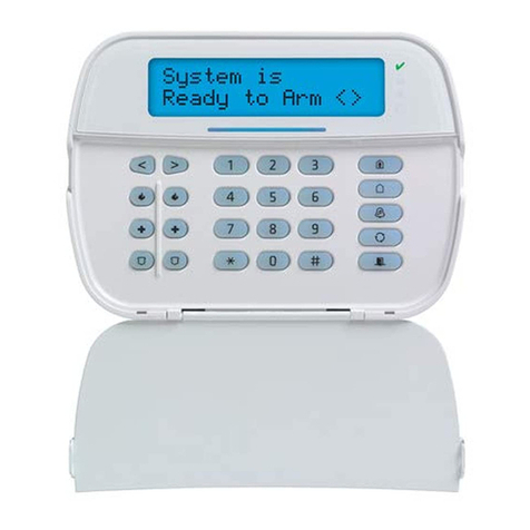
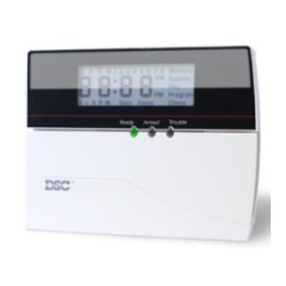
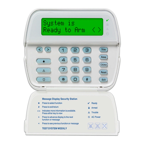
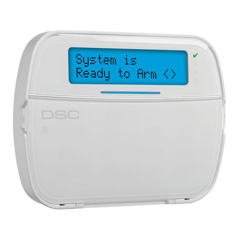
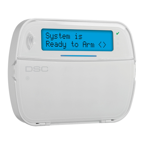
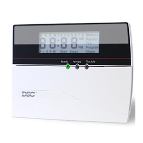
DSC PowerSeries Neo HS2TCHP User manual

HS2TCHP
Installation Instructions/Instructies voor installatie/Istruzioni di installazione/Instrukcja instalacji
WARNING: Please refer to the System Installation Manual for information on limitations regarding product use and function and information on the limitations as to liability of the manufacturer.
NOTE: These instructions shall be used in conjunction with the system Installation Manual of the Control Panel with which this equipment is intended to be used..
WARSCHUWING Raadpleeg de installatiehandleiding voor informatie over beperkingen wat betreft productgebruik en -functie, en informatie over de beperkingen van aansprakelijkheid van de fabrikant.
OPMERKING: Deze instructies moeten worden gebruikt in combinatie met de systeeminstallatiehandleiding van het centrale waarmee deze apparatuur is bestemd om te worden gebruikt.
AVVERTENZA: Fare riferimento al Manuale di installazione del sistema per informazioni sui limiti relativi all’utilizzo e alle funzioni del prodotto, e informazioni sui limiti di responsabilità del costrut-
tore.
NOTA: Le presenti istruzioni devono essere impiegate in combinazione con il manuale d’installazione del sistema della Pannello di controllo con il quale si intende utilizzare l’apparecchiatura.
OSTRZEZENIE: Informacje dotyczące ograniczeń użytkowania i funkcji produktu oraz informacje dotyczące ograniczeń odpowiedzialności producenta podano w podręczniku instalacji systemu.
UWAGA: Instrukcje zawarte w tej publikacji należy stosować łącznie z instrukcjami zawartymi w podręczniku instalacji panelu sterowania, z którym ten produkt ma być używany.

English
Installation Instructions
The HS2TCHP keypad can be used on security systems with up to 128 zones. These
keypads are compatible with the Neo PowerSeries HS2016/32/64 and HS2128 panels
V1.0 and higher.
Specifications
lTemperature range: UL/ULC: 0°C to +49°C (32°F to 120°F); EN: -10°C to +55°C
(14°F to 131°F)
lWeight: 405g
lHumidity (MAX): 93%R.H. non-condensing
lPlastic enclosure protection degree: IP30, IK04 (touchscreen excluded)
lVoltage rating: 11.3VDC to 12.5VDC nominal
lLow battery indication: 9VDC
lConnects to control panel via 4-wire Corbus
lCorbus distance: 101 m (332 ft.) (max.); Corbus distance in Extra Power mode: 54
m (177 ft)
lUp to 16 keypads per system
lHS2TCHP current draw (at 12VDC): 100 mA standby (screen off)/160 mA activ-
ated or alarm (reg. power mode)/230 mA activated or alarm (Extra Power mode).
lNote: This does not include 50 mA (max) using PGM output.
lWall mount tamper
lFive programmable function keys
lReady (Green LED), Armed (Red LED), Trouble (Yellow LED), AC (Green LED),
HOME (White LED)
lKeypad size: 191 mm x 126 mm x 20.35 mm
lDisplay area size: 155 mm x 86 mm
lSD card slot: holds any standard Secure Digital (SD) card* (32 x 24 x 2.1 mm). *If
necessary, the SD card can be formatted to file system FAT16 or 32 using a PC.
The maximum size SD card supported is 32 GB.
lWiring: standard four-wire connection
lView angle: horizontal viewing angle: 70° (left) (typ.) 70° (right) (typ.)
lVertical view angle: 70° (top), 50° (bottom) (typ.)
lBrightness: 280 cd/m2
Unpacking
The keypad package includes the following parts:
lOne keypad
lFive mounting screws and five anchors for wall-mounting
lOne tamper switch (required for UL commercial burglary listed installations)
lInstallation instructions and User manual
Mounting
Mount the keypad where it is accessible to designated points of entry and exit. Once a
dry and secure location is selected, do the following:
1. Remove the SD card before opening the touchscreen. See the following figure.
Warning: Do not disassemble the touchscreen without removing the SD card
first.
2. Remove screw at the bottom of the keypad.
3. Insert screwdriver into slots and pry up to remove.
Figure 1 - Removing the Backplate
S
D
c
a
r
d
gently
push
in
press
to
eject
4. Secure keypad backplate to the wall using mounting holes. See the following fig-
ure. Use all 4 screws provided unless mounting on a single gang box. Use the
plastic anchors if the unit is to be mounted on drywall. If using the keypad
tamper, secure the tamper plate to the wall with a screw.

Figure 2 - Mounting the Backplate
mounting hole
mounting hole
mounting hole
wiring slot
mounting hole
hole for
tamper
screw
Note: For ULC fire installations, the keypad must be mounted on top of an elec-
trical box and used with conduit.
5. Run wire through wiring slot. Connect Corbus wiring to the keypad. See the Wir-
ing section.
6. Place keypad into backplate, ensuring that the wire is pushed back into the wall as
much as possible. Route the wire inside the keypad ensuring high components are
avoided. Snap the front assembly closed, ensuring that there is no pressure to the
keypad from the wire below.
If any tension is found between the front keypad assembly and wiring, please open the
keypad, re-route the wire and close again. Repeat these steps until the keypad is closed
properly.
Wiring
1. Before wiring the unit, ensure that all power (AC transformer, telecommunications
network, and battery) is disconnected from the control panel.
2. Connect the four corbus wires from the control panel (green, yellow, black and red)
to the keypad terminals.
3. If programmed as an input, a device, such as a door contact - may be connected to
the ‘P/Z’ terminal of the keypad. This eliminates the need to run wires back to the
control panel for the device. To connect the zone, run one wire from the device to
the ‘P/Z’ terminal and the other wire from the device to the B (black) terminal. For
powered devices, run the red wire to the R (positive) terminal and the black wire to
the B (negative) terminal.
4. If the ‘P/Z’ terminal is programmed as an output, a small relay (such as DSC model
RM-1 or RM-2) or buzzer or other DC operated device may be connected between
the positive supply voltage and the ‘P/Z’ terminal (max.load is 50mA).
Note: P/Z terminal is not to be used for fire applications but can be used for low
risk ULC commercial burglary applications.
Figure 3 - Wiring
HS2TCHP
RED R
BLK B
YEL Y
GRN G
To zone or P/Z
PGM output
________
____
____
____
____
Applying Power
Once all wiring is complete, and the equipment is secured to the building structure with
at least two screws, apply power to the control panel.
1. Connect the battery leads to the battery.
2. Connect the AC transformer.
3. Connect telecommunication network (e.g., telephone line, Ethernet cable, etc.)
For more information on control panel power specifications, refer to the Control Panel
installation manual.
Caution: Route all the wiring according to the local codes and regulations
Basic Setup
This section describes how to configure the keypad, including enrollment, proximity tag
setup, function key assignment and label programming.
How to Program the Keypad
Programming consists of toggling on and off options in each section or by populating
data fields. Toggle options are enabled or disabled by pressing the corresponding num-
ber on the keypad. For example, to enable toggle options 1 and 4, press the [1] and[4]
keys. See the following diagram.

Toggle Options
To program the keypad, press [*][8][Installer Code] then use the [<][>] keys to navigate
through the menus or jump directly to a specific section by entering the section number.
To input data, use the [<][>] keys to select a character then press the keypad button for the
number/letter.
Setting the Keypad Language
Enter [000][000] then the two-digit language number.
Languages
01 = English 08 = Czech 16 = Turkish 25 = Ukrainian
(default) 09 = Finnish 17 = FFU 26 = Slovak
02 - Spanish 10 = German 18 = Croatian 27 = Serbian
03 - Portuguese 11 = Swedish 19 = Hungarian 28 = Estonian
04 - French 12 = Norwegian 20 = Romanian 29 = Slovenian
05 = Italian 13 - Danish 22 - Bulgarian
06 = Dutch 14 = Hebrew 23 = Latvian
07 = Polish 15 = Greek 24 = Lithuanian
Enrolling the Keypad
Keypads can be enrolled automatically or manually. In either case, the serial number of
the device is used as an identifier.
Note: If there is no keypad enrolled on the system, once you power up, the keypad will display the
message: Press the Enroll button on the touchscreen. Other keypads can then be enrolled from the
first keypad. Use one of the following enrollment options:
[902][000] Auto Enroll
When this mode is selected, the total number of keypads currently enrolled is displayed
on the keypad.
1. Enter [902][000] to begin the auto-enrollment of new keypads. As each device is
enrolled, the keypad displays the model type, serial number and slot assignment.
Keypads are assigned to the next available slot.
[902][001] Manual Enroll
1. Enter [902][001] or use the [<][>] keys and press [*].
2. When prompted, enter the serial number of the keypad found on the back of the
device.
3. An error tone is sounded if an invalid serial number is received. Once enrolled, the
device model, serial number and slot assignment are displayed. Keypads are
enrolled into the next available slot for the device. The slot assignment can be
changed using the [<][>] keys.
4. To cancel the enrollment of a module, press [#].
Note: Once the maximum number of devices have been enrolled, an error tone sounds and a warning
message is displayed.
[902][101] Unenroll Keypads
1. Enter [902][101] or use the [<][>] keys and press [*].
2. Use the [<][>] keys to scroll to the specific keypad to delete.
3. Press [*] to select the keypad and, when prompted, press [*] again to delete it.
Keypad Display Symbols
Ready Light (green) – If the Ready light is on, the system is ready for arming.
Armed Light (red) – If the Armed light is on, the system has been armed successfully.
System Trouble – Indicates that a system trouble is active.
AC – Indicates that AC is present at the main panel.
Proximity (Prox) Tags Support
The tag can perform any keypad function that would normally require a user access code.
Present the tag to the tag reader .
Assign Proximity Tags
Using an LCD keypad:
1. Press [*][5]Master/Supervisor Code].
2. Enter a 2-digit user code.
3. Press 2.
4. Pass the enrolled tag near the tag reader.
Delete Proximity Tags
To delete a proximity tag:

1. Select Options, Access Codes [enter Master code].
2. Select a user to delete.
3. Select Prox Tag Prog then delete.
Function Key Assignment
The HS2TCHP has 7 buttons on the Home screen, four of them programmable by the
installer. Function key 2 must always be set to "Away Armed."
To program function keys 1,3,4,5:
1. On the virtual keypad, press [*][8][Installer Code].
2. Enter [861]-[876] to program keypads 1-16 respectively.
3. Enter [001-[005] for function keys 1-5 or use the [<][>] keys and press [*].
4. Enter a 2-digit number to assign a function key operation - [00]-[68]. See Available
Function Key Options below.
5. Repeat from step 3 until function keys 1, 3, 4, 5 are programmed.
To program function key 6:
1. Press Options, Installer Menu [Installer Code], Keypad Programming then Home
Functions.
2. To display the Photo button on the Home page, press Photos. To display the
Keypad Mode button on the Home page, press Keypad Mode.
Available Function Key Options
Refer to your system installation manual for a complete list.
[00] Null [02] Instant Stay Arm [03] Stay Arm
[04] Away Arm [05] [*][9] No-entry Arm [06] [*][4] Chime ON/OFF
[07] [*][6][---][04] System Test [09] Night Arm [12] Global Stay Arm
[13] Global Away Arm [14] Global Disarming [16] [*][0] Quick Exit
[17] Arm Interior [21] [*][7][1] Command Output 1 [22] [*][7][2] Command Output 2
[23] [*][7][3] Command Output 3 [24] [*][7][4] Command Output 4 [29] Bypass Group Recall
[31] Local PGM Activate [32] Bypass Mode [33] Bypass Recall
[34] User Programming [35] User Functions [37] Time/ Date Program
[39] Trouble Display [40] Alarm Memory [61] - [68] Partition Select 1 - 8
Programming Labels
1. From the HS2TCHP keypad, press Options, press Installer Menu [Installer Code],
then press Label Programming.
2. From the Label screen, press the item that you want to label (e.g., zones, partitions,
etc.).
3. Enter the label name for the selected item.
4. Press Save when complete.
Optional Settings
The following settings are available through the Options menu.
Enable/Disable Fire, Medical, Panic Buttons
1. Press Options, Installer Menu [Installer Code], Keypad Programming, then
Options.
2. Enable/disable the desired Fire, Medical and Panic buttons.
Extra Power Option
The Extra Power option will increase the brightness of the display. To enable the option:
1. Press Options, Installer Menu [Installer Code], Keypad Programming, then
Options.
2. Enable or disable the extra power option.
Note: Enabling the Extra Power option will put the keypad into a higher current mode and the
keypad will draw 300 mA. In Extra Power mode, reduce the maximum wire length from 101 m (332
ft.) to 54 m (177 ft.)
Change the Background Image
1. Press Options, Installer Menu [Installer Code], Keypad Programming, then Back-
ground Image.
2. Select image to use from SD card as background image.
3. To exit, press the Back or the Home button.
Dark Text Enable/Disable
1. Press Options, Installer Menu [Installer Code], Keypad Programming, then
Options.
2. Select the desired text color by enabling or disabling Dark Text. (This will make
the text white).

Note: This feature affects only the text on the Classic (square) button home page.
Perform a Firmware Upgrade
1. Insert an SDcard in the HS2TCHP with the new firmware.
2. Press Options, Installer Menu [Installer Code], Keypad Programming, then Firm-
ware Upgrade.
3. Select OK to perform a firmware upgrade (if a new firmware version is available).
Keypad Programming
To enter keypad programming:
1. Press Options then Keypad Mode. The virtual keypad is displayed.
2. Press [*][8][Installer Code].
3. Enter one of the following keypad programming sections:
l[860] Keypad Slot Number. This section is for display only.
l[861]-[876] to program keypads 1-16 respectively.
Once a keypad is selected, the following programming options are available:
[000] Keypad Partition Mask
Valid entriesare 00-08. |___|___|
[011] Keypad Input/Output Programming
Zone or PGM Number Default 000 I___I___I___I
[012] Local PGM Output Pulse Activation Time
I___I___I Minutes (00-99) I___I___I Seconds(00-99)
[021] First Keypad Options
Default Value Option ON Off
ON I__I 1 FireKey Enabled FireKey Disabled
ON I__I 2 MedicalKey Enabled MedicalKey Disabled
ON I__I 3 Panic Key Enabled Panic Key Disabled
ON I__I 4 Display Access Code When Pro-
gramming
Display Xs When ProgrammingAccess
Codes
[022] Second Keypad Options
Default Value Option ON Off
ON I__I 1 Local Clock Display ON Local Clock Display OFF
OFF I__I 2 Local Clock Displays 24-hr Clock Displays AM/PM
ON I__I 3 Auto Alarm Mem Scroll ON Auto Alarm Mem Scroll OFF
ON I__I 4 For FutureUse For FutureUse
OFF I__I 5 Power LED Enabled Power LED Disabled
ON I__I 6 Power LED Indicates AC Present ON Power LED Indicates ACPresent OFF
ON I__I 7 Alarms DisplayedW hile Armed Alarms Not DisplayedWhileArmed
OFF I__I 8 Auto-ScrollOpen Zones ON Auto-ScrollOpen Zones OFF
Note:For UL/ULC installations, bit 5 (PowerLED) and bit 6 (Power LED IndicatesAC Present)
shallbe ON.
[023] Third Keypad Options
Default Value Option ON Off
OFF I__I 1 ArmedLED Power Save ArmedLED Off in Sleep Mode
ON I__I 2 KeypadStatus Shows Stay Arm KeypadStatus Shows Stay/Away Arm
OFF I__I 3 5th Terminal is Keypad PGM Output 5th Terminal is Keypad Zone Input
ON I__I 4 Prox tagwillarm/disarm Prox tagdoes not arm/disarm
OFF I__I 7 Local Display of Temperature No Local Display of Temperature
OFF I__I 8 LowTemperatureWarningEnabled LowTemperatureWarning Disabled
[030] Download LCD Messages
I___I___I___I___I___I___I___I___I___I___I___I___I___I ___I
[031] Download LCD Message Duration
Default: 000 I___I___I___I
(Valid entries are 000-255, 000=Unlimited Msg Display)Thisnumber represents the number
of timesthe downloaded message must be cleared before it ispermanentlyremoved. This
message can be cleared by pressing anykey.
[041] Indoor Temperature Zone Assignment
Default: 000 I___I___I___I (Valid entries are 000-128)
[042] Outdoor Temperature Zone Assignment
Default: 000 I___I___I___I (Valid entries are 000-128)
[101] - [228] Door Chime for Zones 1 - 128
The keypad can be programmed to make up to four different chime soundsforindividual
zones (e.g., for Zone 1, enter section [101], forZone 2 entersection [102]).
Default: 01 I___I___I
Valid Entries
01 6Beeps
02 Bing-Bingtone
03 Ding-Dongtone
04 Alarm tone (4secondduration)
05 Zone name
[991] Reset Keypad Programming to Factory Defaults
1. Press [*][8][Installer Code].
2. Enter [991].
3. Use the [<][>] keys to scroll to the applicable keypad.
4. Press [*] to select the keypad.
5. Re-enter [Installer Code].
6. Press [*] to reset the selected keypad to factory defaults.

Limited Warranty
Digital Security Controls (DSC) warrants that for a period of 12 months from the date of purchase, the
product shall be free of defects in materials and workmanship under normal use and that in fulfilment
of any breach of such warranty, DSC shall, at its option, repair or replace the defective equipment upon
return of the equipment to its repair depot. This warranty applies only to defects in parts and work-
manship and not to damage incurred in shipping or handling, or damage due to causes beyond the con-
trol of Digital Security Controls such as lightning, excessive voltage, mechanical shock, water damage,
or damage arising out of abuse, alteration or improper application of the equipment. The foregoing war-
ranty shall apply only to the original buyer, and is and shall be in lieu of any and all other warranties,
whether expressed or implied and of all other obligations or liabilities on the part of Digital Security
Controls. Digital Security Controls neither assumes responsibility for, nor authorizes any other person
purporting to act on its behalf to modify or to change this warranty, nor to assume for it any other war-
ranty or liability concerning this product. In no event shall Digital Security Controls be liable for any
direct, indirect or consequential damages, loss of anticipated profits, loss of time or any other losses
incurred by the buyer in connection with the purchase, installation or operation or failure of this
product.
Warning: Digital Security Controls recommends that the entire system be completely tested on a reg-
ular basis. However, despite frequent testing, and due to, but not limited to, criminal tampering or elec-
trical disruption, it is possible for this product to fail to perform as expected. Important Information:
Changes/modifications not expressly approved by DSC could void the user’s authority to operate this
equipment.
IMPORTANT - READ CAREFULLY: DSC Software purchased with or without Products and Com-
ponents is copyrighted and is purchased under the following license terms:
This End-User License Agreement (“EULA”) is a legal agreement between You (the company, indi-
vidual or entity who acquired the Software and any related Hardware) and Digital Security Controls, a
division of Tyco Safety Products Canada Ltd. (“DSC”), the manufacturer of the integrated security sys-
tems and the developer of the software and any related products or components (“HARDWARE”) which
You acquired.
If the DSC software product (“SOFTWARE PRODUCT” or “SOFTWARE”) is intended to be accom-
panied by HARDWARE, and is NOT accompanied by new HARDWARE, You may not use, copy or
install the SOFTWARE PRODUCT. The SOFTWARE PRODUCT includes computer software, and may
include associated media, printed materials, and “online” or electronic documentation.
Any software provided along with the Software Product that is associated with a separate end-user
license agreement is licensed to You under the terms of that license agreement.
By installing, copying, downloading, storing, accessing or otherwise using the Software Product, You
agree unconditionally to be bound by the terms of this EULA, even if this EULA is deemed to be a
modification of any previous arrangement or contract. If You do not agree to the terms of this EULA,
DSC is unwilling to license the Software Product to You, and You have no right to use it.
SOFTWARE PRODUCT LICENSE
The SOFTWARE PRODUCT is protected by copyright laws and international copyright treaties, as well
as other intellectual property laws and treaties. The SOFTWARE PRODUCT is licensed, not sold.
1. GRANT OF LICENSE This EULA grants You the following rights:
(a) Software Installation and Use - For each license You acquire, You may have only one copy of the
SOFTWARE PRODUCT installed.
(b) Storage/Network Use - The SOFTWARE PRODUCT may not be installed, accessed, displayed, run,
shared or used concurrently on or from different computers, including a workstation, terminal or other
digital electronic device (“Device”). In other words, if You have several workstations, You will have to
acquire a license for each workstation where the SOFTWARE will be used.
(c) Backup Copy - You may make back-up copies of the SOFTWARE PRODUCT, but You may only
have one copy per license installed at any given time. You may use the back-up copy solely for
archival purposes. Except as expressly provided in this EULA, You may not otherwise make copies of
the SOFTWARE PRODUCT, including the printed materials accompanying the SOFTWARE.
2. DESCRIPTION OF OTHER RIGHTS AND LIMITATIONS
(a) Limitations on Reverse Engineering, Decompilation and Disassembly - You may not reverse engin-
eer, decompile, or disassemble the SOFTWARE PRODUCT, except and only to the extent that such
activity is expressly permitted by applicable law notwithstanding this limitation. You may not make
any changes or modifications to the Software, without the written permission of an officer of DSC. You
may not remove any proprietary notices, marks or labels from the Software Product. You shall institute
reasonable measures to ensure compliance with the terms and conditions of this EULA.
(b) Separation of Components - The Software Product is licensed as a single product. Its component
parts may not be separated for use on more than one HARDWARE unit.
(c) Single INTEGRATED PRODUCT - If you acquired this SOFTWARE with HARDWARE, then the
SOFTWARE PRODUCT is licensed with the HARDWARE as a single integrated product. In this case,
the SOFTWARE PRODUCT may only be used with the HARDWARE as set forth in this EULA.
(d) Rental - You may not rent, lease or lend the SOFTWARE PRODUCT. You may not make it avail-
able to others or post it on a server or web site.
(e) Software Product Transfer - You may transfer all of Your rights under this EULA only as part of a
permanent sale or transfer of the HARDWARE, provided You retain no copies, You transfer all of the
SOFTWARE PRODUCT (including all component parts, the media and printed materials, any upgrades
and this EULA), and provided the recipient agrees to the terms of this EULA. If the SOFTWARE
PRODUCT is an upgrade, any transfer must also include all prior versions of the SOFTWARE
PRODUCT.
(f) Termination - Without prejudice to any other rights, DSC may terminate this EULA if You fail to
comply with the terms and conditions of this EULA. In such event, You must destroy all copies of the
SOFTWARE PRODUCT and all of its component parts.
(g) Trademarks - This EULA does not grant You any rights in connection with any trademarks or ser-
vice marks of DSC or its suppliers.
3. COPYRIGHT - All title and intellectual property rights in and to the SOFTWARE PRODUCT
(including but not limited to any images, photographs, and text incorporated into the SOFTWARE
PRODUCT), the accompanying printed materials, and any copies of the SOFTWARE PRODUCT, are
owned by DSC or its suppliers. You may not copy the printed materials accompanying the SOFTWARE
PRODUCT. All title and intellectual property rights in and to the content which may be accessed
through use of the SOFTWARE PRODUCT are the property of the respective content owner and may be
protected by applicable copyright or other intellectual property laws and treaties. This EULA grants
You no rights to use such content. All rights not expressly granted under this EULA are reserved by DSC
and its suppliers.
4. EXPORT RESTRICTIONS - You agree that You will not export or re-export the SOFTWARE
PRODUCT to any country, person, or entity subject to Canadian export restrictions.
5. CHOICE OF LAW - This Software License Agreement is governed by the laws of the Province of
Ontario, Canada.
6. ARBITRATION - All disputes arising in connection with this Agreement shall be determined by
final and binding arbitration in accordance with the Arbitration Act, and the parties agree to be bound
by the arbitrator’s decision. The place of arbitration shall be Toronto, Canada, and the language of the
arbitration shall be English.
7. LIMITED WARRANTY
(a) NO WARRANTY - DSC PROVIDES THE SOFTWARE “AS IS” WITHOUT WARRANTY. DSC
DOES NOT WARRANT THAT THE SOFTWARE WILL MEET YOUR REQUIREMENTS OR THAT
OPERATION OF THE SOFTWARE WILL BE UNINTERRUPTED OR ERROR-FREE.
(b) CHANGES IN OPERATING ENVIRONMENT - DSC shall not be responsible for problems caused
by changes in the operating characteristics of the HARDWARE, or for problems in the interaction of
the SOFTWARE PRODUCT with non-DSC-SOFTWARE or HARDWARE PRODUCTS.
(c) LIMITATION OF LIABILITY; WARRANTY REFLECTS ALLOCATION OF RISK - IN ANY
EVENT, IF ANY STATUTE IMPLIES WARRANTIES OR CONDITIONS NOT
STATED IN THIS LICENSE AGREEMENT, DSC’S ENTIRE LIABILITY UNDER ANY PROVISION OF
THIS LICENSE AGREEMENT SHALL BE LIMITED TO THE GREATER OF THE AMOUNT
ACTUALLY PAID BY YOU TO LICENSE THE SOFTWARE PRODUCT AND FIVE CANADIAN
DOLLARS (CAD$5.00). BECAUSE SOME JURISDICTIONS DO NOT ALLOW THE EXCLUSION OR
LIMITATION OF LIABILITY FOR CONSEQUENTIAL OR INCIDENTAL DAMAGES, THE ABOVE
LIMITATION MAY NOT APPLY TO YOU.
(d) DISCLAIMER OF WARRANTIES - THIS WARRANTY CONTAINS THE ENTIRE WARRANTY
AND SHALL BE IN LIEU OF ANY AND ALL OTHER WARRANTIES, WHETHER EXPRESSED OR
IMPLIED (INCLUDING ALL IMPLIED WARRANTIES OF MERCHANTABILITY OR FITNESS FOR A
PARTICULAR PURPOSE) AND OF ALL OTHER OBLIGATIONS OR LIABILITIES ON THE PART OF
DSC. DSC MAKES NO OTHER WARRANTIES. DSC NEITHER ASSUMES NOR AUTHORIZES ANY
OTHER PERSON PURPORTING TO ACT ON ITS BEHALF TO MODIFY OR TO CHANGE THIS
WARRANTY, NOR TO ASSUME FOR IT ANY OTHER WARRANTY OR LIABILITY CONCERNING
THIS SOFTWARE PRODUCT.
(e) EXCLUSIVE REMEDY AND LIMITATION OF WARRANTY - UNDER NO CIRCUMSTANCES
SHALL DSC BE LIABLE FOR ANY SPECIAL, INCIDENTAL, CONSEQUENTIAL OR INDIRECT
DAMAGES BASED UPON BREACH OF WARRANTY, BREACH OF CONTRACT, NEGLIGENCE,
STRICT LIABILITY, OR ANY OTHER LEGAL THEORY. SUCH DAMAGES INCLUDE, BUT ARE NOT
LIMITED TO, LOSS OF PROFITS, LOSS OF THE SOFTWARE PRODUCT OR ANY ASSOCIATED
EQUIPMENT, COST OF CAPITAL, COST OF SUBSTITUTE OR REPLACEMENT EQUIPMENT,
FACILITIES OR SERVICES, DOWN TIME, PURCHASERS TIME, THE CLAIMS OF THIRD PARTIES,
INCLUDING CUSTOMERS, AND INJURY TO PROPERTY.
WARNING: DSC recommends that the entire system be completely tested on a regular basis. However,
despite frequent testing, and due to, but not limited to, criminal tampering or electrical disruption, it is
possible for this SOFTWARE PRODUCT to fail to perform as expected.
Operating Instructions shall be made available to the user.
The trademarks, logos, and service marks displayed on this document are registered in the United States
[or other countries]. Any misuse of the trademarks is strictly prohibited and Tyco International Ltd. will
aggressively enforce its intellectual property rights to the fullest extent of the law, including pursuit of
criminal prosecution wherever necessary. All trademarks not owned by Tyco International Ltd. are the
property of their respective owners, and are used with permission or allowed under applicable laws.
Product offerings and specifications are subject to change without notice. Actual products may vary
from photos. Not all products include all features. Availability varies by region; contact your sales rep-
resentative.
This product contains open source components QT Version 4.7.3 and Linux Kernel License: Version 2.6.
Both of these components are protected by copyright and have terms and conditions associated with
their use. The open source software code and associated components used in this product are down-
loadable from the DSC website. Please visit
http://www.dsc.com/open-source-documentation for detailed information.
FCC Compliance Statement - CAUTION: Changes or modifications not expressly approved by DSC
could void your authority to use this equipment.
This equipment generates and uses radio frequency energy and if not installed and used properly, in
strict accordance with the manufacturer’s instructions, may cause interference to radio and television
reception. It has been type tested and found to comply with the limits for Class B device in accordance
with the specifications in Subpart “B” of Part 15 of FCC Rules, which are designed to provide reas-
onable protection against such interference in any residential installation. However, there is no guar-
antee that interference will not occur in a particular installation. If this equipment does cause
interference to television or radio reception, which can be determined by turning the equipment off
and on, the user is encouraged to try to correct the interference by one or more of the following
measures:
• Re-orient the receiving antenna
• Relocate the alarm control with respect to the receiver
• Move the alarm control away from the receiver
• Connect the alarm control into a different outlet so that alarm control and receiver are on different
circuits.
If necessary, the user should consult the dealer or an experienced radio/television technician for addi-
tional suggestions. The user may find the following booklet prepared by the FCC helpful: “How to
Identify and Resolve Radio/Television Interference Problems”. This booklet is available from the U.S.
Government Printing Office, Washington, D.C. 20402, Stock # 004-000-00345-4.
Industry Canada Compliance Statement
CAN ICES-3(b)/NMB-3(b)
For Commercial Fire Monitoring applications the HS2TCHP keypad is for supplementary
use only.
EN50131-1 Grade2/Class II
The Model HS2TCHPKeypad has been certified by Telefication according to
EN50131-1:2006 + A1:2009, EN50131-3:2009 for Grade 2, Class II.
Notes:For EN50131 compliant installations the following functions (initiated from
the keypad emergency buttons) have to be disabled:
- Fire Alarm function
- Auxiliary (Medical) Alarm function
- Panic Alarm function
©2017 Tyco Security Products. All Rights Reserved • www.dsc.com •
Tech Support: 1-800-387-3630 (Canada, US), 905-760-3000

Installatie instructies
De HS2TCHP toetsenbord kan worden gebruikt beveiligingssystemen met maximaal 128
zones. Deze toetsenborden zijn compatibel met de Neo machtreeksen HS2016 / 32/ 64 en
HS2128 panelen V1.0 en hoger.
Specificaties
lTemperatuursbereik: UL/ULC: 0°C tot +49°C (32°F tot 120°F); EN: -10°C tot
+55°C (14°F tot 131°F)
lLuchtvochtigheid (MAX): 93%R.H. niet-condenserend
lBeschermingsgraad kunststof behuizing: IP30, IK04 (aanraakscherm niet inbe-
grepen)
lOpgegeven spanning: 11,3 V gelijkspanning naar 12,5 V gelijkspanning nomi-
naal
lIndicatie voor batterij bijna leeg: 9 V gelijkspanning
lAansluiting op het bedieningspaneel via 4-draads Corbus
lCorbusafstand: 101 m (332 voet) (maximaal); corbusafstand in Extra ver-
mogenmodus: 54 m (177 voet)
lMaximaal 16 bedienpanelen per systeem
lStroomverbruik HS2TCHP (bij 12 VDC): 100 mA standby (scherm uit)/160 mA
geactiveerd of alarm (reg. vermogenmodus)/230 mA geactiveerd of alarm (Extra ver-
mogenmodus) Opmerking: Dit omvat geen 50 mA (maximaal) met gebruik-
making van een PGM-uitgang.
lMuurbevestiging met sabotagebeveiliging
l5 programmeerbare functietoetsen
lGereed (groene LED), Geactiveerd (rode LED), Probleem (gele LED), licht-
netspanning (groene LED:), START (witte LED)
lAfmetingen toetsenpaneel: 191 mm x 126 mm x 20,35 mm
lAfmetingen weergavegedeelte: 155 mm x 86 mm
lSD-kaartsleuf: voor iedere standaard “Secure Digital” (SD)-kaart* (32 x 24 x 2,1
mm). *Indien nodig kan de SD-kaart met gebruikmaking van een PC worden
geformatteerd in het bestandssysteem FAT16 of 32. De maximaal ondersteunde
omvang voor de SD-kaart is 32 GB.
lBedrading: Standaard vierdraads aansluiting
lKijkhoek: horizontale kijkhoek: 70° (links)(type) 70° (rechts)(type)
lVerticaal beeldhoek: 70° (boven), 50° (onder) (typ.)
lHelderheid: 280 cd/m2
Uitpakken
Het bedienpaneel pakket omvat het volgende:
lEen bedienpaneel
lVijf pluggen en vijf bevestigingsschroeven voor montage op een wand
lEen sabotageschakelaar (vereist voor commerciële, UL-geregistreerde inbraak-
installaties
lInstallatie-instructies en gebruiksaanwijzing
Montage
Bevestig het bedienpaneel op een plaats waar het toegankelijk is vanaf aangewezen
ingang- en uitgangspunten. Handel zodra er een droge en veilige plaats is geselecteerd als
volgt:
1. Verwijder voor het openen van het aanraakscherm de SD-kaart. Zie de volgende
afbeelding.
Waarschuwing: Demonteer het aanraakscherm niet voordat u eerst de SD-kaart ver-
wijdert.
2. Verwijder de schroef aan de onderkant van het bedienpaneel.
3. Steek een schroevendraaier in de sleuf en wrik hem omhoog om hem te ver-
wijderen.
Afbeelding 1 - Het verwijderen van het achterpaneel
4. Monteer de achterplaat van het bedienpaneel door de bevestigingsgaten aan de
wand. Zie de volgende afbeelding. Gebruik alle 4 bijgeleverde schroeven, tenzij u
het toestel monteert op een enkele wandcontactdoos. Gebruik de plastic pluggen
als het apparaat op gipsplaat wordt gemonteerd. Beveilig de sabotageplaat aan de

muur met een schroef wanneer u de sabotagebeveiliging voor het bedienpaneel
gebruikt.
Afbeelding 2 - Het monteren van het achterpaneel
Opmerking: Het toetsenpaneel moet bij ULC brandinstallaties bovenop een elektrische
kast worden gemonteerd en met een kabelgoot worden gebruikt.
5. Leid de bedrading door de bedradingssleuf. Sluit de bedrading aan op het toet-
senpaneel. Zie de sectie bedrading.
6. Bevestig het bedienpaneel op de achterplaat, zorg ervoor dat de kabel zo ver als
mogelijk in de wand is geduwd. Leid de kabel binnen in het bedienpaneel, zorg
ervoor dat de hogere componenten niet worden aangeraakt. Klap het frontplaatje
dicht, zorg ervoor dat de kabel onderaan geen druk uitoefent op het bedienpaneel.
Als u merkt dat er druk wordt uitgeoefend tussen het frontplaatje en de bedrading,
doe dan het bedienpaneel opnieuw open, herleid de kabel en sluit opnieuw. Her-
haal deze stappen tot het bedienpaneel juist sluit.
Bekabeling
1. Voordat het apparaat van bedrading kan worden voorzien, dient u te zorgen dat
alle stroomtoevoer (transformator, telecommunicatienetwerk en batterij) van de cen-
trale is ontkoppeld.
2. Sluit de vier draden van het bedieningspaneel (groen, geel, zwart en rood) aan op
de aansluitklemmen van het toetsenpaneel.
3. Indien geprogrammeerd als ingang, kan een apparaat, zoals een deurcontact, wor-
den aangesloten op de “P/Z”-aansluiting van het bedienpaneel. Hierdoor is het niet
nodig om draden terug naar de centrale te laten lopen vanaf het apparaat. Om de
zone aan te sluiten laat u één draad vanaf het apparaat naar de “P/Z”-aansluitklem
lopen en de andere draad vanaf het element naar de B (zwarte) aansluitklem. Voor
stroomgevoede elementen leidt u de rode draad naar de R (positieve) aansluitklem
en de zwarte draad naar de B (negatieve) aansluitklem.
4. Wanneer de P/Z-aansluitklem als een uitgang is geprogrammeerd, een klein relais
(bijvoorbeeld DSC model RM-1 of RM-2) of zoemer of ander DC-apparaat inrich-
ting kan worden aangesloten tussen de positieve voedingsspanning en de P/Z-ter-
minal (maximale belasting is 50 mA).
Opmerking: De P/Z aansluiting mag niet voor brandtoepassingen worden gebruikt, maar
kan worden gebruikt voor ULC commerciële inbraaktoepassingen met laag risico.
Afbeelding 3 - Bedrading
Stroom inschakelen
Wanneer alle bedrading is aangelegd, en het toestel met tenminste twee schroeven aan de
infrastructuur is bevestigd, schakelt u het bedieningspaneel in.
1. Sluit de batterijverbindingen aan op de batterij.
2. Sluit de ac transformator aan.
3. Sluit het telecommunicatienetwerk aan (bijv. telefoonlijn, Ethernetkabel enz.)
Voor meer informatie over de stroomspecificaties van de bedieningspaneel, raadpleegt u
de installatiehandleiding van de centrale.
Voorzichtigheid: Leid alle bedrading in overeenstemming met de lokale regels en voor-
schriften
Basisinstelling
Dit deel beschrijft hoe het bedienpaneel kan worden geconfigureerd, inclusief registratie,
proximity tag-instelling, toewijzing van functietoetsen en labelprogrammering.

Het programmeren van het toetsenpaneel
Programmering bestaat uit het aan en uit zetten van opties in elke sectie of door het bevol-
ken van gegevensvelden. Schakelopties worden ingeschakeld of uitgeschakeld door op
het corresponderende nummer op het bedienpaneel te drukken. Om bijvoorbeeld scha-
kelopties 1 en 4 in te schakelen, drukt u op de [1] en [4]-toetsen. (zie het volgende
schema).
Schakelopties
Druk om het toetsenpaneel te programmeren [*][8][Installateurscode] en gebruik dan de
toetsen [<][>] om door de menu's te navigeren of spring direct naar een bepaalde sectie
door het sectienummer in te voeren.
Voor het invoeren van gegevens, gebruikt u de [<][>]-toetsen om een teken te selecteren
en drukt u vervolgens op de bedienpaneeltoets voor het nummer/letter.
Het instellen van de taal van het toetsenpaneel
Voer [000][000] en dan het tweecijferige nummer van de taal in.
Talen
01 = Engels 08 = Tsjechisch 16 = Turken 25 = Oekraïens
(standaard) 09 = Fins 17 = FFU 26 = Slowaaks
02 = Spaans 10 = Duits 18 = Kroatisch 27 = Servisch
03 = Portugees 11 = Zweeds 19 = Hongaars 28 = Ests
04 = Frans 12 = Noors 20 = Roemeens 29 = Sloveens
05 = Italiaans 13 = Deens 22 = Bulgaars
06 = Nederlands 14 = Hebreeuws 23 = Lets
07 = Pools 15 = Grieks 24 = Litouws
Inbedrijfstelling van het bedienpaneel
Bedienpanelen kunnen automatisch of handmatig worden geregistreerd. In beide gevallen
wordt het serienummer van het apparaat als identificatie gebruikt.
Opmerking: Als er geen bedienpaneel geregistreerd is op het systeem geeft het bedienpaneel tij-
dens het opstarten het volgende bericht weer: Druk de toets Registreren op het aanraakscherm.
Andere bedienpanelen kunnen vervolgens worden geregistreerd vanaf het eerste bedienpaneel.
Gebruik een van de volgende opties om te registreren:
[902][000] Automatisch aanmelden
Als deze modus is geselecteerd, wordt het totale aantal bedienpanelen dat momenteel is
geregistreerd op het bedienpaneel weergegeven.
1. Voer [902][000] om met de automatische registratie van nieuwe bedienpanelen te
beginnen. Tijdens het aanmelden van ieder apparaat geeft het bedienpaneel het
soort model, serienummer en plaats toewijzing aan. Bedienpanelen worden toe-
gewezen aan de volgende beschikbare positie.
[902][001] Handmatig aanmelden
1. Voer [902][001] of gebruik de [<][>]-toetsen en druk op [*].
2. Voer wanneer daarom wordt gevraagd, het serienummer van de module, die op de
achterkant van het apparaat staat, in.
3. Er klinkt een foutsignaal als er een ongeldig serienummer is ontvangen. Eenmaal
geregistreerd, worden het apparaatmodel, het serienummer en de positietoewijzing
weergegeven. Bedienpanelen worden geregistreerd op de volgende beschikbare
plaats voor het apparaat. De plaats toewijzing kan worden gewijzigd met behulp
van de navigatietoetsen [<][>].
4. Druk om toevoeging van een module te annuleren op [#].
Opmerking: Zodra het maximum aantal apparaten zijn aangemeld, klinkt een fout toon en wordt
een waarschuwingsbericht weergegeven.
Een blok aan het bedienpaneel toewijzen
Het bedienpaneel zal moeten worden toegewezen aan een blok als controle of bedien-
paneel zones worden gebruikt. De toekenning van een keypad en de programmering van
de bedienpaneel opties moeten voor ieder bedienpaneel afzonderlijk worden uitgevoerd.
Voor elk bedienpaneel dat op het systeem is geïnstalleerd:
1. Druk op [*][8][installatiecode].
2. Voer [861]-[876] voor bedienpaneelprogrammering en het bedien-
paneelblokmasker, wat overeenkomt met bedienpanelen 1-16.
3. Druk op [*] voor bloktoewijzing.
4. Voer 01-08 voor bloktoewijzing of gebruik de [<][>]-toetsen om naar de specifieke
blok te scrollen. Als er geen blokken worden gebruikt, voert u [01] in. Voor alge-
mene bedienpanelen (Globale Bedienpanelen) ) drukt u op [00].
5. Druk twee keer op de toets [#] om programmering te verlaten.

6. Herhaal deze procedure op elk bedieningspaneel totdat deze allemaal zijn toe-
gewezen aan de juiste blok.
[902][101] Afmelden bedienpaneel
1. Voer [902][101] of gebruik de [<][>]-toetsen en druk op [*].
2. Gebruik de [<][>]-toetsen om naar het specifiek bedienpaneel dat moet worden ver-
wijderd te scrollen.
3. Druk op [*] om het toetsenpaneel te selecteren en druk als daarom wordt gevraagd
weer op [*] om het te verwijderen.
Weergavesymbolen
Gereedlampje (groen) - Wanneer het gereedlampje aan staat, is het systeem klaar om inge-
schakeld te worden.
Inschakelingslampje (rood) - Wanneer het inschakelingslampje aan is, is het systeem inge-
schakeld.
Systeemprobleem - Geeft aan dat er een systeemprobleem actief is.
AC - Geeft aan dat er AC-stroom wordt gebruikt door het hoofdpaneel.
Ondersteuning Proximity (Prox) tag
Het label kan worden gebruikt voor het uitvoeren van iedere functie van het toet-
senpaneel, waarvoor normaal gesproken een toegangscode van een gebruiker nodig is, of
om een programmeerbare uitgang te activeren. Presenter de tag aan de taglezer .
Proximity Tags toewijzen
Met behulp van een LCD-bedienpaneel:
1. Druk op [*][5][Master/bewakerscode].
2. Toets een 4-cijferige gebruikerscode.
3. Druk op 2.
4. Beweeg de geregistreerde tag voorbij de taglezer.
Proximity Tags verwijderen
Het verwijderen van een nabijheidslabel
1. Selecteer Opties, Toegangscodes [voer mastercode in].
2. Selecteer een gebruiker om te verwijderen.
3. Selecteer Prox tag en verwijder.
Functieknoptoewijzing
De HS2TCHP heeft 7 knoppen op het scherm Start, waarvan er 4 kunnen worden gepro-
grammeerd door de installateur. Functietoets 2 moet altijd zijn ingesteld op Afwezig inge-
schakeld.
Om functietoetsen 1, 3, 4, 5 te programmeren:
1. Druk op het virtuele bedienpaneel op [*][8][Installateurscode].
2. Voer [861]-[876] in om bedienpanelen 1-16 te programmeren.
3. Voer [001]-[005] in voor functietoetsen 1-5 of gebruik de [<][>]-toetsen en
druk op [*].
4. Voer een 2-cijferig nummer in om een functietoetsbewerking aan toe te wij-
zen - [00]-[68]. Zie de beschikbare opties voor functietoetsen hieronder.
5. Herhaal vanaf stap 3 tot functietoetsen 1, 3, 4, 5 zijn geprogrammeerd.
Om functietoets 6 te programmeren:
1. Druk Opties, Installateurmenu [Installateurcode], Bedienpaneel pro-
grammeren en dan Startfuncties.
2. Druk op Foto's om de knop Fotomodus weer te geven op de startpagina.
Druk op Bedienpaneelmodus op de startpagina om de knop Bedien-
paneelmodus weer te geven op de startpagina.
Beschikbare functietoetsopties
Zie de installatiehandleiding van het systeem voor een volledige lijst.
[00] Nul [02] Onmiddellijk Aanwezig Inscha-
keling [03] Aanwezig Inschakeling
[04] Afwezig Inschakeling [05] [*][9] Geen toegang inscha-
kelen [06] [*] [4] Deurbel AAN/UIT
[07] [*][6][---][04] Sys-
teemtest [09] Nachtstand Inschakeling [12] Overal Aanwezig Inscha-
keling
[13] Overal Afwezig Inscha-
keling [14] Overal Uitschakeling [16] [*][0] Snel afsluiten
[17] Binnenshuis inschakelen [21] [*][7][1] Opdrachtuitgang 1 [22] [*][7][2] Opdrachtuitgang 2
[23] [*][7][3] Opdrachtuitgang
3[24] [*][7][4] Opdrachtuitgang 4 [29] Groep terugbrengen onder-
drukken
[31] Lokale PGM activeren [32] Overbruggingsmodus [33] Terugbrengen onderdrukken
[34] Gebrui-
kersprogrammering [35] Gebruikersfuncties [37] Tijd & datum pro-
grammeren

[39] Probleemweergave [40] Alarmen in geheugen [61] - [68] Blokselectie 1 - 8
Programmeren van labels
1. Druk op het HS2TCHP bedienpaneel Opties, Installateurmenu [Installateurcode], en
dan Label programmeren.
2. Druk in het scherm Label op het onderdeel dat u wilt labelen (bijv. zones, Bloks
enz.).
3. Voer de naam van het label voor het geselecteerd onderdeel in.
4. Druk als u klaar bent op Opslaan.
Optionele instellingen
De volgende instellingen zijn via het menu Opties beschikbaar.
In-/uitschakelen brand-, medische en paniek-
knoppen
1. Druk Opties, Installateurmenu [Installateurcode], Programmeren bedienpaneel en
dan Opties.
2. In-/uitschakelen van de gewenste brand-, medische en paniekknoppen.
Optie extra vermogen
De optie extra vermogen verhoogt de helderheid van het scherm. Om de optie in te scha-
kelen:
1. Druk Opties, Installateurmenu [Installateurcode], Programmeren bedienpaneel en
dan Opties.
2. In- of uitschakelen van de optie extra vermogen.
Opmerking: Door het inschakelen van de optie extra vermogen wordt het bedienpaneel in een
hogere stroommodus geschakeld en trekt het bedienpaneel 300 mA. In Extra Vermogenmodus, dient
u de maximale draadlengte te verkorten van 101 m (332 voet) tot 54 m (177 voet)
Het wijzigen van de achtergrondafbeelding
1. Druk Opties, Installateurmenu [Installateurcode], Programmeren bedienpaneel en
dan achtergrondafbeelding.
2. Selecteer de als achtergrondafbeelding te gebruiken afbeelding van de SD-kaart.
3. Om te verlaten drukt u op de Terug of Start knop.
Het uitvoeren van een firmware-upgrade
1. Steek een SD-kaart met de nieuwe firmware in de HS2TCHP.
2. Druk Opties, Installateurmenu [Installateurcode], Programmeren bedienpaneel en
dan Firmware.
3. Selecteer OK om de firmware-upgrade uit te voeren (als er een nieuwe firm-
wareversie beschikbaar is).
Bedienpaneel programmering
Om naar programmering toetsenpaneel te gaan:
1. Druk op Opties en dan op de modus Toetsenpaneel. Het virtuele toetsenpaneel
wordt weergegeven.
2. Druk op [*][8][installatiecode].
3. Ga naar een van de volgende secties voor de programmering van het toet-
senpaneel:
l[860] Bedienpaneel plaats nummer. Deze sectie is alleen voor weer-
gave.
l[861]-[876] om respectievelijk toetsenpanelen 1-16 te programmeren.
Zodra er een toetsenpaneel is geselecteerd, zijn de volgende programmeeropties beschik-
baar:
[000] Bedienpaneel partitie masker
I___I___I Geldigeinvoerenzijn 01-08.
[011] Bedienpaneel ingang/uitgang programmeren
Zoneof PGM-nummer Standaard000 I___I___I___I
[012] Activeringstijd lokale PGM-uitvoerpuls
I___I___I Minuten(00-99) I___I___I Seconden (00-99)
[021] Eerste Bedienpaneel opties
Standaard Waarde Optie AAN Uit
AAN I__I 1 Brandtoets ingeschakeld Brandtoets uitgeschakeld
AAN I__I 2 Medische toets ingeschakeld Medische toets uitgeschakeld
AAN I__I 3 Paniektoets ingeschakeld Paniektoets uitgeschakeld
AAN I__I 4 Toegangscodeweergeven tijdens
het programmeren
Xs weergeven bij het pro-
grammerenvantoegangscodes

Opmerking: Bij systemen die voldoen aan EN50131-1/EN50131-3 moeten de opties 1 en 2 in sec-
tie [021] UIT zijn.
[022] Opties tweehet bedienpaneel
Standaard Waarde Optie AAN Uit
AAN I__I 1 Lokaleklokweergave AAN Lokale klokweergaveUIT
UIT I__I 2 Lokaleklok toont 24-uurstijd Klok geeft AM/PM weer
AAN I__I 3 Geh. scrollenautoalarm AAN Geh. scrollenautoalarm UIT
AAN I__I 4 Voor toekomstiggebruik Voor toekomstiggebruik
UIT I__I 5 Stroom-LEDingeschakeld Stroom-LEDuitgeschakeld
AAN I__I 6 Stroom-LEDgeeft indicatieAC
aanwezigAAN
Stroom-LEDgeeft indicatieACaan-
wezigUIT
AAN I__I 7 Alarmen weergeven wanneer inge-
schakeld
Alarmenniet weergegeven wanneer
ingeschakeld
UIT I__I 8 Auto. scrollen open zones AAN Auto. scrollen open zones UIT
Opmerking: Bij UL-/ULC-installaties moeten bit 5 (LED voor stroom) en bit 6 (LED voor stroom
die aangeeft dat er lichtnetspanning aanwezig is) AAN zijn.
[023] Opties derhet bedienpaneel
Standaard Waarde Optie AAN Uit
VAN I__I 1 IngeschakeldLED-stroom-
besparing
Inschakelings-LEDuit indeslaap-
stand
AAN I__I 2 Bedienpaneel status geeft aan-
wezigingeschakeldweer
Bedienpaneel status geeft aan-
wezig/afwezigingeschakeldweer
UIT I__I 3 5e terminal is bedienpaneel
PGM-uitvoer
5e terminal is bedienpaneelzone-
invoer
AAN I__I 4 Nabijheidslabelschakelt in/uit Nabijheidslabelschakelt niet in/uit
UIT I__I 7 Lokaletemperatuurweergave Geen localetemperatuurweergave
UIT I__I 8 Waarschuwinglagetem-
peratuur ingeschakeld
Waarschuwinglage temperatuur uit-
geschakeld
[030] LCD-bericht gedownload
I___I___I___I___I___I___I___I___I___I___I___I___I___I ___I
[031] Duur gedownload LCD-bericht
Standaard: 000 I___I___I___I
(Geldige waarden zijn 000-255, 000=Onbeperkte weergave berichten). Dit nummer geeft
het aantal keren aan dat het gedownloade bericht moet worden verwijderd, voordat het per-
manent wordt verwijderd. Dit bericht kan worden gewist door op een willekeurige toets te
drukken.
[041] Toewijzingen temperatuurzone binnenshuis
Standaard: 000 I___I___I___I (Geldige waarden zijn 000-128)
[042] Toewijzingen temperatuurzone buitenshuis
Standaard: 000 I___I___I___I (Geldige waarden zijn 000-128)
[101] - [228] Deurbel voor zones 1 - 128
De keypad kan worden geprogrammeerd om tot vier verschillende tonen voor indi-
viduele zones te gebruiken, voer (bijv. voor zone 1 sectie [101] in, en voor zone 2 sectie
[102]).
Standaard: 01 I___I___I
Geldige waarden
01 6pieptonen
02 Plingpling-toon
03 Dingdong-toon
04 Alarmtoon (4 secondenlang)
05 Zone naam
[991] Programmering van het bedienpaneel terugzetten naar de fabrieksinstellingen
1. Druk op [*][8][installatiecode].
2. Voer [991] in.
3. Gebruik de [<][>]-toetsen om naar het betreffende bedienpaneel te scrollen.
4. Druk op [*] om het bedienpaneel te selecteren.
5. Voer opnieuw [installieprogrammacode] in.
6. Druk op [*] om het geselecteerde bedienpaneel te resetten naar de fabrieks-
instellingen.
Beperkte garantie
Digital Security Controls (DSC) garandeert gedurende een periode van 12 maanden vanaf de datum van
aankoop dat het product bij normaal gebruik vrij is van materiële defecten en fabricagefouten en dat
ter voldoening van een schending van zulke garantie, DSC, naar eigen keuze, bij teruggave van de appa-
ratuur bij het reparatiepunt, de defecte apparatuur zal repareren of vervangen. Deze garantie geldt
alleen voor materiële defecten en fabricagefouten en niet voor beschadigingen opgelopen tijdens ver-
zending en afhandelingsfouten, of schade als gevolg van oorzaken buiten de controle van Digital Secu-
rity Controls zoals bliksem, te hoge spanning, mechanische schokken, waterschade of schade die
voortvloeit uit misbruik, wijziging of onjuiste toepassing van de apparatuur. De voornoemde garantie
geldt alleen voor de oorspronkelijke koper en vervangt en zal alle andere garanties vervangen, expli-
ciet of impliciet, en alle andere verplichtingen of aansprakelijkheden van de kant van Digital Security
Controls. Digital Security Controls is niet verantwoordelijk voor en autoriseert niemand anders om

namens DSC op te treden om deze garantie te wijzigen of te veranderen, en aanvaardt geen andere
garantie of aansprakelijkheid betreffende dit product. In geen geval zal Digital Security Controls aan-
sprakelijk zijn voor enige directe, indirecte of gevolgschade, verlies van verwachte winst, verlies van
tijd of enige andere verliezen van de koper in verband met de aankoop, installatie, bediening of falen
van dit product.
Arschuwing: Digital Security Controls raadt u aan het hele systeem regelmatig te laten testen. Het is
echter mogelijk dat dit product, ondanks regelmatig testen en vanwege, maar niet beperkt tot, cri-
minele sabotage of stroomstoringen, niet naar verwachting presteert, Echter, ondanks regelmatige tests,
en vanwege, maar niet beperkt tot, criminele sabotage of elektronische storing, is het mogelijk dat dit
product niet naar verwachting presteert. Belangrijke informatie: Wijzigingen/modificaties die niet uit-
drukkelijk door Digital Security Controls zijn goedgekeurd, kunnen de bevoegdheid van de gebruiker
om deze apparatuur te bedienen nietig verklaren.
BELANGRIJK - ZORGVULDIG LEZEN: DSC Software, aangeschaft met of zonder Producten en Onder-
delen is auteursrechtelijk beschermd en wordt aangeschaft onder de volgende licentievoorwaarden:
Deze Overeenkomst voor eindgebruikers ("gebruiksrechtovereenkomst") is een wettelijke overeenkomst
tussen u (het bedrijf, persoon of entiteit die de software en alle bijbehorende hardware heeft verworven)
en Digital Security Controls, een divisie van Tyco Safety Products Canada Ltd ("DSC"), de fabrikant
van geïntegreerde beveiligingssystemen en de ontwikkelaar van de software en alle aanverwante pro-
ducten of componenten ("HARDWARE") die u hebt verworven.
Indien het DSC-softwareproduct (“SOFTWAREPRODUCT” of “SOFTWARE”) is bestemd om samen
met HARDWARE te worden geleverd en dit NIET vergezeld gaat van de nieuwe HARDWARE, mag U
het SOFTWAREPRODUCT niet gebruiken, kopiëren of installeren. Het SOFTWAREPRODUCT omvat
computersoftware en kan begeleidende media, gedrukte materialen en “online” of elektronische docu-
mentatie omvatten.
Software die samen met het SOFTWAREPRODUCT wordt geleverd, en die valt onder een afzonderlijke
gebruikersovereenkomst, wordt aan U in licentie gegeven onder de voorwaarden van die licen-
tieovereenkomst.
Door het SOFTWAREPRODUCT te installeren, te kopiëren, te downloaden, op te slaan, te openen of
anderszins te gebruiken, stemt U er onvoorwaardelijk mee in gebonden te zijn aan de voorwaarden in
deze Overeenkomst, zelfs als deze Overeenkomst wordt beschouwd als een wijziging van vorige rege-
lingen of contracten. Indien U niet instemt met de bepalingen van deze Overeenkomst, is DSC niet
bereid het SOFTWAREPRODUCT aan U in licentie te geven, en hebt U niet het recht om het te gebrui-
ken.
LICENTIE SOFTWAREPRODUCT
Het SOFTWAREPRODUCT wordt zowel beschermd door auteursrechtwetgeving en internationale
auteursrechtverdragen als door andere wetten en verdragen met betrekking tot intellectueel eigendom.
Het SOFTWAREPRODUCT wordt niet verkocht, maar in licentie gegeven.
1. LICENTIEVERLENING Deze gebruiksrechtovereenkomst verleent u de volgende rechten:
(a) Installatie en gebruik van de Software - voor elke licentie die u aanschaft, mag u slechts één kopie
van het SOFTWAREPRODUCT installeren.
(b) Opslag/Netwerkgebruik - het SOFTWAREPRODUCT mag niet gelijktijdig worden geïnstalleerd, geo-
pend, weergegeven, uitgevoerd, gedeeld of gebruikt op of vanaf verschillende computers, zoals een werk-
station, terminal of ander digitaal elektronisch apparaat ("Apparaat"). Oftewel, indien U meerdere
werkstations hebt, zult U een licentie moeten aanschaffen voor elk werkstation waarop de SOFTWARE
zal worden gebruikt.
(c) Back-up kopie - U mag back-up kopieën van het SOFTWAREPRODUCT maken, maar u mag op
enig gegeven moment slechts een exemplaar per licentie geïnstalleerd hebben. U mag de reservekopie
uitsluitend voor archiveringsdoeleinden gebruiken. Behalve voor zover dit expliciet in deze Over-
eenkomst wordt toegestaan, mag U verder geen kopieën van het SOFTWAREPRODUCT maken. Het-
zelfde geldt voor de afgedrukte materialen die bij de SOFTWARE worden meegeleverd.
2. BESCHRIJVING VAN ANDERE RECHTEN EN BEPERKINGEN
(a) Beperking op reverse-engineering, decompileren en disassembleren - U mag het
SOFTWAREPRODUCT niet onderwerpen aan reverse-engineering, decompileren en disassembleren, ten-
zij en voor zover dit, niettegenstaande deze beperking, uitdrukkelijk is toegestaan op grond van toe-
passelijk dwingend recht. U mag geen veranderingen of wijzigingen aan de Software maken zonder de
geschreven toestemming van een functionaris van DSC. U mag geen beschermde mededelingen, merken
of etiketten van het Softwareproduct verwijderen. U zult redelijkerwijs maatregelen nemen om te vol-
doen aan de bepalingen en voorwaarden van deze Overeenkomst.
(b) Scheiding van onderdelen - het SOFTWAREPRODUCT wordt in licentie gegeven als één product.
De componenten mogen niet worden gescheiden voor gebruik op meer dan één HARDWARE-eenheid.
(c) Eén GEÏNTEGREERD PRODUCT - als U deze SOFTWARE met HARDWARE hebt verkregen, is
het SOFTWAREPRODUCT in licentie gegeven met de HARDWARE als één geïntegreerd product. In
dat geval mag het SOFTWAREPRODUCT alleen worden gebruikt in combinatie met de HARDWARE,
zoals in deze Overeenkomst is uiteengezet.
(d) Verhuur - U mag het SOFTWAREPRODUCT niet verhuren, in lease geven of uitlenen. U mag het
niet beschikbaar maken voor anderen of het op een server of website plaatsen.
(e) Overdracht van het Softwareproduct - U mag al Uw rechten die voortvloeien uit deze Overeenkomst
uitsluitend als onderdeel van een permanente verkoop of overdracht van de HARDWARE overdragen,
mits U geen exemplaar behoudt, U het volledige SOFTWAREPRODUCT overdraagt (inclusief alle
onderdelen, de media en het gedrukte materiaal, alle upgrades en deze Overeenkomst), en mits de ont-
vanger met de bepalingen van deze Overeenkomst instemt. Indien het SOFTWAREPRODUCT een
upgrade is, moet elke overdracht tevens alle vorige versies van het SOFTWAREPRODUCT omvatten.
(f) Beëindiging - onverminderd al zijn overige rechten mag DSC deze Overeenkomst beëindigen indien
U de bepalingen van deze Overeenkomst niet nakomt. In dat geval dient u alle exemplaren en alle
componenten van het SOFTWAREPRODUCT te vernietigen.
(g) Handelsmerken - aan deze Overeenkomst kunt U geen enkel recht ontlenen in verband met enig
merk of servicemerk van DSC of zijn leveranciers.
3. AUTEURSRECHT - Alle aanspraken en intellectuele eigendomsrechten in en op het
SOFTWAREPRODUCT (inclusief, maar niet beperkt tot alle afbeeldingen, foto's en tekst die in het
SOFTWAREPRODUCT zijn verwerkt), de begeleidende gedrukte materialen en alle kopieën van het
SOFTWAREPRODUCT, zijn eigendom van DSC of haar leveranciers. U mag de begeleidende afge-
drukte documentatie van het SOFTWAREPRODUCT niet kopiëren. Alle rechten met betrekking tot de
titel en het intellectuele eigendom van de inhoud, waartoe toegang kan worden verkregen door het
gebruik van het SOFTWAREPRODUCT, berusten bij de desbetreffende eigenaar van de inhoud en kun-
nen zijn beschermd door toepasselijk auteursrecht of andere wetten en verdragen met betrekking tot
intellectueel eigendoms. Deze overeenkomst verleent u geen recht dergelijke inhoud te gebruiken. Alle
rechten die niet expliciet krachtens deze Overeenkomst worden verleend, berusten bij DSC en zijn leve-
ranciers.
4. EXPORTBEPERKINGEN - U stemt ermee in dat u het SOFTWAREPRODUCT niet exporteert of her-
exporteert naar een land, persoon of entiteit onderworpen aan Canadese exportbeperkingen.
5. GERECHTSKEUZE - Deze licentieovereenkomst voor software is onderhavig aan de wetten van de
provincie Ontario, Canada.
6. ARBITRAGE - Alle geschillen die in verband met deze overeenkomst ontstaan worden bepaald door
definitieve en bindende arbitrage in overeenstemming met de Arbitration Act, en de partijen gaan
akkoord met de beslissing van de bemiddelaar. De plaats van de arbitrage is Toronto, Canada en de
arbitrage vindt plaats in de Engelse taal.
7. BEPERKTE GARANTIE
(a) GEEN GARANTIE - DSC VERSTREKT DE SOFTWARE “IN DE HUIDIGE VORM” ZONDER
GARANTIE. DSC GARANDEERT NIET DAT DE SOFTWARE ZAL VOLDOEN AAN UW VEREISTEN,
OF DAT DE WERKING VAN DE SOFTWARE ZONDER ONDERBREKINGEN OF FOUTEN ZAL ZIJN.
(b) WIJZIGINGEN IN BESTURINGSOMGEVING - DSC is niet verantwoordelijk voor problemen die
zijn ontstaan door wijzigingen in de besturingskenmerken van de HARDWARE, of voor problemen met
de interactie tussen het SOFTWAREPRODUCT en SOFTWARE of HARDWAREPRODUCTEN die niet

van DSC zijn.
(c) BEPERKING VAN AANSPRAKELIJKHEID; GARANTIE REFLECTEERT DE ALLOCATIE VAN
RISICO - IN ALLE GEVALLEN, ALS ENIGE WETGEVING GARANTIES OF VOORWAARDEN
IMPLICEERT DIE NIE
TZIJN OPGENOMEN IN DEZE LICENTIEOVEREENKOMST, ZAL DE VOLLEDIGE
AANSPRAKELIJKHEID VAN DSC ONDER ENIGE BEPALING IN DEZE LICENTIEOVEREENKOMST
BEPERKT ZIJN TOT HET FEITELIJK DOOR U BETAALDE BEDRAG VOOR DE LICENTIE VAN
DIT SOFTWAREPRODUCT EN VIJF CANADESE DOLLARS (CAD$5,00), WAARBIJ WORDT
UITGEGAAN VAN HET HOOGSTE BEDRAG. BEPAALDE JURISDICTIES STAAN GEEN
UITSLUITING OF BEPERKING VAN AANSPRAKELIJKHEID VOOR GEVOLGSCHADE OF
INCIDENTELE SCHADE TOE. HIERDOOR KAN HET ZIJN DAT BOVENSTAANDE BEPERKING
NIET VOOR U GELDT.
(d) UITSLUITING VAN GARANTIE - DEZE GARANTIE BEVAT DE VOLLEDIGE GARANTIE EN
VERVANGT ENIGE EN ALLE ANDERE GARANTIES, EXPLICIET OF IMPLICIET (INCLUSIEF
ALLE GARANTIES VAN VERKOOPBAARHEID OF GESCHIKTHEID VOOR EEN BEPAALD DOEL)
EN ALLE ANDERE VERPLICHTINGEN OF AANSPRAKELIJKHEID VAN DSC. DSC BIEDT GEEN
ANDERE GARANTIES. ER MAG NIET WORDEN AANGENOMEN DAT DSC ANDEREN
TOESTEMMING GEEFT TE BEWEREN NAMENS DSC TE HANDELEN OM DEZE GARANTIE AAN
TE PASSEN OF TE WIJZIGEN, ER MAG OOK NIET WORDEN AANGENOMEN DAT ER ANDERE
GARANTIES OF AANSPRAKELIJKHEID BESTAAT AANGAANDE DIT SOFTWAREPRODUCT.
(e) EXCLUSIEVE VERHAALSMOGELIJKHEDEN EN BEPERKING VAN GARANTIE - IN GEEN
GEVAL IS DSC AANSPRAKELIJK VOOR ENIGE SPECIALE, INCIDENTELE OF INDIRECTE SCHADE
OF GEVOLGSCHADE OP BASIS VAN GARANTIEBREUK, CONTRACTBREUK, NALATIGHEID,
STRIKTE AANSPRAKELIJKHEID OF ENIGE ANDERE RECHTSGROND. DERGELIJKE SCHADE
OMVAT, MAAR IS NIET BEPERKT TOT WINSTDERVING, VERLIES VAN HET
SOFTWAREPRODUCT OF ENIGE GEASSOCIEERDE APPARATUUR, KAPITAALKOSTEN, KOSTEN
VOOR SUBSTITUERENDE OF VERVANGENDE APPARATUUR, FACILITEITEN OF DIENSTEN,
UITVALTIJD, AANKOOPTIJD, CLAIMS VAN DERDEN, INCLUSIEF KLANTEN, EN
EIGENDOMSSCHADE.
WAARSCHUWING: DSC raadt aan om het gehele systeem regelmatig volledig te testen. Het is echter
mogelijk dat dit SOFTWAREPRODUCT ondanks regelmatige tests en ten gevolge van, maar niet
beperkt tot, criminele sabotage of elektriciteitsuitval niet functioneert zoals verwacht.
De bedieningsinstructies moeten beschikbaar zijn voor de gebruiker.
De in dit document opgenomen handelsmerken, logo's en dienstmerken zijn geregistreerd in de Ver-
enigde Staten [of andere landen]. Elk misbruik van de handelsmerken is ten strengste verboden en Tyco
International Ltd. zal agressief haar rechten met betrekking tot intellectueel eigendom met alle wet-
telijke middelen afdwingen, indien nodig met inbegrip van strafrechtelijke vervolging. Alle han-
delsmerken die geen eigendom zijn van Tyco International Ltd. zijn het eigendom van hun respectieve
eigenaren en zijn gebruikt met toestemming of toegestaan volgens de toepasselijke wetten. Pro-
ductaanbiedingen en specificaties kunnen zonder voorafgaande kennisgeving worden gewijzigd. Fei-
telijke producten kunnen afwijken van de foto's. Niet alle producten beschikken over alle functies.
Beschikbaarheid kan per regio verschillen; neem contact op met uw vertegenwoordiger.
Dit product bevat open broncomponenten QT Versie 4.7.3 en Linux Kern Licentie: Versie 2.6. Beide
componenten zijn auteursrechtelijk beschermd en er zijn voorwaarden verbonden aan hun gebruik. De
open bronsoftware code en bijbehorende onderdelen die in dit product worden gebruikt zijn te down-
loaden vanaf de DSC-website. Bezoek
http://www.dsc.com/open-source-documentation voor gedetailleerde informatie.
Het HS2TCHP toetsenpaneel mag bij commerciële toepassingen voor brandbewaking uit-
sluitend als aanvulling worden gebruikt.
©2017 Tyco Security Products. Alle Rechten voorbehouden • www.dsc.com • Technische onder-
steuning: 1-800-387-3630 (Canada, VS), 905-760-3000

Italiano
Guida all’installazione
La tastiera HS2TCHP può essere utilizzata in sistemi di sicurezza con fino a 128 zone. Le
tastiere sono compatibili con i pannelli Neo PowerSeries HS2016/32/64 e HS2128 V1.0
e più recenti.
Specifiche
lIntervallo di temperatura: UL/ULC: 0 °C a +49 °C (32 °F a 120 °F) EN: -10 °C a
+55 °C (14 °F a 131 °F)
lUmidità (MAX): 93% umidità relativa non condensata
lGrado di protezione dell'alloggiamento in plastica: IP30, IK04 (senza il
touchscreen)
lTensione: 11,3VCC a 12,5VCC nominale
lIndicazione batteria scarica: 9VCC
lConnessione alla centrale di controllo tramite Corbus a 4 fili
lDistanza corbus: 101 m (332 piedi) (max.); distanza corbus in modalità di
incremento potenza: 54 m (177 piedi)
lFino a 16 tastiere per sistema
lHS2TCHP assorbimento di corrente (a 12 Vcc): 100 mA standby (schermo spento)
/160 mA attivato o allarme (ad es. modalità di alimentazione)/230 mA attivato o
allarme (modalità potenza extra). Nota: Ciò non include 50mA(max) usando
l’uscita PGM.
lDispositivo antimanomissione “parete”
l5 tasti di funzione programmabili
lPronto (LED verde), Armato (LED rosso), Guasto (LED giallo), CA (LED verde),
HOME (LED bianco)
lDimensioni tastiera: 191 mm x 126 mm x 20.35 mm
lDimensioni area di visualizzazione: 155 mm x 86 mm
lSlot per schede SD: compatibile con qualsiasi scheda Secure Digital (SD)* (32 x
24 x 2,1 mm). *Se necessario, la scheda SD può essere formattata per il sistema di
file FAT16 o 32 tramite un computer. La capacità massima supportata della scheda
SD è di 32 GB.
lCablaggio: connessione standard con 4 cavi
lAngolo di visione: angolo visione orizzontale: 70° (sinistra)(tip.) 70° (destra)(tip.)
lAngolo di visione verticale: 70° (superiore), 50° (inferiore) (tip.)
lLuminosità: 280 cd/m2
Dotazione
La tastiera viene fornita con i seguenti elementi in dotazione:
lUna tastiera
lCinque viti di montaggio e cinque ancoraggi per montaggio a parete
lUn interruttore anti manomissione (richiesto per impianti antifurto commerciali con
certificazione UL)
lIstruzioni installazione e manuale utente
Montaggio
Montare la tastiera dove è accessibile nei punti designati di entrata e di uscita. Una volta
selezionato una posizione asciutta e sicura, fare quanto segue:
1. Rimuovere la scheda SD prima di aprire il touchscreen. Si veda la Fig. seguente.
Attenzione: Non smontare il touchscreen senzaa rimuovere prima la scheda SD.
2. Rimuovere la vite dal lato inferiore della tastiera.
3. Inserire il cacciavite nella fessura e facendo leva rimuovere il pannello posteriore.
Figura 1 - Rimozione del pannello posteriore
4. Fissare il pannello posteriore della tastiera su una parete utilizzando i fori di
montaggio. Si veda la Fig. seguente. Impiegare tutte e 4 le viti fornite, a meno che

il montaggio avvenga su una scatola di connessione. Utilizzare ancoraggi di
plastica se l’unità e deve essere montata su parete. Se si utilizza un sistema di
antimanomissione della tastiera, assicurare che la piastra antimanomissione al muro
con una vite.
Figura 2 - Montaggio del pannello posteriore
Note: Per impianti antincendio, la tastiera deve essere montata sulla parte superiore
di una scatola elettrica e usato senza condotta.
5. Fare passare i cavi attraverso le fessure di cablaggio. Collegare i cavi del Corbus
alla tastiera. Vedi la sezione Cablaggio.
6. Posizionare la tastiera nella piastra posteriore, assicurandosi che il cavo sia spinto il
più possibile nella parete. Instradare il cavo all’interno della tastiera, assicurandosi
che vengano evitati i componenti. Chiudere con uno scatto il gruppo frontale,
assicurandosi che il cavo sottostante non eserciti alcuna pressione sulla tastiera.
Se vi è tensione tra il gruppo frontale della tastiera e il cablaggio, aprire la tastiera,
instradare nuovamente il cavo e chiudere di nuovo. Ripetere queste operazioni fino a
quando la tastiera è chiusa correttamente.
Cablaggio
1. Prima di collegare il cablaggio dell’unità, assicurarsi che l’alimentazione di corrente
(trasformatore CA, rete di telecomunicazione e batteria) sia scollegata dalla pannello
di controllo.
2. Collegare i quattro conduttori del corbus dalla centrale di controllo (verde, giallo,
nero e rosso) ai Terminali della tastiera.
3. Se programmato come ingresso, un dispositivo - come contatto porta - può essere
collegato al terminale “P/Z” della tastiera. Questo permette di eliminare la necessità
di collegare il dispositivo alla pannello di controllo. Per collegare la zona,
introdurre un conduttore dal dispositivo al terminale “P/Z” e l’altro conduttore dal
dispositivo al terminale B (nero). Per i dispositivi alimentati da corrente, introdurre
il conduttore rosso al terminale R (positivo) e il conduttore nero al terminale B
(negativo).
4. Se il morsetto “P/Z” è programmato come uscita, un piccolo relè (come il modello
DSC RM-1 o RM-2), un cicalino o un altro dispositivo a corrente continua
possono essere collegati tra la tensione di alimentazione positiva e il terminale
“P/Z” (il carico massimo è di 50 mA).
Nota: Il terminale P/Z non deve essere usato per applicazioni antincendio, ma può essere
usato per applicazioni antirapina commerciali ULC a basso rischio.
Figura 3 – Cablaggio
Applicazione di corrente elettrica
Una volta completato il collegamento di tutti cablaggi, dopo aver fissato l’apparecchiatura
alla struttura dell’edificio con almeno due viti, applicare corrente elettrica alla pannello di
controllo.
1. Collegare i conduttori della batteria alla batteria.
2. Collegare il trasformatore CA.
3. Collegare la rete di telecomunicazioni (ad esempio la linea telefonica, il cavo
Ethernet, ecc.)
Per ulteriori informazioni sulle specifiche di alimentazione elettrica della pannello di
controllo, consultare il manuale d’installazione della centrale di controllo.

Attenzione: Eseguire la posa dei cavi rispettando le norme e le codifiche locali
Configurazione di base
Questa sezione descrive come configurare la tastiera, incluso registrazione, configurazione
etichetta di prossimità, assegnazione tasti funzione e programmazione etichetta.
Come programmare la tastiera
La programmazione consiste nell'attivazione e disattivazione delle opzioni in ogni
sezione o compilando i campi dati. Le opzioni di commutazione sono abilitate o
disabilitate premendo il numero corrispondente sulla tastiera. Ad esempio, per abilitare le
opzioni di commutazione 1 e 4, premere i tasti [1] e [4]. (si veda il diagramma seguente).
Opzioni commutatore
Per programmare la tastiera, premere [*][8][Codice installatore], poi utilizzare i tasti [<][>]
per navigare tra i menu o saltare direttamente a una sezione specifica immettendo il
numero della sezione.
Per immettere dati, utilizzare i tasti [<][>] per selezionare un carattere, quindi premere il
pulsante della tastiera per il numero/lettera.
Impostazione lingua tastiera
Immettere [000][000], quindi il numero della lingua a due cifre.
Lingua
01 = Inglese 08 = Ceco 16 = Turco 25 = Ucraino
(impostazione predefinita) 09 = Finlandese 17 = FFU 26 = Slovacco
02 = Spagnolo 10 = Tedesco 18 = Croato 27 = Serbo
03 = Portoghese 11 = Svedese 19 = Ungherese 28 = Estone
04 = Francese 12 = Norvegese 20 = Romeno 29 = Sloveno
05 = Italiano 13 = Danese 22 = Bulgaro
06 = Olandese 14 = Ebraico 23 = Lettone
07 = Polacco 15 = Greco 24 = Lituano
Registrazione della tastiera
Le tastiere possono essere registrate automaticamente o manualmente. In entrambi i casi, il
numero seriale del dispositivo è usato come un identificatore.
Nota: Se non ci sono tastiere registrate sul sistema, una volta accesa, la tastiera visualizzerà il
messaggio: Premere il pulsante di registrazione sul touchscreen. Altre tastiere possono essere
quindi registrare, dalla prima tastiera. Utilizzare una delle seguenti opzioni di registrazione:
[902][000] Registrazione automatica
Quando questa modalità è selezionata, il numero di tastiere attualmente registrati è
visualizzato sulla tastiera.
1. Immettere [902][000] per iniziare la registrazione automatica di nuove tastiere.
Quando un dispositivo è registrato, la tastiera visualizza il tipo di modello, il
numero seriale e l’assegnazione dello slot. Le tastiere sono assegnate allo slot
successivo disponibile.
[902][001] Registrazione manuale
1. Immettere [902][001] o utilizzare i tasti [<][>] e premere [*].
2. Quando richiesto, immettere il numero seriale della tastiera che si trova sul retro del
dispositivo.
3. Un tono di errore indica la ricezione di un numero seriale non corretto. Quando
registrata, il modello, il numero seriale e l'assegnazione dello slot sono visualizzati.
Le tastiere sono registrate nello slot successivo disponibile per il dispositivo.
L'assegnazione dello slot può essere modificata usando i tasti [<][>].
4. Per cancellare la registrazione di un modulo, premere [#].
Nota: Una volta che il numero massimo di dispositivi è stato registrato, viene emesso un segnale
acustico di errore ed è visualizzato un messaggio di avviso.
Assegnare una partizione a una tastiera
La tastiera deve essere assegnata a una partizione se sono necessarie zone di supervisione
o della tastiera. Le assegnazioni della tastiera e la programmazione delle opzioni della
tastiera devono essere effettuate in ogni tastiera singolarmente.
A ogni tastiera installata sul sistema:
1. Premere [*][8][Codice Installatore].
2. Immettere [861]-[876] per Programmazione tastiera e maschera partizione tastiera,
che corrisponde alle Tastiere 1-16.
3. Premere [*] per assegnazione partizione.

4. Immettere da 01 a 08 pe assegnazione partizione o usare i tasti [<][>] per scorrere
alla partizione specifica. Se non è usata partizione, immettere [01]. Per le tastiere
globali immettere [00].
5. Premere due volte il tasto [#] per uscire dalla programmazione.
6. Continuare questa procedura per ciascuna tastiera finché non è stato tutto assegnato
alla partizione corretta.
[902][101] Deregistrazione della tastiera
1. Immettere [902][101] o utilizzare i tasti [<][>] e premere [*].
2. Usare i tasti [<][>] per scorrere alla tastiera specifica per cancellare.
3. Premere [*] per selezionare la tastiera quindi, quando richiesto, premere
nuovamente [*] per cancellare.
Simboli del display della tastiera
Spia Pronto (verde) – Se la spia Pronto è accesa, il sistema è pronto per essere inserito.
Spia Inserito (rosso) – Se la spia Inserito è accesa, il sistema è stato inserito con
successo.
Guasto nel sistema – Indica che un guasto nel sistema è attivo.
CA – Indica la presenza di CA nella pannello principale.
Supporto tag di prossimità (Prox)
Il tag può eseguire qualsiasi funzione tastiera che normalmente richiede un codice di
accesso utente o attivare un'uscita programmabile. Avvicinare il tag al lettore di tag .
Assegnazione tag di prossimità
Utilizzo di una tastiera LCD:
1. Premere [*][5][Codice master/supervisore].
2. Immettere un codice utente a 4 cifre.
3. Premere 2.
4. Avvicinare il tag registrato al lettore di tag.
Cancellazione di tag di prossimità
Per cancellare una tag di prossimità:
1. Selezionare opzioni, Codici di accesso [inserire Codice Master].
2. Selezionare un utente per cancellare.
3. Selezionare il tag di prossimità, quindi cancellare.
Funzione assegnazione tasti
HS2TCHP ha 7 pulsanti sullo schermo Home, quattro di essi programmabili dal
rivenditore. Il tasto funzione 2 deve essere sempre impostato su “Inserimento totale”.
Per programmare i tasti funzione 1,3,4,5:
1. Sulla tastiera virtuale, premer e[*][8][codice installatore].
2. Immetter [861]-[876] per programmare le tastiere 1-16.
3. Immettere [001]-[005] per tasti funzione 1-5 o usare i tasti [<][>] e premere
[*].
4. Immettere un numero a 2 cifre per assegnare un’operazione al tasto funzione
[00]-[68]. Si vedano le opzioni dei tasti funzione disponibili di seguito.
5. Ripetere dal passo 3 fino a quando i tasti funzione 1, 3, 4, 5 sono
programmati.
Per programmare il tasto funzione 6:
1. Premere Opzioni, Menu Installatore [Codice Installatore], Programmazione
tastiera, Funzioni.
2. Per visualizzare il pulsante Foto sulla Home page, premere Foto. Per
visualizzare il pulsante modalità tastiera sulla pagina Home, premere la
modalità tastiera.
Opzioni tasti funzione disponibili
Consultare il manuale d'installazione del proprio sistema per avere una lista completa.
[00] Nullo [02] Inserimento Parziale
all’istante [03] Inserimento Perimetrale
[04] Inserimento Totale [05] [*][9] Inserimento
senza ingresso
[06] [*][4] Campanello
ABILITATO/DISABILITATO
[07] [*][6][---][04] Verifica
del sistema [09] Inserimento Notte [12] Inserimento Globale Perimetrale
[13] Inserimento Globale
Totale
[14] Disinserimento
Globale [16] [*][0] Uscita rapida
[17] Inserimento Interno [21] [*][7][1] Uscita
Comando 1 [22] [*][7][2] Uscita Comando 2
[23] [*][7][3] Uscita
Comando 3
[24] [*][7][4] Uscita
Comando 4 [29] Esclusione richiamo gruppo
[31] Attivazione PGM
locale [32] Modalità di esclusione [33] Esclusione richiamo
Other manuals for PowerSeries Neo HS2TCHP
4
Table of contents
Languages:
Other DSC Keypad manuals

DSC
DSC PowerSeries Neo HS2LCDWF User manual

DSC
DSC HS2LCDWF v1.0 User manual

DSC
DSC LCD-600 User manual

DSC
DSC PC51O User manual

DSC
DSC PK5500 User manual

DSC
DSC PowerSeries LCD5511 User manual

DSC
DSC PowerSeries LCD5511 Guide

DSC
DSC RF5501-433 User manual

DSC
DSC PC5502Z2 User manual

DSC
DSC LCD5501Z32-900 User manual