DTS NICK NRG 501 User manual


2
Le informazioni contenute in questo documento sono state attentamente redatte e
controllate. Tuttavia non è assunta alcuna responsabilità per eventuali inesattezze.
Tutti i diritti sono riservati e questo documento non può essere copiato, fotocopiato,
riprodotto per intero o in parte senza previo consenso scritto della DTS.
DTS si riserva il diritto di apportare senza preavviso cambiamenti e modifiche
estetiche , funzionali o di design a ciascun proprio prodotto. DTS non assume alcuna
responsabilità sull’uso o sull’applicazione dei prodotti o dei circuiti descritti.
The information contained in this publication has been carefully prepared and
checked. However, no responsibility will be taken for any errors. All rights are
reserved and this document cannot be copied, photocopied or reproduced, in part or
completely, without prior written consent from DTS.
DTS reserves the right to make any aesthetic, functional or design modifications to
any of its products without prior notice. DTS assumes no responsibility for the use or
application of the products or circuits described herein.
Les informations contenues dans le présent manuel ont été rédigées et contrôlées
avec le plus grand soin. Nous déclinons toutefois toute responsabilité en cas
d'éventuelles inexactitudes. Tous droits réservés. Ce document ne peut être copié,
photocopié ou reproduit, dans sa totalité ou partiellement, sans le consentement
préalable de DTS.
DTS se réserve le droit d'apporter toutes modifications et améliorations esthétiques,
fonctionnelles ou de design, sans préavis, à chacun de ses produits. DTS décline
toute responsabilité sur l'utilisation ou sur l'application des produits ou des circuits
décrits.
Las informaciones contenidas en este documento han sido cuidadosamente
redactadas y controladas. Con todo, no se asume ninguna responsabilidad por
eventuales inexactitudes. Todos los derechos han sido reservados y este documento
no puede ser copiado, fotocopiado o reproducido, total o parcialmente, sin previa
autorización escrita de DTS.
DTS se reserva el derecho a aportar sin previo aviso cambios y modificaciones de
carácter estético, funcional o de diseño a cada producto suyo. DTS no se asume
responsabilidad de ningún tipo sobre la utilización o sobre la aplicación de los
productos o de los circuitos descritos.

3
INDEX:
1-SYMBOLS..................................................................................................................4
2-GENERAL WARNING ...............................................................................................5
3-GENERAL WARRANTY CONDITIONS.....................................................................5
4-TECHNICAL FEATURES ..........................................................................................5
5-DIMENSIONS.............................................................................................................7
6-ACCESSORIES .........................................................................................................7
7-IMPORTANT SAFETY INFORMATION.....................................................................8
7.1 Fire prevention......................................................................................................8
7.2 Prevention of electric shock..................................................................................8
7.3 Safety...................................................................................................................8
7.4 Level of protection against the penetration of solid and liquid objects..................8
7.5 Waste Electrical and Electronic Equipment directive............................................8
8-VOLTAGE AND FREQUENCY..................................................................................9
9-INSTALLATION.........................................................................................................9
9.1 Safety cable..........................................................................................................9
9.2 Protection against liquids....................................................................................10
9.3 Movement...........................................................................................................10
9.4 Risk of fire ..........................................................................................................10
9.5 Forced ventilation...............................................................................................10
9.6 Ambient temperature..........................................................................................10
10-MAINS CONNECTION...........................................................................................11
10.1 Protection.........................................................................................................11
11-DMX SIGNAL CONNECTION................................................................................12
11.1 DMX addresses................................................................................................13
11.2 Selecting the DMX address..............................................................................13
12-FIRMWARE UPDATING........................................................................................13
13-DISPLAY FUNCTIONS..........................................................................................14
14-PERIODIC CLEANING ..........................................................................................24
15-PERIODIC CONTROLS.........................................................................................24
16-DMX PROTOCOL..................................................................................................25

4
1- SYMBOLS
Graphic symbols used on this manual
THIS SYMBOL INDICATES A HOT SURFACE
THIS SYMBOL INDICATES ELECTRIC
SHOCK RISK
THIS SYMBOL INDICATES GENERAL RISK
THIS SYMBOL INDICATES THE MAXIMUM
OPERATING AMBIENT TEMPERATURE
THIS SYMBOL MEANS “SUITABLE FOR
INDOOR USE ONLY”
THIS SYMBOL MEANS “SUITABLE FOR
MOUNTING ON NORMALLY FLAMMABLE
SURFACES”
THIS SYMBOL INDICATES THE MINIMUM
DISTANCE FROM THE ILLUMINATED
OBJECTS
THIS SYMBOL MEANS “DO NOT STARE
AT THE OPERATING LIGHT SOURCE”
THIS SYMBOL INDICATES
PHOTOBIOLOGICAL SAFETY
THIS SYMBOL INDICATES THE EUROPEAN
COMMUNITY DIRECTIVE 2012/19/EC ON
WASTE ELECTRICAL AND ELECTRONIC
EQUIPMENT (WEEE)
!

5
2- GENERAL WARNING
Read the instruction contained in this user manual carefully, as they give important
information regarding safety during installation , use and maintenance.
The device is not for household use and must be installed by a qualified electrician or
experienced person.
Always disconnect the device from the mains before maintenance.
The device must always be equipped with an efficient ground connection.
3- GENERAL WARRANTY CONDITIONS
The unit is guaranteed for 36 months from the date of purchase against manufacturing
material defects.
4- TECHNICAL FEATURES
DTS Product code:
03.LDR009.FFP NICK NRG 501 FC FPR Black finishing
LED Technology
7 x FULL RGBW LEDs
Optical group
3,5°- 52° linear motorized zoom with high-efficiency optical system
Uniform projection on surfaces, from very wide Wash to PC Beam
Color generation
16 million colours
Wide palette of pure uniform whites with variable linear color temperature (2700K –
8000K)
WARNING!
NEVER EXPOSE THE FRONT LENS
TO SUNLIGHT FROM ANY ANGLE
TO AVOID DAMAGE OF
HEAD INTERNAL PARTS.
Front lens could become powerful
magnifying glass if exposed towards the
sun or any strong artificial light source;
this can cause damage of head internal
parts, even for few seconds and even
when the unit is off.
The last command before switch off:
point the front lens down towards the
ground.

6
Control
Multi-function OLED graphic color display + 4 soft keys:
control / management / monitoring of the main parameters
Controlled via DMX 512 and RDM standard digital communication protocols
Internal updatable operating system
DMX
20 DMX channels
Pan & Tilt
‘FPR’ system (DTS patent)
Pan: limitless rotation, in both directions
Tilt 217°
16-bit movement resolution
Selectable speed ranges
Power supply
Full-range 100-240Vac 50-60 Hz
Power consumption: 125W
Connections
DMX: XLR 3-pole In/Out and 5-pole In/Out panel connectors
Power supply: PowerCON In/Out panel connectors
Internal safety devices
Overvoltage and overtemperature circuit protection
Operating ambient temperature
-10° / 40°
Weight
8,9 Kg
International certifications
CE certification
LED Class: Class 2 LED product

7
5 - DIMENSIONS
Packaging Dimensions (LxWxH)
460 x 370 x 420 mm
Weight: 10,9 Kg
6- ACCESSORIES
As standard
1 x PowerCON female cable connector (code 0520P014)
1 x XLR 5 Pins female cable connector (code 0508B147)
1 x XLR 5 Pins male cable connector (code 0508B148)
1 x G-QUICK clamp with “Fast Lock” connection 1/4 turn (code 0521A014)
User’s manual
Optional (on request)
• Flightcase for 6 units (code 0521C062.1)
•DTS Dongle Firmware Uploader (code 03.LA.206)
•Aliscaf clamp for tube diameter 50 mm (Max load 100 Kg) (code 0521A008)
(indicated for any kind of loads vertical / horizontal)
•Professional Quick trigger clamp (Max load 100 Kg) (code 0521A037) (not indicated
for horizontal load)
•G60 “C” Clamp (Max load 50 Kg) (code 0521A004) (not indicated for horizontal load)
•Omega bracket with “Fast Lock” connection ¼ turn (code 02K00467)
•Safety cable 3 mm x 60 cm (Max load 60 Kg) (code 0521A010)

8
7- IMPORTANT SAFETY INFORMATION
7.1 Fire prevention:
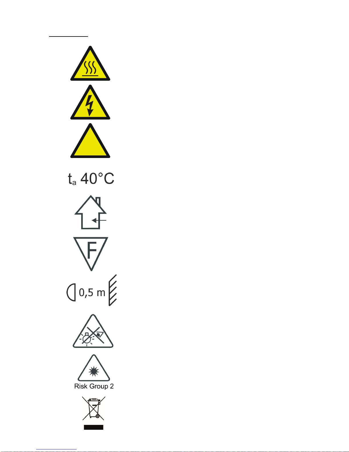
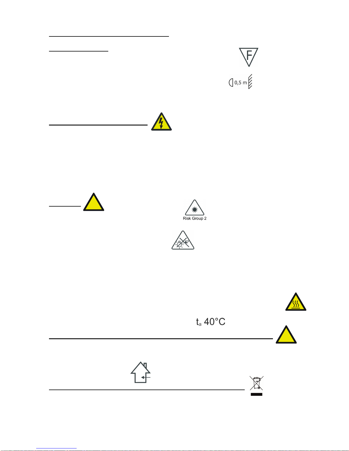
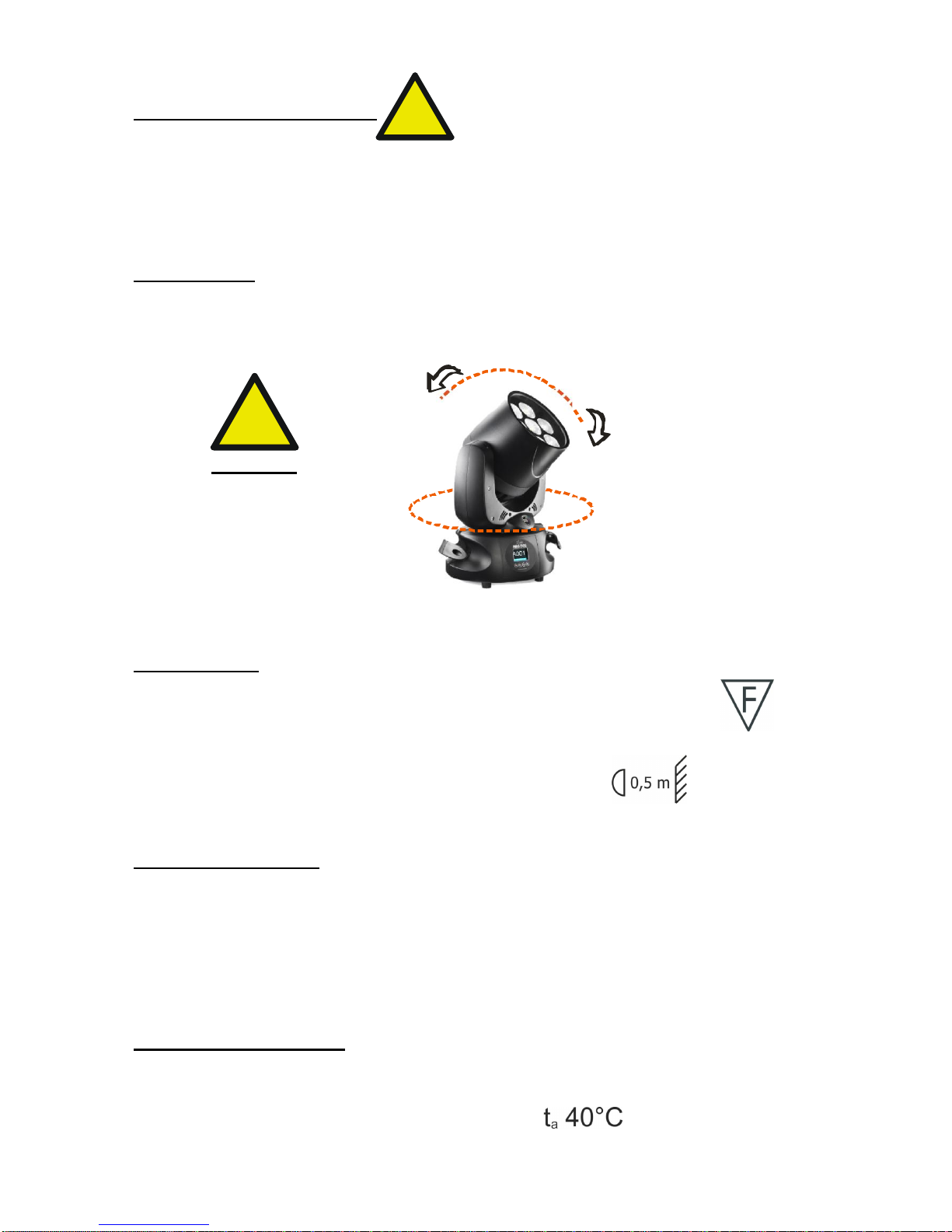
-It is permissible to place the unit on normally flammable surfaces.
Suitable for mounting on normally flammable materials surfaces greater than 200°C
with some combustion time lag.
-Minimum distance from the closest illuminable surface: 0,5 m.
-Replace any blown or damaged fuses only with those of identical value (3.15AT).
Refer to the wiring diagram if there is any doubt.
-Connect the projector to mains power via a thermal magnetic circuit breaker.
7.2 Prevention of electric shock:
-High voltage is present inside the unit. Unplug the unit prior to performing any
function which involves touching the inside of the moving head.
-The level of technology inherent in the NICK NRG 501 requires the assistance of
specialised personnel for all servicing.
Please refer to an authorised DTS service centre.
-A good earth connection is essential for proper functioning of the projector.
-Never connect the unit without proper earth connection.
-The fixture should be located in places with a good air ventilation.
7.3 Safety:
-Risk Group 2 product according to EN 62471.
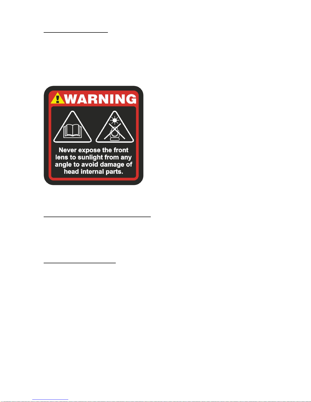
CAUTION. Do not look directly into the light output. May be harmful to the eyes and
skin.
-Do not stare at the operating light source.
-The light source contained in this luminaire shall only be replaced by the
Manufacturer or his service agent or a similar qualified person.
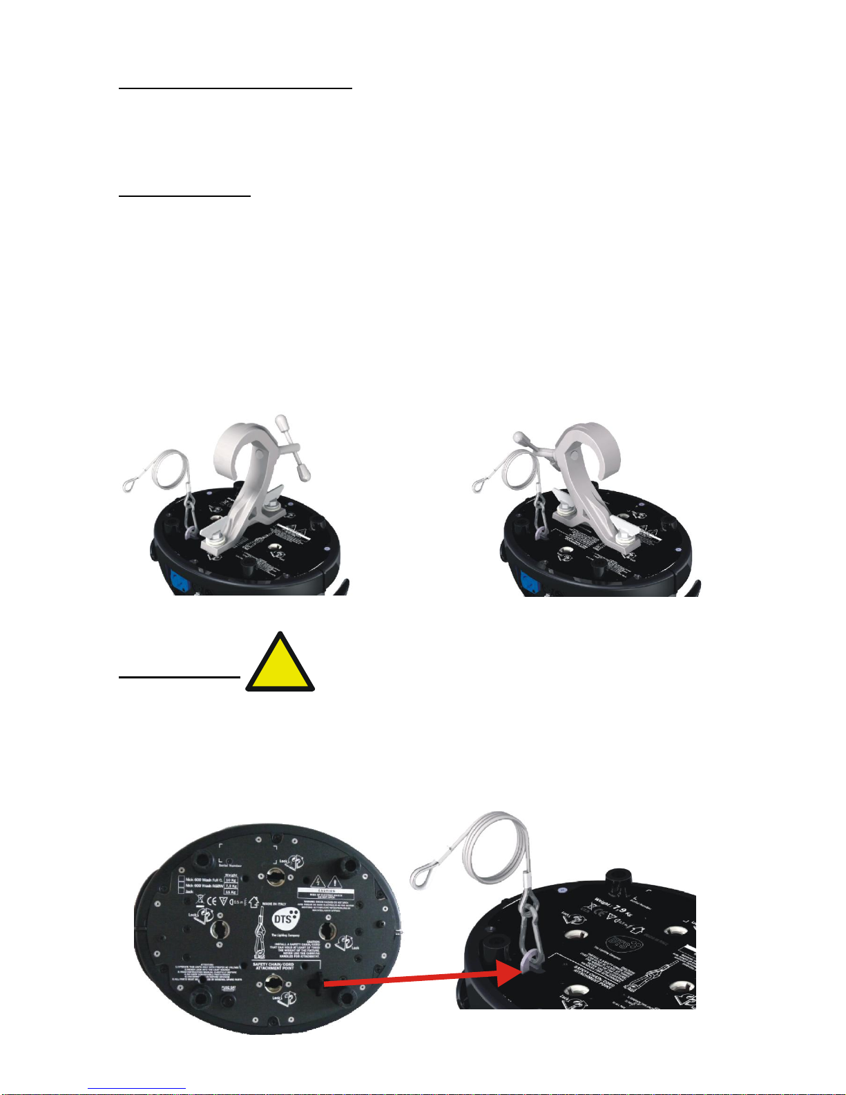
-The projector should always be installed with bolts, clamps and other tools that are
capable of supporting the weight of the unit.
-Always use a second safety cable to sustain the weight of the unit in case of the
failure of the main fixing point.
-The external surface of the unit, at various points, may exceed 50°C. Never handle
the unit until at least 5 minutes have elapsed since the projector was turned off.
-Never install the fixture in an enclosed area lacking sufficient air flow.
The ambient temperature should not exceed 40°C.
7.4 Level of protection against the penetration of solid and liquid objects:
-The projector is classified as an ordinary appliance and its protection level against the
penetration of solid and liquid objects is IP 20.
Suitable for indoor use only.
7.5 Waste Electrical and Electronic equipment (WEEE) directive:
-The machine, accessories and packaging should be sorted for environmetal-friendly
Recycling.
For EC countries: according to the European Directive 2012/19/EC for Waste
Electrical and Electronic Equipment and its implementation into national right,
luminaires that are no longer usable must be collected separately and disposed of in
an environmentally correct manner.
!
!

9
8- VOLTAGE AND FREQUENCY
NICK NRG 501 operates at 100-240Vac 50-60 Hz.
9- INSTALLATION
NICK NRG 501 may be either floor or ceiling mounted.
For floor mounting installations, the NICK NRG 501 is supplied with four rubber
mounting feet on the base.
For ceiling mounted installations, we reccomend the use of appropriate clamps to fix
the unit to the mounting surface.
The supporting structure from which the unit is hung should be capable of bearing the
weight of the unit, as should any clamps used to hung it. The structure should also be
sufficiently rigid so as not to move or shake whilst the NICK NRG 501 is moving.
Four 1/4 turn Fast Locks connections placed in the base of the unit allow to hang the
NICK NRG 501 by using the Fast Lock “C” clamps provided in the box.
9.1- Safety cable
We recommend the use of a safety cable or chain connected to the NICK NRG 501
and to the suspension truss in order to avoid the fixture accidentally falling should the
main fixing point fail.
Make sure that the iron cable or chain can bear the weight of the entire unit.
You may attach the safety chain/cord to the attachment point (A) located on the base
of the fixture, as shown in the picture below.
!
SAFETY CHAIN/CORD
ATTACHMENT POINT
A

10
9.2 Protection against liquids
The projector contains electric and electronic components which should under no
circumstances come into contact with oil, water or any other liquid.
The proper unit functioning would be compromised should this occur.
9.3- Movement
Pan: limitless rotation, in both directions; Tilt 217°.
Do not place any obstructions in the path of the projector's movement.
WARNING
Do not place any object in the
path of the projector’s
movement
9.4- Risk of fire
Each fixture produces heat and must be installed in a well-ventilated place.
It is permissible to place the unit on normally flammable materials surfaces.
Suitable for mounting on normally flammable materials surfaces greater than 200°C
with some combustion time lag.
Minimum distance from the object being illuminated is 0,5 m.
9.5- Forced ventilation
You will note, on inspection, that the unit features various air inlets and cooling fans.
These should, under no circumstances, be blocked or obstructed whilst the projector is
in operation. Doing so could cause the fixture to seriously overheat thereby
compromising its proper operation.
9.6- Ambient temperature
The projector should never be installed in places that lack a constant air flow.
The ambient temperature should not exceed 40°C.
!
!
540°
270° 270°
FPR
217°

11
10- MAINS CONNECTION
NICK NRG 501 operates at 100-240Vac 50-60 Hz.
Prior to connecting the unit to your mains supply, ensure that the model in your
possession correctly matches the mains supply available.
For connection purposes, ensure that your plug is capable of supporting 1 amp
at 230Vac or 2 amps at 90Vac each unit connected.
Strict adherence to regulatory norms is strongly recommended.
MAINS OUTPUT 100-240Vac 50-60 Hz (16A Max)
max 16 NICK NRG 501 units @ 230Vac
max 8 NICK NRG 501 units @ 90Vac
MAINS INPUT 100-240Vac 50-60 Hz
FUSE 3,15AT
10.1- Protection
The use of a thermal magnetic circuit breaker is recommended for each NICK NRG
501.
!

12
11- DMX SIGNAL CONNECTION
The unit operates using the digital DMX 512 signal.
Connection between the mixer and the projector or between projectors must be carried
out using a two pair screened ø 0.5 mm cable and a XLR 5 or 3 pins connector.
Ensure that the conductors do not touch each other.
Do not connect the cable ground to the XLR chassy.
The plug housing must be isolated. Connect the mixer signal to the DMX IN projector
plug and connect it to the next projector by connecting the DMX OUT plug on the first
projector to the DMX IN plug of the second one.
This way, all the projectors are cascade connected.
NB. If the display showing the DMX address flashes, then one of the following errors
has occurred:
- DMX signal not present
- DMX address not valid
- DMX reception problem
For Installations where long distance DMX cable connections are needed, we suggest
to use a DMX terminator.
The DMX terminator is a male XLR 3-5 pins connector with a 120 ohm resistor
between pin 2 and 3.
The DMX terminator must be plugged into the last unit (DMX out panel connector) of
the DMX line.
PLACE A 120 OHM RESISTOR BETWEEN PIN 2
AND 3 OF A MALE XRL CONNECTOR AND PLUG IT
INTO THE DMX OUT PANEL CONNECTOR OF THE
LAST UNIT CONNECTED TO THE DMX LINE
1
2
3
5
4
OUT
120 ohm
PIN 3
PIN 2
1=GND
2=DATA-
3=DATA+
CONTROLLER
S T A N D A R D
D M X 5 1 2

13
11.1-DMX Addresses
NICK NRG 501 can be controlled with 20 DMX channels.
In order to use the unit in 20 channels, set the following addresses on the mixer:
Projector 1 A001
Projector 2 A021 If you want to select the next projector, just add “20”
Projector 3 A041
….. A….
projector 6 A101
11.2-Selecting the DMX address
1) Press the UP-DOWN key until you reach the required DMX channel. The numbers
on the display will start to flash (but the new DMX address hasn't yet been set).
2) Press ENTER to confirm your selection. The numbers on the display will stop
flashing and the projector is now setted to the new DMX address.
TRICKS:
if you keep pushed the UP or DOWN keys, the channels are calculated more quickly
and you get a faster selection.
12- FIRMWARE UPDATING
To update the firmware release of the NICK NRG 1201 you need:
- DTS Dongle Firmware Uploader (code 03.LA.206).
- “DTS Firmware Upgrade Utility v.2.02” program installed on PC.
- Latest firmware release available for NICK NRG 1201 unit.
Updating the firmware release.
Please follow the procedure below to perform the update:
1. Connect the DTS Dongle Firmware Uploader to a spare USB port on the PC.
2. Connect the unit DMX input to the DTS Dongle Firmware Uploader DMX output with
a standard DMX cable and turn ON the unit.
3. Send the new firmware release into the unit by using “DTS Firmware Upgrade
Utility v.2.02” program. At the end of the procedure, the unit will reset.
For more information please refer to an authorised DTS service centre.

14
13- DISPLAY FUNCTIONS
DISPLAY FUNCTIONS
The NICK NRG 501 display panel shows all the available functions . Using these
functions, it is possible to change some of the parameters and add some functions.
Changing the DTS setting can vary the functions of the unit so that it does not
respond to the DMX 512 used to control it. Carefully follow the instructions below
before carrying out any variations or selections.
NOTE: the symbol shows which key has to be pushed to obtain the desired
function.
FIRMWARE RELEASE
1.44
RDM Device Model ID
0x0D1B
DMX Personality ID
0x01 “20CH With FAR”
MENU
ENTER DOWN
UP
DISPLAY

15
13- DISPLAY FUNCTIONS
Display
DISPLAY POSITION / STAND-BY
Display Position:
Reverses display's reading depending on
the mounting position
(on the ground or suspended).
Display Stand-by:
To turn off the display (after 5 seconds)
or leave it always on.
DMX Set
DMX MODE / MACRO / DIMMER DELAY
DMX Mode
20 channels
Up-Down
Menu
Up-DownENTER
ENTER
ENTER
Up-Down
Menu
Up-DownENTER
ENTER
MENU ENTER DOWN UP
AA
DISPLAY
MENU ENTER DOWN UP
OFF
DISPLAY
POSITION
STANDBY
MACRO
STD = Standard mode
enabled (Default)
EXT = Extended; enable
rainbow effects on Macro
channel (DMX ch 16)
MACRO
Macro Mode:
STD = Standard (Default)
EXT = Extended; enable rainbow
effects on Macro channel (DMX ch 16)
Display Position
AA = ON THE GROUND
(Default)
VV = SUSPENDED
Display Standby
OFF = Display Standby
disabled (Default)
ON = Display goes OFF
after 5 seconds
DMX Mode
20 channels
DIMMER DELAY
Range: OFF / 0.1 - 2.0 s
Default = OFF (No Delay)
DIMMER DELAY
Dimmer channel reaction to DMX.
Range: OFF / 0.1 - 2.0 s
Default: OFF
MENU ENTER DOWN UP
20 ch
DMX SET
DMX MODE
MENU ENTER DOWN UP
20CH With FAR
DMX SET
DMX MODE
MENU ENTER DOWN UP
20 ch
DMX SET
DMX MODE
MENU ENTER DOWN UP
STD
DMX SET
MACRO
MENU ENTER DOWN UP
20 ch
DMX SET
DMX MODE
MENU ENTER DOWN UP
OFF
DMX SET
DIMMER DELAY
ENTER
ENTER

16
13- DISPLAY FUNCTIONS
LED
SMOOTH VALUE
This menu allows to select the value
of the delay (in milliseconds) for
RGBW and Dimmer channels
reaction to DMX or Program
variation.
OFF = Instant response (default)
1 = 50 ms smooth response
20 = 1000 ms smooth response
GAMMA CORRECTION
This menu allows to select
between Linear current output
or Quadratic current output for LEDs
Default = Quadratic
OUTPUT FREQUENCY
This menu allows to adjust
the PWM frequency value (Hz)
in order to reduce flickering in
the process of your camera
recordings
BOOST
This menu allows to increase
the LED’s current from 70% to 100%
to 1000 mA
CTC COMPATIBILITY
This menu allows to have the same
“Whites” color temperature on the DMX
channel 15 “CTC” between NICK NRG 501
and other DTS range LED units.
Up-Down
Menu
Up-DownENTER
ENTER
CTC COMPATIBILITY
Default = OFF
SMOOTH
Range = OFF / 1- 20
Default = OFF
GAMMA CORRECTION
Linear = Linear current
output
Quadratic = Linear light
output
(default)
OUTPUT FREQUENCY
Range = 610 Hz –20 KHz
Default = 610 Hz
BOOST
Default = ON
MENU ENTER DOWN UP
20 ch
DMX SET
DMX MODE
MENU ENTER DOWN UP
QUAD
LED
GAMMA CORR.
MENU ENTER DOWN UP
20 ch
DMX SET
DMX MODE
MENU ENTER DOWN UP
610
LED
OUTPUT FREQ.
MENU ENTER DOWN UP
20 ch
DMX SET
DMX MODE
MENU ENTER DOWN UP
ON
LED
BOOST
MENU ENTER DOWN UP
20 ch
DMX SET
DMX MODE
MENU ENTER DOWN UP
OFF
LED
SMOOTH
MENU ENTER DOWN UP
20 ch
DMX SET
DMX MODE
MENU ENTER DOWN UP
OFF
LED
CTC COMPAT.

17
13- DISPLAY FUNCTIONS
AUTO
AUTOMATIC MODE
Automatic demo game
without DMX controller
STEP 01/16
Chase with 16 steps previously
created in REC MODE
Speed time, Wait time, Dimmer, Pan,
Tilt and Zoom values selectable by user.
PERSONAL COLOURS
RGBW, Dimmer, Shutter, Pan, Tilt and
Zoom values selectable by user.
RAINBOW
Rainbow colours effect.
Speed time, Dimmer, Shutter, Pan,
Tilt and Zoom values selectable by user.
FIXED COLOURS
Sixteen Colour Macros as
on “MACRO” channel.
Dimmer, Shutter, Pan, Tilt and
Zoom values selectable by user.
WHITE MACROS
Sixteen macros for White
color (from 2700K to 8000K)
Dimmer, Shutter, Pan, Tilt and
Zoom values selectable by user.
Up-Down
Menu
Up-DownENTER
ENTER
MENU ENTER DOWN UP
20 ch
DMX SET
DMX MODE
MENU ENTER DOWN UP
AUTO
SURE?
Menu - NO
Enter - YES
MENU ENTER DOWN UP
20 ch
DMX SET
DMX MODE
MENU ENTER DOWN UP
01/16
AUTO-PROGRAM
STEP
MENU ENTER DOWN UP
20 ch
DMX SET
DMX MODE
MENU ENTER DOWN UP
120
AUTO-PERS.COL.
RED
MENU ENTER DOWN UP
20 ch
DMX SET
DMX MODE
MENU ENTER DOWN UP
0010
AUTO-RAINBOW
SPEE
MENU ENTER DOWN UP
20 ch
DMX SET
DMX MODE
MENU ENTER DOWN UP
1
AUTO-WHITE
WHITE NO.
20 ch
DMX SET
DMX MODE
1
AUTO-FIXED COL.
COLOR
MENU ENTER DOWN UP
MENU ENTER DOWN UP
By setting all the units
connected to the MASTER
to DMX address 1,
them will be synchronized
with the Master unit
following the chase
selected on it, including
TIME, WAIT, Pan&Tilt and
Zoom position of the
MASTER unit.

18
13- DISPLAY FUNCTIONS
SLAVE
SLAVE MODE SETTING
This menu allows to set the
NICK NRG 501 as slave unit.
DMX signal must be present
from MASTER unit (set in
AUTO MODE) in order to ran
the units in SLAVE mode.
By setting all the SLAVE units
connected to the MASTER, to
DMX addess 1, them will be
synchronized with the Master
unit following the chase
selected on it, but running their
own Pan&Tilt and Zoom position.
Up-Down
Menu
Up-DownENTER
ENTER
MENU ENTER DOWN UP
20 ch
DMX SET
DMX MODE
MENU ENTER DOWN UP
128
SLAVE
PAN
MENU ENTER DOWN UP
20 ch
DMX SET
DMX MODE
MENU ENTER DOWN UP
SLAVE
SURE?
Menu - NO
Enter - YES
MENU ENTER DOWN UP
20 ch
DMX SET
DMX MODE
MENU ENTER DOWN UP
128
SLAVE
TILT
MENU ENTER DOWN UP
20 ch
DMX SET
DMX MODE
MENU ENTER DOWN UP
0
SLAVE
ZOOM
The SLAVE unit receive DMX
signal from the MASTER unit.
By setting all the SLAVE units
connected to the MASTER, to
DMX address 1, them will be
synchronized with the Master
unit following the chase selected
on it, but running their own
Pan&Tilt and Zoom position.

19
13- DISPLAY FUNCTIONS
WIRELESS
WIRELESS DMX
Wieless DMX enabled / disabled.
By activating WDMX MODE, it will
be possible to control NICK NRG
501 via D.T.S. ANTENNA Wireless
DMX Transmitter (cod. 03.E1271 –
03.E1296 –03.E12101).
Wireless DMX Receiver Kit
(Cod. 03.LA.126) on NICK NRG
501 is available on request.
Logging on NICK NRG 501 (WIRELESS DMX must be enabled on the unit).
To log on the NICK NRG 501 in the WIRELESS system simply press and quickly release the function
button on the transmitter .
The transmitter will start flashing rapidly red/green scanning for new free receivers / NICK NRG 501
units. When a NICK NRG 501 logs on to the transmitter the LINK green light on transmitter starts to
flash rapidly.
After approximately 10 seconds the transmitter will jump back to normal mode and continue transmitting
data. The NICK NRG 501 now try to synchronize to the transmitter.
When synchronized to the transmitter, 2 different modes are possible:
1. Antenna transmitter has detected and transmits a DMX signal, in this mode a solid green light is seen
on the transmitter and solid display is seen on NICK NRG 501.
2. No DMX signal connected, the Antenna transmitter will flash red/green; display blinking on NICK
NRG 501.
To log off NICK NRG 501 from a transmitter simply select UNLINK function under WIRELESS DMX
MENU and press ENTER.
When NICK NRG 501 is logged off the display is blinking, meaning its available for log in on a new
transmitter.
Logging out a NICK NRG 501.
Select UNLINK function under WIRELESS DMX MENU and press ENTER.
When NICK NRG 501 is logged off the display is blinking, meaning its available for log in on a new
transmitter.
Logging out all NICK NRG 501 linked to a transmitter.
Press and hold the function button of the transmitter for about 3 seconds. When the display is blinking
on NICK NRG 501, it mean that the units are logged out.
Transmitter, Status LED.
Flashing red/green, no dmx connected.
Solid green, dmx signal detected and transmitted.
Fast flashing red/green, log in mode (every free NICK NRG 501 unit, not logged in to any other
transmitter, will be logged on)
NICK NRG 501 Status.
Display blinking, not logged on to a transmitter (free).
Solid display, logged on to a transmitter and receiving dmx data.
MENU ENTER DOWN UP
20 ch
DMX SET
DMX MODE
MENU ENTER DOWN UP
WIRELESS
UNLINK
20 ch
DMX SET
DMX MODE
OFF
WIRELESS
SELECTION
MENU ENTER DOWN UP
MENU ENTER DOWN UP
20 ch
DMX SET
DMX MODE
ON
WIRELESS
SELECTION
MENU ENTER DOWN UP
MENU ENTER DOWN UP
Up-Down
Menu
Up-DownENTER
ENTER
ENTER
ENTER
WIRELESS DMX SYSTEM
DISABLED (Default)
WIRELESS DMX SYSTEM
ENABLED
UNLINK = LOG OUT

20
13- DISPLAY FUNCTIONS
EMERGENCY
EMERGENCY
Emergency operating mode.
By setting Emergency mode, it will
be possible to select one of the
16 preprogrammed WHITE cues
that will then ran if DMX signal is
missing or not available.
Useful for Emergency EXIT
illumination on public areas.
Dimmer level, Pan&Tilt and
Zoom values selectable by user.
MENU ENTER DOWN UP
20 ch
DMX SET
DMX MODE
MENU ENTER DOWN UP
OFF
EMERGENCY
SELECTION
MENU ENTER DOWN UP
20 ch
DMX SET
DMX MODE
MENU ENTER DOWN UP
1
EMERGENCY
WHITE
MENU ENTER DOWN UP
20 ch
DMX SET
DMX MODE
MENU ENTER DOWN UP
255
EMERGENCY
DIMMER
MENU ENTER DOWN UP
20 ch
DMX SET
DMX MODE
MENU ENTER DOWN UP
128
EMERGENCY
PAN
MENU ENTER DOWN UP
20 ch
DMX SET
DMX MODE
MENU ENTER DOWN UP
128
EMERGENCY
TILT
MENU ENTER DOWN UP
20 ch
DMX SET
DMX MODE
MENU ENTER DOWN UP
0
EMERGENCY
ZOOM
MENU ENTER DOWN UP
20 ch
DMX SET
DMX MODE
MENU ENTER DOWN UP
ON
EMERGENCY
SELECTION
Up-Down
Menu
Up-DownENTER
ENTER
EMERGENCY
Disabled = Default
EMERGENCY
Enabled
WHITE (1-16)
Default = WHITE 1
DIMMER
Default = 255
PAN
Default = 128
TILT
Default = 128
ZOOM
Default = 0
Other manuals for NICK NRG 501
1
This manual suits for next models
1
Table of contents
Other DTS Dj Equipment manuals

DTS
DTS SCENA LED 120 HQS User manual

DTS
DTS X BRICK User manual

DTS
DTS XR2000 SPOT CMY User manual

DTS
DTS ALCHEMY 5 User manual

DTS
DTS Wonder D User manual

DTS
DTS MINI BRICK User manual

DTS
DTS SCENA LED 200 Series User manual

DTS
DTS Synergy 5 Spot User manual

DTS
DTS 03.MS014.EBLFP User manual

DTS
DTS NICK NRG 1401 User manual

DTS
DTS XR2000 SPOT CMY User manual

DTS
DTS PROFLO LED 200 CT User manual

DTS
DTS Alchemy 7 User manual

DTS
DTS EUPHONY 3 User manual

DTS
DTS DOCTUS Series User manual

DTS
DTS DELTA 10 F User manual

DTS
DTS Portfolio User manual

DTS
DTS NICK NRG 1401 User manual

DTS
DTS X-BRICK User manual

DTS
DTS Titan HP User manual