4 7117100018L30 1712V002
Important information
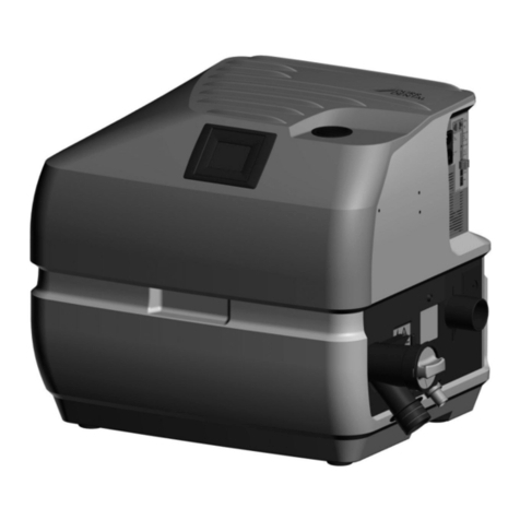
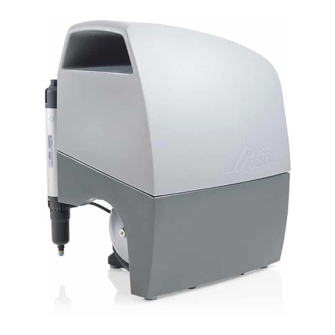
The CAS 1 Combi Separator for KaVo treatment
units must be set up in a defined installation
setup in order to meet the relevant safety stand-
ards� For this reason it must only be installed
in the treatment units that have been designed
and approved for this purpose by KaVo�
KaVo-approved treatment units:
New units delivered from 01/2016 onwards:
E50, E50 Life, E70/E80, E70/E80 Vision, 1058,
1058 Life
Spare parts requirements for old units such as
1078 and 1080 among others�
2.3 Improper use
Any other usage or usage beyond this scope
is deemed to be improper� The manufacturer
accepts no liability for damages resulting from
this� In these cases the user/operator will bear
the sole risk�
The Combi-Separator must only be used to pro-
cess liquids from the oral cavity� It must not be
used for the aspiration of any other substances,
such as dust, sludge, plaster or similar�
Only chemicals and disinfectants that will not
damage the materials, e�g� OrotolPlus or equiv-
alent, may be used�
The unit is not suitable for installation down-
stream of 2 or more workplaces� The max�
water volume of 4�0l/min must not be
exceeded�
The device must not be run in continuous oper-
ation; the braking process after the end of the
run is required in order to keep the centrifuge
drum clean�
The device must not be installed with the drain
higher than the connection piece on the device�
Do not use any risers� All pipes must have a
downward gradient�
Not suitable for wet rooms! Do not use this
device to aspirate flammable or explosive mix-
tures� Do not use the unit in a potentially explo-
sive environment!
2.4 Systems, connection with other
devices
Additional devices connected with medical elec-
trical devices must be proven to conform with
their corresponding IEC or ISO standards� All
configurations must continue to comply with the
standard requirements for medical systems (see
IEC 60601-1-1 or section 16 of the 3rdedition
of IEC60601-1 respectively)�
2 Safety
Dürr Dental has designed and constructed this
device so that when used properly and for the
intended purpose there is no danger to people
or property� Nevertheless, residual risks can
remain� You should therefore observe the follow-
ing notes�
2.1 Intended purpose
The CAS 1 Combi-Separator is designed for
continuous separation of liquids and air and for
separation of amalgam from the entire waste
water from dental treatment units�
2.2 Intended use
Installation in accordance with the requirements
of the water authorities in the German Federal
States or in accordance with local regulations�
In accordance with the installation regulations of
DIBT Berlin�
The CAS 1 Combi-Separator is designed for the
separation of liquids and air as well as for the
separation of amalgam from the waste water
from a single treatment unit in a dry system�
Installation in dental treatment units and in prac-
tice rooms (housing version)� Positioned in the
suction line after the spittoon and manifold�
The minimum volume of waste water that can
be supplied to the unit is 0�1l/min, but must not
exceed 4�0l/min� Here, a separation efficiency
of at least 95%is maintained with amalgam�
A rinsing unit with fresh water can be installed
in the suction line upstream of the Combi-Sep-
arator�
Installation, servicing and repairs must only be
performed by qualified personnel specifically
approved and authorized by Dürr Dental�
The disposable amalgam containers must only
be used once�
For surgical treatments and when the
Airflow is being used, the CAS1 Com-
bi-Separator requires a rinsing unit to be
installed, which feeds a small amount
of water to the device during aspiration�
This thins any liquid (e�g�saliva, blood)
that occurs so it can be transported
more easily�
EN
