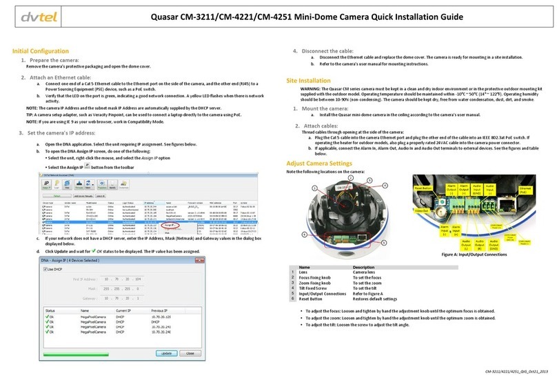
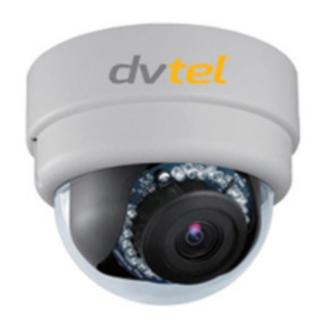
DVTEL Pro Line 9460A User manual

Pro Line 9460A
Vandal Resistant Mini Dome
User’s Manual
October 13, 2008

Copyright © 2008 DVTel Inc.
All Rights Reserved
All text and figures included in this publication are the exclusive property of DVTel Inc., and may not be copied,
reproduced or used in any way without the express written permission of DVTel Inc. Information in this document is
subject to change without notice.
This document also contains registered trademarks and service marks that are owned by their respective companies or
organizations.
Notice
While reasonable effort was made to ensure that the information in this document was complete and accurate at the
time of printing, DVTel Inc. cannot assure the accuracy of such information. Changes and/or corrections to the
information contained in this document may be incorporated into future issues.

i
Table of Contents
Overview . . . . . . . . . . . . . . . . . . . . . . . . . . . . . . . . . . . . . . . . . . 1-1
Technical Support . . . . . . . . . . . . . . . . . . . . . . . . . . . . . . . . . . . . . . . . . . . 1-1
Hardware Products Warranty and Returns Statement . . . . . . . . . . . . . . 1-2
Warranty . . . . . . . . . . . . . . . . . . . . . . . . . . . . . . . . . . . . . . . . . . . . . . 1-2
Warranty Exclusion . . . . . . . . . . . . . . . . . . . . . . . . . . . . . . . . . . . . . . . 1-2
Limitations of Warranty . . . . . . . . . . . . . . . . . . . . . . . . . . . . . . . . . . . . 1-2
Limitations of Liability . . . . . . . . . . . . . . . . . . . . . . . . . . . . . . . . . . . . . 1-3
Configuration and Installation . . . . . . . . . . . . . . . . . . . . . . . . 2-1
Bench Installation of the Pro Line 9460A Mini Dome Cameras . . . . . . . 2-1
Bench Installation . . . . . . . . . . . . . . . . . . . . . . . . . . . . . . . . . . . . . . . . 2-1
Configuring the Mini Dome Camera . . . . . . . . . . . . . . . . . . . . . . . . . . . . . 2-2
Prerequisites . . . . . . . . . . . . . . . . . . . . . . . . . . . . . . . . . . . . . . . . . . . 2-3
Configuring the Mini Dome Camera Parameters . . . . . . . . . . . . . . . . . . . 2-3
To set the parameters of a mini dome camera . . . . . . . . . . . . . . . 2-3
Site Installation of the Pro Line 9460A Mini Dome Camera . . . . . . . . . . 2-5
To install the mini dome camera . . . . . . . . . . . . . . . . . . . . . . . . 2-5
Camera Installation . . . . . . . . . . . . . . . . . . . . . . . . . . . . . . . . . . . . . . . . . . 2-9
Configuring the I/Os . . . . . . . . . . . . . . . . . . . . . . . . . . . . . . . . . . . . . . . . 2-11
Audio . . . . . . . . . . . . . . . . . . . . . . . . . . . . . . . . . . . . . . . . . . . . . . . 2-12
Data Transmission . . . . . . . . . . . . . . . . . . . . . . . . . . . . . . . . . 2-12
Audio Input/Output Types . . . . . . . . . . . . . . . . . . . . . . . . . . . . 2-12
Specifications . . . . . . . . . . . . . . . . . . . . . . . . . . . . . . . . . . . . . 2-12
Alarms . . . . . . . . . . . . . . . . . . . . . . . . . . . . . . . . . . . . . . . . . . . . . . . 2-13
Updating the Firmware . . . . . . . . . . . . . . . . . . . . . . . . . . . . . . . . . . . . . . 2-13
Red/Blue Display . . . . . . . . . . . . . . . . . . . . . . . . . . . . . . . . . . . . . . . . . . . 2-13
Using the Web Interface . . . . . . . . . . . . . . . . . . . . . . . . . . . . . 3-1
Accessing the Web Interface . . . . . . . . . . . . . . . . . . . . . . . . . . . . . . . . . . 3-1
To access the Web interface via the Device Configurator . . . . . . . 3-1
To access the Web interface via a web browser . . . . . . . . . . . . . . 3-2
Using the Web Interface . . . . . . . . . . . . . . . . . . . . . . . . . . . . . . . . . . . . . . 3-3
Web Interface Workspace . . . . . . . . . . . . . . . . . . . . . . . . . . . . . . . . . . 3-3
Setting General Parameters . . . . . . . . . . . . . . . . . . . . . . . . . . . . . . . . . 3-4
To set general parameters . . . . . . . . . . . . . . . . . . . . . . . . . . . . . 3-4
Using the Digital Zoom . . . . . . . . . . . . . . . . . . . . . . . . . . . . . . . . . . . . 3-4
To use the digital zoom . . . . . . . . . . . . . . . . . . . . . . . . . . . . . . . 3-4
Setting Network Configuration Parameters . . . . . . . . . . . . . . . . . . . . . . 3-5
To set the Network configuration parameters . . . . . . . . . . . . . . . 3-5
Setting Serial Port Parameters . . . . . . . . . . . . . . . . . . . . . . . . . . . . . . . 3-6

Pro Line 9460A User’s Manual
ii
To set Serial Port parameters . . . . . . . . . . . . . . . . . . . . . . . . . . . 3-6
Setting Video Profile Parameters . . . . . . . . . . . . . . . . . . . . . . . . . . . . . 3-7
To set the Video Profile parameters . . . . . . . . . . . . . . . . . . . . . . 3-7
Setting Picture Profile Parameters . . . . . . . . . . . . . . . . . . . . . . . . . . . . 3-8
To set the Picture Profile parameters . . . . . . . . . . . . . . . . . . . . . 3-8
Using the CLI . . . . . . . . . . . . . . . . . . . . . . . . . . . . . . . . . . . . . . 4-1
Accessing the CLI . . . . . . . . . . . . . . . . . . . . . . . . . . . . . . . . . . . . . . . . . . . 4-1
To access the CLI via the Device Configurator . . . . . . . . . . . . . . . 4-1
To access the CLI via the Telnet terminal . . . . . . . . . . . . . . . . . . 4-2
Using the CLI . . . . . . . . . . . . . . . . . . . . . . . . . . . . . . . . . . . . . . . . . . . . . . . 4-2
To work with the CLI menu structure . . . . . . . . . . . . . . . . . . . . . 4-3
Setting Serial Port Parameters . . . . . . . . . . . . . . . . . . . . . . . . . . . . . . . 4-3
To set Serial Port parameters . . . . . . . . . . . . . . . . . . . . . . . . . . . 4-3
Setting the Access Management Parameters . . . . . . . . . . . . . . . . . . . . . 4-4
To set Access management parameters . . . . . . . . . . . . . . . . . . . 4-4
Setting the System Status Parameters . . . . . . . . . . . . . . . . . . . . . . . . . 4-5
To set System status parameters . . . . . . . . . . . . . . . . . . . . . . . . 4-5
Setting Network Parameters . . . . . . . . . . . . . . . . . . . . . . . . . . . . . . . . 4-6
To set the Network parameters . . . . . . . . . . . . . . . . . . . . . . . . . 4-6
Setting the Ethernet Communication Parameters . . . . . . . . . . . . . . . . . . 4-7
To set the Physical Mode parameters . . . . . . . . . . . . . . . . . . . . . 4-7
Setting Advanced Parameters . . . . . . . . . . . . . . . . . . . . . . . . . . . . . . . 4-8
To access the Advanced menu . . . . . . . . . . . . . . . . . . . . . . . . . . 4-8
To set the Video menu parameters . . . . . . . . . . . . . . . . . . . . . . . 4-8
To set the Video Status menu parameters . . . . . . . . . . . . . . . . . 4-11
To set the Serial Port Status parameters . . . . . . . . . . . . . . . . . . 4-12
To set the VSIP menu parameters . . . . . . . . . . . . . . . . . . . . . . 4-12
To view and reset the VSIP Statistics menu parameters . . . . . . . 4-13
To set the Audio menu parameters . . . . . . . . . . . . . . . . . . . . . . 4-13
To view the Test and Debug menu parameters . . . . . . . . . . . . . 4-15
To set the Outputs Control menu parameters . . . . . . . . . . . . . . 4-15
To set the System Time menu parameters . . . . . . . . . . . . . . . . 4-15
To view and reset the System Time Stats menu parameters . . . . 4-16
To set the HTTP parameters . . . . . . . . . . . . . . . . . . . . . . . . . . 4-16
To set the Quality of Service parameters . . . . . . . . . . . . . . . . . . 4-16
Factory Default Configuration . . . . . . . . . . . . . . . . . . . . . . . . .A-1
DHCP Support and APIPA . . . . . . . . . . . . . . . . . . . . . . . . . . . .B-1
Technical Specifications . . . . . . . . . . . . . . . . . . . . . . . . . . . . . .C-1
MPEG License Statement . . . . . . . . . . . . . . . . . . . . . . . . . . . . .D-1
1-1
Overview 1
The Pro Line 9460A is a highly compact, dual-stream 4CIF mini dome camera for video monitoring
and surveillance over IP networks. It is built on open standards to provide long-term investment
protection.
The Pro Line 9460A mini dome camera can be used with the iSOC NVMS applications. Furthermore, it
enables configuration and video viewing from web browsers and configuration via Telnet.
The Pro Line 9460A mini domes come pre-configured with a choice of camera modules. These
camera modules are fully interchangeable in the dome housing.
Technical Support
If you encounter any problems, please contact DVTel Technical Support. DVTel Technical Support can

Pro Line 9460A User’s Manual
1-2
Hardware Products Warranty and
Returns Statement
Warranty
DVTel warrants, to the original purchaser, a DVTel branded HARDWARE PRODUCT furnished will
generally function in accordance with DVTel's written product specifications in effect at the time of
shipment, and that, under normal use, it will be free from defects in materials and workmanship, for
a period of two years from the date of delivery as evidenced by the DVTel packing slip or other
transportation receipt. DVTel does not warrant that PRODUCTS are error free. DVTEL does not
warrant or guarantee the use or compatibility of the camera with any specific video management
software product.
The warranty becomes void if the product is altered in any way.
DVTel's responsibility under this warranty shall be to repair or replace, at its option, defective work or
returned parts, with transportation charges for the returned equipment's shipping to DVTel's repair
center paid for by the buyer and return shipping charges covered by DVTel. If DVTel determines that
the Product is not defective within the terms of the warranty, the buyer shall pay all handling and
transportation costs. If a materials and workmanship defect appears within such warranty period,
Customer may return the defective product for replacement with the same or a later model that
performs substantially the same function as the unit being replaced or for repair, at DVTel's option.
Warranty Exclusion
The Warranty for equipment shall become void if a hardware PRODUCT has been subjected to water,
excessive dust, fire, excessive heat, chemicals, acids, solvents, physical attack, voltage surges,
brownouts, or similar circumstances which ordinarily may damage electrical components, or by
repairs or modifications made or attempted to be made to components other than by DVTel or under
its direction. Products showing damage by misuse or abnormal conditions of operation, or which
have been modified by the buyer or repaired or altered outside of DVTel's repair center without
specific authorization from DVTel shall be excluded from this warranty.
DVTel reserves the right to make changes to its specifications from time to time. DVTel warrants that
it is empowered to grant the rights granted herein.
Limitations of Warranty
DVTEL MAKES NO OTHER REPRESENTATIONS OR WARRANTIES, EXPRESS OR IMPLIED. Since DVTel
has no control over conditions of use, no warranty is made or implied as to suitability for customer's
intended use. There are no warranties, expressed or implied, except as stated herein. This limitation
on warranties shall not be modified by verbal representations.

Overview
1-3
Limitations of Liability
With the exception of the terms and conditions stated in this document, DVTEL SHALL NOT BE HELD
TO ANY LIABILITY WITH RESPECT TO ANY CLAIM BY CUSTOMER OR A THIRD PARTY ON ACCOUNT
OF, OR ARISING FROM, THE USE OF ANY PRODUCT. IN NO EVENT SHALL DVTEL BE LIABLE UNDER
ANY CIRCUMSTANCES FOR SPECIAL, INDIRECT, PUNITIVE OR CONSEQUENTIAL DAMAGES OF ANY
NATURE WHATSOEVER (WHETHER ARISING OUT OF CONTRACT, STRICT LIABILITY, OR
OTHERWISE), INCLUDING WITHOUT LIMITATION ANY LOST REVENUES OR PROFITS OF
CUSTOMER, OR LIABILITY TO CUSTOMER OR THIRD PARTIES RESULTING FROM OR ARISING OUT
OF A BREACH OF THIS AGREEMENT AND/OR ANY FAILURE OF THE PRODUCT(S), WHETHER OR
NOT DVTEL HAS BEEN ADVISED OF THE POSSIBILITY OF SUCH DAMAGES. IN ANY EVENT, DVTEL'S
LIABILITY SHALL NOT EXCEED THAT AMOUNT THAT CUSTOMER ACTUALLY PAID FOR THE
PRODUCT GIVING RISE TO THE LIABILITY.
Equipment shipped ex works by DVTel shall become the property of buyer upon transfer to the
common carrier. The buyer is responsible for communicating directly with the carrier and immediately
requesting carrier's inspection upon evidence of damage in shipment.
The buyer must obtain a Return Materials Authorization (RMA) number and shipping instructions from
DVTel prior to returning any product under warranty. Do not return any DVTel product to the repair
center until RMA and shipping instructions are received.

Pro Line 9460A User’s Manual
1-4

2-1
Configuration and Installation 2
The following procedures are performed to configure and set up the mini dome camera:
•
Bench Installation of the Pro Line 9460A Mini Dome Cameras
•
Configuring the Mini Dome Camera
•
Site Installation of the Pro Line 9460A Mini Dome Camera
•
Camera Installation
•
Configuring the I/Os
•
Updating the Firmware
•
Red/Blue Display
Bench Installation of the Pro Line 9460A
Mini Dome Cameras
The Pro Line 9460A Series Mini-Dome contain the following parts
•Camera Module/Gimbal assembly - (PN DVT-FDC-xx)
•Camera Housing – (PN DVT-VDHD or DVT-VDHDT)
•Surface ring if applicable
•Power and alarm cables
•Rubber cable gland
•Screws packages
•Mounting template
•Installation Guides
—Mini-Dome Install Guide
—Camera/WDR Programming Guide
—Connections/Latitude Setup Guide
All other mounting hardware must be provided by the installer. The power source options - 12VDC,
1A (UL, CE approved) or 802.3af compliant power source are sold separately or provided by the
installer.
Bench Installation
Connect the vandal dome either to 12V DC power source or an 802.3af compliant Power Over
Ethernet (POE) switch or mid span. If connecting to a 12V DC supply use the appropriate accessory
cable and plug into the power connector.

Pro Line 9460A User’s Manual
2-2
The following shows the 12VDC connection options:
Figure 2-1: 12VDC Connection Options
If using PoE, just connect to the RJ45 as shown:
Figure 2-2: RJ45 Connection Options
Configuring the Mini Dome Camera
Upon receiving Pro Line 9460A mini dome camera, its basic parameters, such as the IP address, need
to be configured.
To configure the device, you need the Device Configurator. This application is provided along with the
mini dome camera. The Device Configurator is accessible via the Unified Configurator from the iSOC

Configuration and Installation
2-3
NVSM 5.3 AdminCenter. In addition, the Device Configurator is an executable file that is compressed
in a .rar file along with the following additional files:
•Configurator.ini
•CRC.dll
•IPAddressControlLib.dll
•VsipApi.dll
Once you extract all the files contained in the .rar file to the hard disk of your computer, and open the
Device Configurator
executable file, the application is ready to use.
Prerequisites
The following hardware and software requirements must be fulfilled to configure Pro Line 9460A mini
dome cameras:
•Windows XP
•An Ethernet network card
Configuring the Mini Dome Camera Parameters
When installing Pro Line 9460A mini dome cameras, you have to change their IP address to ensure
the compatibility with an existing network. The primary default IP address of the mini dome camera is
created using the APIPA addressing scheme and is in the range 176.(a+16).bc.de, based upon the
hex to decimal conversion of the MAC address of the individual device:
nn-nn-nn-na-bc-de
. When
resetting the mini dome camera to the factory default values, the IP will change back to the address
created by the APIPA.
After discovering the mini dome camera on the IP network, its network configuration parameters
need to be set. Mini dome cameras that reside on the same network must have unique IP addresses.
To set the parameters of a mini dome camera
1. In a lab, unpack the mini dome camera and place it on a table.
2. Connect the mini dome camera to a power supply or a POE power source.
3. Connect the mini dome camera in one of the following ways:
—When using an external power supply (12VDC, 1A - sold separately), establish the Ethernet
connection by plugging a cable (straight-through or crossover) into the LAN 10/100
connector on the back of the mini dome camera.
A crossover cable should be used to directly connect the device to a computer; a straight-
through cable should be used to integrate the mini dome camera on a network.
—When using the POE, the Ethernet connection is automatically established after being
connected to the power supply.
For more detailed information and illustrations, see the relevant
Quick Installation Guide
.
4. If you are using the regular power supply, connect the power supply as described in the relevant
Quick Installation Guide
.

Pro Line 9460A User’s Manual
2-4
For any other power supply, refer to the manufacturer documentation for the proper wiring
scheme.
The mini dome camera is powered up as soon as power is provided.
5. Start the
Device Configurator
by double-clicking the
Configurator.exe
file or by accessing the
iSOC NVSM 5.3 AdminCenter and selecting Pro Line A in the Unified Configurator.
The
Pro Line A Device Configurator
appears.
Figure 2-3: Pro Line A Device Configurator
6. Once the
Device Configurator
appears, the Discovery process starts automatically.
The discovered mini dome cameras appear in the
Unit Management
pane
7. In the
Unit Management
pane, select the desired mini dome camera.
Once a mini dome camera is selected, the Network configuration pane is enabled.
8. In the
IP address
field, enter the IP address of the mini dome camera.
9. In the
Subnet Mask
field, enter the subnet mask of the mini dome camera.
10. In the Gateway IP field, enter the gateway IP address of the mini dome camera.
11. Click Update.
The mini dome camera will reset and the new network configuration parameters will appear in
the
Unit Management
pane. The initial configuration of the mini dome camera is now complete.
You can perform further configuration with the Telnet and web interface.

Configuration and Installation
2-5
Site Installation of the Pro Line 9460A
Mini Dome Camera
After the mini dome camera is configured successfully, it can be installed in its final location.
Use the provided mounting template to mark out and create the necessary holes in the mounting
surface.
To install the mini dome camera
1. Use the provided mounting template to mark out and create the necessary holes in the mounting
surface.
Table 2-1: Mount Types
2. Decide which entry point in the housing will be used to route wires and remove the appropriate
conduit plug.
If installing in an interior location and conduit will not be used, be sure to install a rubber cable
gland in the opening before passing the wires through the opening.
3. Mount the camera using one of the following methods — Recessed or Surface.
Mount Type Instructions
Surface Create four holes at the template position marked (T1). (Use four
No12) fixing screws and wall plugs. For addition support there are
3 more mounting holes in the surface ring (T4) that may also be
used.
Recessed Create an aperture in the mounting surface to a diameter of
139mm as indicated by the (T2) circle.

Pro Line 9460A User’s Manual
2-6
Recess Mount
The Pro Line 9460A units are provided with fold out wings for quick and easy installation into a
ceiling without the need for a special mounting kit. To use the fold out wings, turn silver-colored
screws clockwise to first extend the locking arms and then tighten them against the mounting
surface. Tighten the screws sufficiently to compress the o-ring moisture seals located underneath
the screw heads, however: DO NOT OVERTIGHTEN.
Note:
For outdoor installations or wet environments always install the large rubber gasket to seal the
dome properly to maintain the IP rating.
If mounting in a drop ceiling a backer plate may be needed depending on the integrity of the
ceiling tile. You could also attach a pipe hanger to the tapped hole in the bottom of the housing
for additional support.

Configuration and Installation
2-7
Surface Mount
You have two options when using the surface ring, it either needs to be mounted before the base
is installed (only required if using the 3 addition mounting locations on the surface ring) or you
insert the dome housing into the surface ring before mounting with the screw locations shown
below.
4. When mounting make sure you install the large rubber gasket between the housing and the
surface ring or if recessed mounting between the housing and mounting surface.
5. Insert the network cable and optional power cable through one of the conduit entry points and
connect them to the dome as described under bench installation.
6. If running conduit to the unit you will need to install a 3” threaded pipe nipple through the
surface ring and thread this into the housing. Use appropriate sealing agent on the connection to
maintain the IP rating of the housing.
7. If applicable, connect the audio and alarm inputs/outputs to the 8 wire cable located in the lower
part of the housing. Refer to the following table to determine which wires correspond to the
inputs outputs relevant to your installation.

Pro Line 9460A User’s Manual
2-8
Alarm and Audio Connections
The Pro Line 9460A provides an accessory cable to easily connect audio input and output, alarm
inputs and relay output.
Note:
•
The top of the camera is omitted from the picture to clearly show the alarm cable.
•
When connecting alarms or audio, snap on the EMI suppression bead, provided in the accessory
kit, over the factory installed cable assembly to ensure emissions compliance (FCC part 15,
subpart B, class A).
•
The mini dome cameras are provided with Ethernet Jumper cable for initial configuration. For
permanent installation use RJ45 CAT-5 shielded cable and snap on the EMI suppression bead
provided in the accessory kit to ensure emissions compliance (FCC part 15, subpart B, class A).

Configuration and Installation
2-9
Table 2-2: Input and Output Wire Setup
Camera Installation
1. Before affixing the gimble first attach the power lead connector from the camera into the split
lead connector in the top of the housing, if installing a WDR camera you first must install the
short adaptor shipped with the WDR Camera. Install the gimble assembly by screwing it in at the
three points shown in the image below.
Short slit lead connector to be used when installing a WDR camera
Note:
•
Bottom section of housing not shown in the image, top view for reference only.
Wire Color Description Direction / Comment
Brown Alarm Input 1
Orange Audio Input
Green/White Alarm Ground
Orange /White Audio Ground
Brown/White Alarm Input 2
Green Audio Output
Blue Alarm Output(*) Output 60V AC/DC at 500 mA max
Blue/White Alarm Output(*) Output 60V AC/DC at 500 mA max

Pro Line 9460A User’s Manual
2-10
•
For WDR cameras, the default video standard is NTSC. If PAL video standard is required, connect
the Menu Programming Interface and set to PAL Video Standard under the Video I/O sub-menu.
2. Once you have the gimble secured to the housing, position the camera at the desired angle by
rotating the gimble. There is a service jack in each housing to plug a service cable to for local
video adjustment and programming.
3. Use the lens top lever to adjust focus and the bottom lever to adjust the field of view.
4. Once the focus and field of view are adjusted, fit the liner onto the camera.
Tip:
Perform the final focus through the lids bubble by holding it up to the lens reversed to confirm
final results.
5. Fit the lid onto the housing by lining up the four notches as shown below. Use the provided torx
driver to secure the four lid screws to the housing.

Configuration and Installation
2-11
Bottom view of lid
Keyed to fit into base
Configuring the I/Os
The input/output features on the multipole connector on the back of the device are used for alarms
(or events) and audio control. The mini dome camera has two alarm inputs and one relay output
terminals.
See “Input and Output Wire Setup” on page 9.

Pro Line 9460A User’s Manual
2-12
Audio
To activate audio between a transmitter and a receiver, both devices must support audio.
Data Transmission
Two transmission modes for audio data are available:
•Full duplex — Data is transferred in both directions simultaneously.
•PTT/PTL — The push-to-talk/push-to-listen mode allows you to control audio communication
between two devices.
To activate the audio transmission channel for PTT on the Pro Line 9460A transmitter, you must
trigger an activation switch (for example, a button) that is based on the shorting of the ground and
input 2 terminals.
If the PTT switches of both the transmitter and receiver are activated at the same time, the receiver
will have precedence: Audio will be transferred from the receiver to the transmitter. If the PTL and
PTT functions of the receiver are activated at the same time, PTT will be activated and PTL will be
ignored.
Audio Input/Output Types
The mini dome camera supports the following audio types:
•The Line-in audio type, which requires a pre-amplifier. You connect the audio input on the device
to the Line-out connector on the pre-amplifier.
•The MIC-in audio type, which does not require pre-amplification. You connect the audio input
directly to the microphone.
Set the input type via the CLI or iSOC NVMS.
The only available output type is Speaker. You plug a speaker (with an amplifier) directly into the
audio output of the device.
Via the CLI or iSOC NVMS, you can set the audio output setting.
Specifications
The audio input/output specifications are (where 0 dBV = Vrms):
Table 2-3: Audio Input/Output Specification Parameters
Mode Gain Impedance Frequency range
Line-in -20 to 0 dBV 30 kohm 300–10000 Hz, depending on
sampling frequency
MIC-in -34 to -14 dBV 40 kohm 300–3600 Hz
Speaker -90 to 0 dBV 10 kohm 300–10000 Hz, depending on
sampling frequency
Table of contents
Other DVTEL Security Camera manuals

DVTEL
DVTEL ioimage mmp100dn User manual

DVTEL
DVTEL Quasar CM-4321 User manual

DVTEL
DVTEL Quasar CP-3211-180 Manual

DVTEL
DVTEL CB-5222 User manual

DVTEL
DVTEL 9520 User manual

DVTEL
DVTEL Quasar User manual

DVTEL
DVTEL Ariel CM-3011 Manual

DVTEL
DVTEL ioimage CP-2202-361P/N Manual

DVTEL
DVTEL CM-3211 User manual

DVTEL
DVTEL 9600 Series User manual
Popular Security Camera manuals by other brands

Zhejiang
Zhejiang DH-IPC-HFW5421E-Z quick start guide

Vicon
Vicon Roughneck AI V2000 Series user guide

American Dynamics
American Dynamics Illustra 1MP user guide

Digital Watchdog
Digital Watchdog DWC-PV2M4T user manual

Digiop
Digiop BLK-IPS101 Quick installation guide

Panasonic
Panasonic Super Dynamic II WV-CS854B Specifications