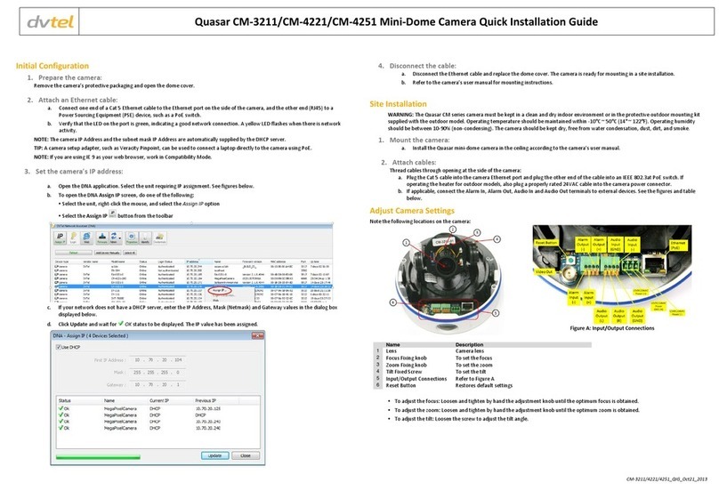
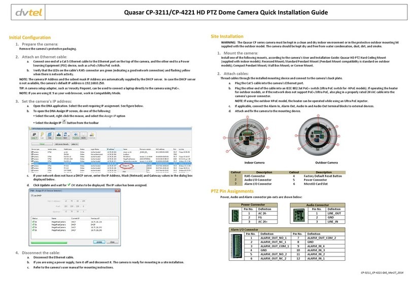
DVTEL CM-3211 Technical manual

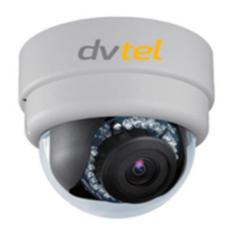
Quasar CM-3211 Series
Quasar CM-4221 Series
Mini-Dome Camera
User and Installation Guide
Rev B Nov. 2013

Document Information
i
Table of Contents
1Document Information....................................................................................................vi
2Overview .........................................................................................................................1
2.1 Features.......................................................................................................................... 2
2.2 Package Contents ...........................................................................................................3
2.3 Typical CM-3211/4221 Series Camera ...........................................................................4
3Introduction to the CM-3211/4221 Series IP Mini-Dome Camera.......................................5
3.1 CM-3211/4221 Indoor Camera Dimensions...................................................................5
3.2 CM-3211/4221-01 Outdoor Camera Dimensions .......................................................... 6
3.3 CM-3211/4221-10/10-I/11/11-I Motorized Camera Dimensions ..................................6
3.4 Camera Connections.......................................................................................................7
4System Requirements ......................................................................................................9
5Installation ....................................................................................................................11
5.1 Indoor Installation ........................................................................................................11
5.2 Outdoor Installation .....................................................................................................11
5.3 Power and Ethernet Cable Connection ........................................................................12
5.4 Initial Camera Configuration ........................................................................................ 12
5.5 Removing the Base Plate ..............................................................................................13
5.6 Mounting Instructions ..................................................................................................14
5.6.1 CM-3211/4221-10-I and CM-3211/4221-11-I Mounting Tips.................................. 14
5.6.2 Mounting the CM-3211/4221-00/10/10-I Indoor Camera ...................................... 15
5.6.3 Mounting the CM-3211/4221-01/11/11-I Outdoor Camera ................................... 17
6Using the DNA Utility to Search and Access the Camera ..................................................20
6.1 Introduction..................................................................................................................20
6.2 Quick Start ....................................................................................................................20
6.3 Main Screen.................................................................................................................. 21
6.4 Navigation Bar .............................................................................................................. 21
6.5 Context Menu............................................................................................................... 22
6.6 Configuring Communication Settings on the Quasar Camera......................................22
6.7 Adjusting and Framing-Up the Camera View ...............................................................26
7Configuration and Operation..........................................................................................29
7.1 Browser-Based Viewer Introduction ............................................................................29
7.2 Home Page....................................................................................................................31
7.2.1 CM-3211/4221-00/01 Varifocal Camera Home Page .............................................. 31
7.2.2 CM-3211/4221-10/10-I/11/11-I Motorized Camera Home Page ............................ 32
7.3 System-Related Settings...............................................................................................34
7.3.1 System ...................................................................................................................... 35

Quasar CM-3211/CM-4221 Series User and Installation Guide
ii
7.3.2 Security..................................................................................................................... 36
7.3.3 Network.................................................................................................................... 45
7.3.4 DDNS ........................................................................................................................ 51
7.3.5 Mail........................................................................................................................... 52
7.3.6 FTP............................................................................................................................ 53
7.3.7 HTTP ......................................................................................................................... 54
7.3.8 Application ............................................................................................................... 55
7.3.9 Motion Detection..................................................................................................... 59
7.3.10 Network Failure Detection....................................................................................... 63
7.3.11 Tampering ................................................................................................................ 65
7.3.12 Storage Management............................................................................................... 67
7.3.13 Recording ................................................................................................................. 69
7.3.14 Schedule ................................................................................................................... 70
7.3.15 File Location ............................................................................................................. 71
7.3.16 View Information ..................................................................................................... 72
7.3.17 Factory Default......................................................................................................... 75
7.3.18 Software Version...................................................................................................... 76
7.3.19 Software Upgrade .................................................................................................... 76
7.3.20 Maintenance ............................................................................................................ 78
7.4 Video and Audio Streaming Settings ............................................................................79
7.4.1 Video Format............................................................................................................ 79
7.4.2 Video Compression .................................................................................................. 90
7.4.3 Video OCX Protocol.................................................................................................. 91
7.4.4 Video Frame Rate..................................................................................................... 92
7.4.5 Video Mask............................................................................................................... 93
7.4.6 Audio ........................................................................................................................ 94
7.5 Camera-Related Settings ..............................................................................................95
7.5.1 Exposure................................................................................................................... 96
7.5.2 White Balance .......................................................................................................... 99
7.5.3 Picture Adjustment ................................................................................................ 100
7.5.4 Backlight................................................................................................................. 101
7.5.5 Digital Zoom ........................................................................................................... 101
7.5.6 IR Function ............................................................................................................. 102
7.5.7 WDR Function ........................................................................................................ 103
7.5.8 Noise Reduction ..................................................................................................... 104
7.5.9 TV System............................................................................................................... 105

Document Information
iii
7.6 Logout.........................................................................................................................106
8Appendices..................................................................................................................107
A.1. Technical Specifications..............................................................................................108
A.2. Device Search Software..............................................................................................111
A.2.1 Initial Camera Configuration .................................................................................. 111
A.2.2 Searching and Accessing the Camera with Device Search ..................................... 112
A.2.3 Configuring Communication Settings of a Quasar Camera.................................... 112
A.3. Internet Security Settings ...........................................................................................116
A.4. Install UPnP Components ...........................................................................................118
A.5. Deleting the Existing DCViewer ..................................................................................120
A.6. Deleting Temporary Internet Files..............................................................................121
A.7. Connecting Leads to a Spring Clamp Terminal Block .................................................122
A.8. Mounting Accessories ................................................................................................123
Contacting DVTEL...............................................................................................................126

Quasar CM-3211/CM-4221 Series User and Installation Guide
iv
List of Figures
Figure 1: Package Contents.......................................................................................................................3
Figure 2: Typical CM-3211/4221-xx Camera with Motorized Lens............................................................4
Figure 3: CM-3211/4221-00 Varifocal Indoor Camera Dimensions...........................................................5
Figure 4: CM-3211/4221-01 Varifocal Outdoor Camera Dimensions........................................................6
Figure 5: CM-3211/4221-10 Motorized Indoor Camera Dimensions.........................................................6
Figure 6: CM-3211/4221 Camera Input/Output Connections....................................................................7
Figure 7: Discovered IP Devices..............................................................................................................12
Figure 8: Network Setup Dialog Box........................................................................................................13
Figure 9: Inner Cover Removal................................................................................................................13
Figure 10: Releasing the Module.............................................................................................................14
Figure 11: Removing the Camera Module from the Base Plate..............................................................14
Figure 12: Base Plate Used as a Template to Mark Drilling Locations ...................................................15
Figure 13: Threading Wiring through the Base Plate...............................................................................16
Figure 14: Input/Output Connections and Reset Button..........................................................................17
Figure 15: Base Plate Used as a Template to Mark Drilling Locations ...................................................17
Figure 16: Top and Side Cable Entry Openings to Dome .......................................................................18
Figure 17: Replacing Camera Module onto Base Plate...........................................................................19
Figure 18: Reset Button and Input/Output Connections..........................................................................19
Figure 19: DNA Main Screen...................................................................................................................21
Figure 20: Context Menu..........................................................................................................................22
Figure 21: Windows Firewall Screen .......................................................................................................23
Figure 22: Discovered IP Devices............................................................................................................23
Figure 23: DNA Assign IP –Use DHCP Dialog Box................................................................................23
Figure 24: DNA Assign IP –Static IP Dialog Box....................................................................................24
Figure 25: Installing the ActiveX Control..................................................................................................25
Figure 26: Security Window.....................................................................................................................25
Figure 27: CM-3211/4221 Camera –Pan, Rotate and Tilt Angles..........................................................26
Figure 28: Quasar Browser-Based User Interface...................................................................................29
Figure 29: Home Page Function Buttons –for Varifocal Cameras..........................................................31
Figure 30: Home Page Function Buttons –for Cameras with Motorized Lens........................................32
Figure 31: Home Page –Step Range Drop-Down Menu ........................................................................33
Figure 32: System Screen........................................................................................................................34
Figure 33: System Configuration –Security ............................................................................................36
Figure 34: Security Screen.......................................................................................................................37
Figure 35: Editing Password and Privileges ............................................................................................38
Figure 36: Modifying Account Authority ...................................................................................................38
Figure 37: HTTPS Screen........................................................................................................................39
Figure 38: HTTPS Screen –Create Self-Signed Certificate....................................................................39
Figure 39: HTTPS Screen –Install Signed Certificate.............................................................................40
Figure 40: HTTPS Screen –Upload Signed Certificate...........................................................................40
Figure 41: Example of Self-Signed Certificate.........................................................................................41
Figure 42: Self-Signed Certificate –Details.............................................................................................41
Figure 43: IP Filter Screen.......................................................................................................................42
Figure 44: IEEE 802.1X/EAP-TLS Screen...............................................................................................44
Figure 45: Network Screen ......................................................................................................................45
Figure 46: QoS Screen ............................................................................................................................47
Figure 47: SNMP Settings Screen...........................................................................................................48
Figure 48: UPnP Screen..........................................................................................................................50
Figure 49: Direct Access to Camera with UPnP Enabled........................................................................50
Figure 50: DDNS Screen .........................................................................................................................51
Figure 51: Mail Screen –SMTP...............................................................................................................52
Figure 52: FTP Screen.............................................................................................................................53
Figure 53: HTTP Screen..........................................................................................................................54
Figure 54: Application Screen..................................................................................................................55
Figure 55: Application –Record Stream to SD Card...............................................................................56
Figure 56: Application –Upload Image by FTP.......................................................................................57
Figure 57: Application –Upload Image by E-Mail....................................................................................57
Figure 58: Application –Send HTTP Notification ....................................................................................58
Figure 59: Motion Detection Screen ........................................................................................................59
Document Information
v
Figure 60: Motion Detection Screen –with Schedule Drop-Down Menu ................................................60
Figure 61: Network Failure Detection Screen..........................................................................................63
Figure 62: Tampering Alarm Screen........................................................................................................65
Figure 63: Storage Management Screen.................................................................................................67
Figure 64: Video File Recording List........................................................................................................68
Figure 65: Selected File Window .............................................................................................................68
Figure 66: Recording Screen...................................................................................................................69
Figure 67: Schedule Screen.....................................................................................................................70
Figure 68: File Location Screen...............................................................................................................71
Figure 69: System Log Screen ................................................................................................................72
Figure 70: User Information Screen.........................................................................................................73
Figure 71: User Information –Privileges Screen.....................................................................................73
Figure 72: Parameter List Screen............................................................................................................74
Figure 73: Factory Default Screen...........................................................................................................75
Figure 74: Partial Restore Screen............................................................................................................75
Figure 75: Software Version Screen........................................................................................................76
Figure 76: Upgrade Screen......................................................................................................................76
Figure 77: Software Upgrade –In Process..............................................................................................77
Figure 78: Maintenance Screen...............................................................................................................78
Figure 79: File Download Screen.............................................................................................................78
Figure 80: Video Format Screen..............................................................................................................79
Figure 81: Video Rotate Type Screen......................................................................................................88
Figure 82: View-1 (Source)......................................................................................................................89
Figure 83: View-2 Image Rotated Vertically (Reversed)..........................................................................89
Figure 84: Video Compression Screen....................................................................................................90
Figure 85: Video OCX Protocol Screen ...................................................................................................91
Figure 86: Video Frame Rate Screen ......................................................................................................92
Figure 87: Mask Screen...........................................................................................................................93
Figure 88: Audio Screen ..........................................................................................................................94
Figure 89: Camera Settings Screen.........................................................................................................95
Figure 90: Camera Settings Screen –Exposure .....................................................................................96
Figure 91: Camera Settings Screen –White Balance .............................................................................99
Figure 92: Camera Settings Screen –Picture Adjustment....................................................................100
Figure 93: Camera Settings Screen –Backlight....................................................................................101
Figure 94: Camera Settings Screen –Digital Zoom ..............................................................................101
Figure 95: Camera Settings Screen –IR Function................................................................................103
Figure 96: Camera Settings Screen –WDR Function...........................................................................103
Figure 97: Camera Settings Screen –Noise Reduction........................................................................104
Figure 98: Camera Settings Screen –TV System.................................................................................105
Figure 99: Login Message......................................................................................................................106
Figure 100: Login Window .....................................................................................................................106
Figure 101: Device Search Application..................................................................................................111
Figure 102: Windows Security Alert.......................................................................................................113
Figure 103: Device Search Application –Select Browse.......................................................................114
Figure 104: Device Search Application –Select Install ActiveX Control ...............................................114
Figure 105: Security Warning Window...................................................................................................114
Figure 106: Command Bar Toolbar –Select Internet Options...............................................................116
Figure 107: Internet Options Screen......................................................................................................116
Figure 108: Command Bar Toolbar –Internet Options..........................................................................117
Figure 109: Schedule Screen ................................................................................................................117
Figure 110: Spring Clamp Terminal Block.............................................................................................122
Figure 111: Connecting a Wire to a Terminal Block ..............................................................................122

Quasar CM-3211/CM-4221 Series User and Installation Guide
vi
1Document Information
Document Scope and Purpose
The purpose of this document is to provide instructions and installation procedures for physically
connecting the Quasar camera. After completing the physical installation, additional setup and
configurations may be required before video analysis and detection can commence.
Note:
This document is intended for use by technical users who have a basic
understanding of CCTV camera/video equipment and LAN/WAN network
connections.
Warning:
Installation must follow safety, standards, and electrical codes as well as the laws
that apply where the units are being installed.
Proprietary Rights and Non-Disclosure
This manual is delivered subject to the following restrictions and conditions:
This document contains proprietary information belonging to DVTEL, Inc. This information
is supplied solely for the purpose of assisting explicitly the licensee of the DVTEL units.
No part of this document contents may be used for any other purpose, disclosed to any
third party or reproduced by any means, electronic or mechanical, without the express
prior written permission of DVTEL, Inc.
Trademarks and Copyrights
This manual and its contents herein are owned by DVTEL, Inc. All rights reserved.
DVTEL, the DVTEL logo, Quasar CM-3211/4221 are trademarks of DVTEL, Inc.
Products and trademarks mentioned herein are for identification purposes only and may be
registered trademarks of their respective companies.
DVTEL, Inc. makes no representations whatsoever about any other products or trademarks
mentioned in the manual.
2013 © DVTEL, Inc. All rights reserved

Document Information
vii
Disclaimer
Users of DVTEL products accept full responsibility for ensuring the suitability and considering the
role of the product detection capabilities and their limitation as they apply to their unique site
requirements.
DVTEL, Inc. and its agents make no guarantees or warranties to the suitability for the users’ intended
use. DVTEL, Inc. accepts no responsibility for improper use or incomplete security and safety
measures.
Failure in part or in whole of the installer, owner, or user in any way to follow the prescribed
procedures or to heed WARNINGS and CAUTIONS shall absolve DVTEL, Inc. and its agents from any
resulting liability.
Specifications and information in this guide are subject to change without notice.
Document Conventions
WARNING and CAUTION notes are distributed throughout this document, whenever applicable, to
alert you of potentially hazardous situations. These may be hazards associated with a task or a
procedure you are carrying out or are about to carry out.
The following document conventions are used throughout this manual:
A Warning is a precautionary message that indicates a procedure or condition where
there are potential hazards of personal injury or death.
A Caution is a precautionary message that indicates a procedure or condition where
there are potential hazards of permanent damage to the equipment and or loss of data.
A Note is useful information to prevent problems, help with successful installation, or to
provide additional understanding of the products and installation.
A Tip is information and best practices that are useful or provide some benefit for
installation and use of DVTEL products.
General Cautions and Warnings
This section contains information that indicates a procedure or condition where there are potential
hazards. These may be hazards associated with a task or procedure a user is carrying out or about to
carry out. WARNINGS and CAUTIONS are distributed throughout this document, whenever
applicable, to alert the user of potentially hazardous situations.
SAVE ALL SAFETY AND OPERATING INSTRUCTIONS FOR FUTURE USE.
Although the unit is designed and manufactured in compliance with all applicable safety standards,
certain hazards are present during the installation of this equipment.

Quasar CM-3211/CM-4221 Series User and Installation Guide
viii
To help ensure safety and to help reduce risk of injury or damage, observe the following:
Warning:
1. The camera covers is an essential part of the product. Do not open or remove it.
2. Never operate the camera without the cover in place. Operating the camera
without the cover poses a risk of fire and shock hazards.
3. Do not disassemble the camera or remove screws. There are no user serviceable
parts inside the unit.
4. Only qualified trained personnel should service and repair this equipment.
5. Observe local codes and laws and ensure that installation and operation are in
accordance with fire, security and safety standards.
Electrical Safety Notice and Warnings
Warning:
1. Read the installation instructions before you connect the unit to a power source.
2. Electrical safety should always be observed. All electrical connections must be
performed by a certified electrician.
3. Use the supplied power supply and protect against static electricity, ground
faults and power surges.
4. The unit uses a three-wire power cord to make sure that the product is properly
grounded when in use. This is a safety feature. If the intended power outlet does
not support three prongs, one of which is a ground, contact an electrician to
install the appropriate outlet. NEVER remove or otherwise attempt to bypass the
ground pin of the power cord. Do not operate the unit in the absence of a
suitably installed ground conductor.
5. If you use an extension cord with this system, make sure that the total ampere
rating on the products plugged into the extension cord does not exceed the
extension cord ampere rating.
6. To avoid possible shock hazards or damaging the unit, assure that the positive
and negative of the power leads are properly connected to the terminal block
connector before plugging it into the unit or turning on the power source.
7. In the following situations, the electric power should be turned off immediately
and appropriate repairs, replacements or remedies should be taken if:
The power line is damaged, frayed or shows heavy wear.
The unit has been physically crushed or deformed.
The unit has been exposed to water.
The unit has been exposed to, or shows signs of damage from, fire, intense heat,
heavy smoke, fumes, or vapors.
Electrical connections of the unit become abnormally hot or generate smoke.
The unit has been dropped, damaged or shows signs of loose internal parts.
The unit does not operate properly.

Document Information
ix
Caution:
To avoid damage from overheating or unit failure, assure that there is sufficient
temperature regulation to support the unit’s requirements (cooling/heating). Operating
temperature should be kept in the range 0° to 50°C (32° to 122°F), with no more than
90% non-condensing humidity.
Minimizing EMI and RFI
When wires run for a significant distance in an electromagnetic field, electromagnetic interference
(EMI) can occur. Strong EMI (e.g. lightning or radio transmitters) can destroy the units and can pose
an electrical hazard by conducting power through lines and into the system. Poor quality or worn
wiring can result in radio frequency interference (RFI). To minimize the effects of EMI and RFI,
consult your reseller.
Site Preparation
There are several requirements that should be properly addressed prior to installation at the site.
The following specifications are requirements for proper installation and operation of the unit:
Ambient Environment Conditions: Avoid positioning the unit near heaters or
heating system outputs. Avoid exposure to direct sunlight. Use proper
maintenance to ensure that the unit is free from dust, dirt, smoke, particles,
chemicals, smoke, water or water condensation, and exposure to EMI.
Accessibility: The location used should allow easy access to unit connections and
cables.
Safety: Cables and electrical cords should be routed in a manner that prevents
safety hazards, such as from tripping, wire fraying, overheating, etc. Ensure that
nothing rests on the unit’s cables or power cords.
Ample Air Circulation: Leave enough space around the unit to allow free air
circulation.
Cabling Considerations: Units should be placed in locations that are optimal for
the type of video cabling used between the unit and the cameras and external
devices. Using a cable longer than the manufacturer’s specifications for optimal
video signal may result in degradation of color and video parameters.
Physical Security:The unit provides threat detection for physical security systems.
In order to ensure that the unit cannot be disabled or tampered with, the system
should be installed with security measures regarding physical access by trusted
and un-trusted parties.
Network Security:The unit transmits over IP to security personnel for video
surveillance. Proper network security measures should be in place to assure
networks remain operating and free from malicious interference. The unit is
intended for installation on the backbone of a trusted network.
Electrostatic Safeguards:The unit as well as other equipment connected to it
(relay outputs, alarm inputs, racks, carpeting, etc.) shall be properly grounded to
prevent electrostatic discharge.
The physical installation of the unit is the first phase of making the unit operational in a security
plan. The goal is to physically place the unit, connect it to other devices in the system, and to
establish network connectivity.


Overview
1
2Overview
The Quasar CM-3211 Series IP Mini-Dome Camera provides real-time, 720p, H.264 multi-streaming
with the highest quality image. Its compact, sophisticated mechanical design and snap-in camera
chassis facilitate easy installation. The CM-3211 series includes the following models (collectively
referred to as CM-3211-xx):
CM-3211-00 Indoor Camera with varifocal lens
CM-3211-01 Outdoor Camera with varifocal lens
CM-3211-10 Indoor Camera with motorized lens
CM-3211-10-I Indoor Camera with motorized lens and infrared IR illuminator
CM-3211-11 Outdoor Camera with motorized lens
CM-3211-11-I Outdoor Camera with motorized lens and infrared IR illuminator
The Quasar CM-4221 Series IP Mini-Dome Camera provides real-time, 1080p, H.264 multi-streaming
with the highest quality image. Its compact, sophisticated mechanical design and snap-in camera
chassis facilitate easy installation. The CM-4221 series includes the following models (collectively
referred to as CM-4221-xx):
CM-4221-00 Indoor Camera with varifocal lens
CM-4221-01 Outdoor Camera with varifocal lens
CM-4221-10 Indoor Camera with motorized lens
CM-4221-10-I Indoor Camera with motorized lens and infrared IR illuminator
CM-4221-11 Outdoor Camera with motorized lens
CM-4221-11-I Outdoor Camera with motorized lens and infrared IR illuminator
Caution:
If you are using DVTEL Latitude, we recommend that you configure the camera’s settings
via the AdminCenter. This is because the camera’s web-based interface might be
overwritten by Latitude settings. Refer to the Latitude online help for information
regarding configuring camera settings.

Quasar CM-3211/CM-4221 Series User and Installation Guide
2
2.1 Features
Following are key features of the CM-3211/4221 series cameras:
H.264 and MJPEG compression
HTTP streaming MJPEG
Progressive scan CMOS sensor
Edge motion detection
Motion detection with region of
interest masking
Historical motion-detection
levels detected/recorded at
frame levels.
Detection event driven alarms
Alarm input driven events
Relay output actions on alarm
Built-in web application/web server
FTP upload (up to two locations)
Upload alarm images to FTP
Dual HTTP notification server support
(up to two servers)
Send images on alarm to e-mail
E-Mail SMTP alarm
notification (up to two e-
mails)
MicroSD/SDHC recording support
Record snapshots to SD card on
alarm
Sequential snapshot
numbering
SNMP v1/v2/v3 and SNMP traps
Security IP restricted access
allow/deny list
UPnP support
Electronic day/night (ICR)
Analog video output
BNC analog output
Privacy masks
WDR and ATW
3DNR image noise reduction
ONVIF support
RTSP support
Supports PoE /12VDC/24VAC
Multiple users
Group permissions
Per-user permissions
Tampering detection and notification
Two encoder streams available
Low-lux mode and backlight
compensation
Vandal-proof IP66 enclosure
(CM-3211/4221-01/11/11-I)
Motorized lens
(CM-3211/4221-10/11/11-I)
Infrared LED illuminator
(CM-3211/4221-10-I/11-I)
Note:
MJPEG is not supported by Latitude.

Overview
3
2.2 Package Contents
Before proceeding, please check that the box contains the items listed here. If any item is missing or
has defects, do not install or operate the product and contact your dealer for assistance.
Mini-Dome camera
(Torx wrench)
Rubber washers (×6)
Self-tapping screws (×4)
(See Note below)
Plastic screw anchors
(×4)
CD
(Bundled software and
documentation)
Quick-start guide
Figure 1: Package Contents
Note:
The self-tapping screws are mainly for softer substrate/material installation such as
wood. For other installation materials such as cement ceilings, it is necessary to pre-
drill and use plastic anchors before fastening the supplied self-tapping screws into
the wall.

Quasar CM-3211/CM-4221 Series User and Installation Guide
4
2.3 Typical CM-3211/4221 Series Camera
The figure below shows a typical CM-3211/4221 series camera.
Figure 2: Typical CM-3211/4221-xx Camera with Motorized Lens
Table 1: CM-3211/4221 Camera Control Descriptions
Item
Designation
Description
1
Lens
Camera lens
2
Focus fixing knob
To set the focus, loosen and tighten by hand the adjustment
knob until the optimum focus is obtained
3
Zoom fixing knob
To set the zoom, loosen and tighten by hand the adjustment
knob until the optimum zoom is obtained
4
Tilt fixed screw
To set the tilt, loosen the screw, adjust the tilt angle and
tighten screw
5
Input/output
connections
Refer to Figure 6
6
Reset button
Restores the default setting

Introduction to the CM-3211/4221 Series IP Mini-Dome Camera
5
3Introduction to the CM-3211/4221 Series IP Mini-Dome Camera
This chapter provides the camera dimensions for reference before installation. Each connector
located inside the camera’s housing is also identified. See Figure 6 and Table 2.
Related Links
CM-3211/4221-00 Indoor Camera Dimensions
CM-3211/4221-01 Outdoor Camera Dimensions
CM-3211/4221-10/10-I/11/11-I Motorized Camera Dimensions
Camera Connections
Technical Specifications
3.1 CM-3211/4221 Indoor Camera Dimensions
The CM-3211/4221-00 IP Indoor Varifocal Mini-Dome Camera’s dimensions are shown below.
Figure 3: CM-3211/4221-00 Varifocal Indoor Camera Dimensions

Quasar CM-3211/CM-4221 Series User and Installation Guide
6
3.2 CM-3211/4221-01 Outdoor Camera Dimensions
The CM-3211/4221-01 Varifocal IP Outdoor Mini-Dome Camera dimensions are shown below.
Figure 4: CM-3211/4221-01 Varifocal Outdoor Camera Dimensions
3.3 CM-3211/4221-10/10-I/11/11-I Motorized Camera Dimensions
The CM-3211/4221-10, CM-3211/4221-10-I, CM-3211/4221-11, and CM-3211/4221-11-I Indoor and
Outdoor Motorized IP Mini-Dome Camera dimensions are shown below.
Figure 5: CM-3211/4221-10 Motorized Indoor Camera Dimensions
Related Link
Technical Specifications

Introduction to the CM-3211/4221 Series IP Mini-Dome Camera
7
3.4 Camera Connections
Figure 6 shows the various connectors and Reset button contained within the housing of the
CM-3211/4221-xx camera. The connectors, pin numbers and signal definitions related to each pin
are listed in Table 2.
Figure 6: CM-3211/4221 Camera Input/Output Connections
Table 2: CM-3211/4221 Camera Connector Designations
Connector
Pin No.
Definition
Remarks
BNC
N/A
Analog Video Output
Alarm I/O
1
2
3
4
GND (Input-)
Input+
Output-
Output+
Alarm connection
Audio I/O
1
2
3
4
Output (L)
Output (R)
GND
Input
Two-way audio
transmission
Power
12VDC
1
2
3
Power
Reserved
GND
Power connection
24VAC
1
2
3
Power-1
Earth GND
Power-2
RJ45
N/A
10/100 Mbps Ethernet/PoE
Table 3: CM-3211/4221 Camera Reset
Switch
Pin No.
Definition
Remarks
Reset Button
N/A
Restores to factory default


System Requirements
9
4System Requirements
To access the camera via a web browser, ensure that your PC has the proper network connection
and meets system requirements as described below.
Table 4: System Requirements
Item
Minimum System Requirement
Personal Computer
Intel® Pentium® M, 2.16 GHz or Intel® CoreTM2 Duo2.0 GHz
2GB RAM or more
Operating System
Windows, Windows XP, Windows 7
Web Browser
Microsoft Internet Explorer 7, 8, or 9
Network Card
10Base-T (10 Mbps) or 100Base-TX (100 Mbps) operation
Viewer
ActiveX control plug-in for Microsoft IE
Other manuals for CM-3211
1
This manual suits for next models
11
Table of contents
Other DVTEL Security Camera manuals

DVTEL
DVTEL Quasar CM-3211-00 Manual

DVTEL
DVTEL CB-5222 User manual

DVTEL
DVTEL Quasar CP-3211 User manual

DVTEL
DVTEL CM-3211 User manual

DVTEL
DVTEL 9600 Series User manual

DVTEL
DVTEL Quasar User manual

DVTEL
DVTEL ioimage CP-2202-361P/N Manual

DVTEL
DVTEL Quasar CP-3211-180 Manual

DVTEL
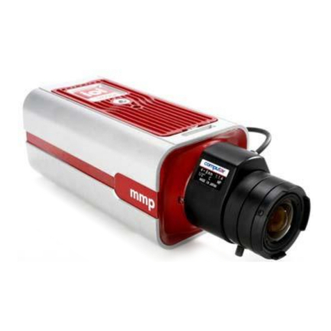
DVTEL ioimage mmp100dn User manual

DVTEL
DVTEL Pro Line 9460A User manual