- 2 -
1
2
3
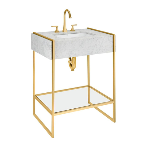
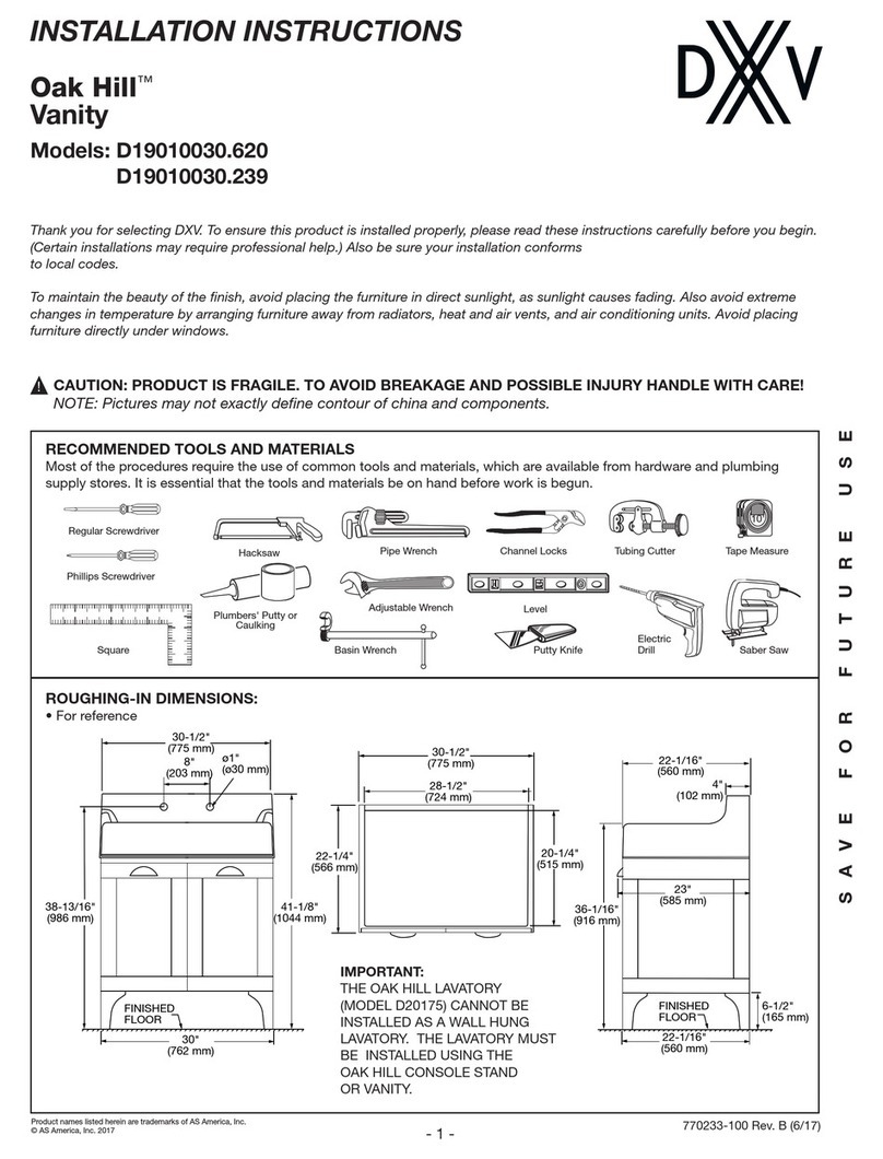
CONSOLE STAND INSTALLATION
EXPLODED VIEW
IMPORTANT: Suitable reinforcement is required for anchoring
the lavatory to the wall.
Determine horizontal centerline location “*” of lavatory
mounting holes. (see Figure 1).
Rough in supply lines and waste per rough in dimensions.
Insert the Locator Pins (6K) into the round holes in the ends of Glass Shelf Frame (1)
so that the points face out. The shoulders must be ush with the end of the Glass Shelf
Frame. (see Figure 2)
Install the M5x5 mm Set-Screws (6H) into the Glass Shelf Frame.
Tighten the Set Screws so that the Locator Pins are secure.
Attach the other ends of the Glass Shelf Frame to the Legs (2), by sliding the ends with the
notched round holes (Figure 3) over the factory-installed Square Connectors (6C).
NOTE: The Set-Screw holes are located on the underside of Glass Shelf Frame.
Install the Set-Screws and, with the ends of the Glass Shelf Frame ush with the side of
the Legs, tighten the Set-Screws securely.
Insert a Square Connector into the recess in the Leg, with the notched end outward. Slide
a Lock Washer (6E) onto a M5x50mm Mushroom Head Screw (6J) and insert it into the
hole in the center of the Square Connector (6C), threading it into the Towel Bar (5).
NOTE: Do not tighten completely at this time.
770187-100 Rev. E (6/17)
ITEM DESCRIPTION PART NUMBER
1(1) Glass Shelf Frame 770209-201.YYY0A
2 (1) Leg 770210-201.YYY0A
3(1) Glass Shelf 770211-201.YYY0A
4 (1) Support Tube - Horizontal 770212-201.YYY0A
5(1) Towel Bar 770213-201.YYY0A
6HARDWARE/COMPONENT KIT
6A - (1) Allen Wrench - M5
6B - (4) Circular Connectors
6C - (2) Square Connectors
6D - (4) Wall Escutcheons
6E - (2) Lock Washers - 304 Stainless Steel
6F - (4) Wood Screws - M5x50mm -
Countersunk Head
6G - (4) Wall Anchors
6H - (8) Set Screws - M5x5mm
6J - (2) Screws -M5x50mm - Mushroom Head
6K - (4) Locator Pins
6L - (4) Set Screws - M3x3.5mm
(Factory Installed)
6M - (1) Allen Wrench - M3
6N - (1) Bumper Replacement Kit (not shown)
770214-201.YYY0A
1
2
5
3
4
6E
6D
6C
6F
6M
6A
6G
6B
6H
6J
6K
6L
Finished
Floor
C/L of 2 x 6
Reinforcement
FIGURE 1
FIGURE 2
FIGURE 3
4
