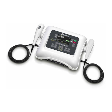
Dynatronics Dynatron 825 User manual

DYNATRON® 25 SERIES™ | OPERATOR’S MANUAL I

DYNATRON® 25 SERIES™ | OPERATOR’S MANUAL II
IMPORTANT: Before treating a patient with any Dynatron® 25 Series™ Device, see the “Contraindications, Warnings,
and Precautions” in this manual. Read the operating instructions for each modality carefully.
COMPLIANCE: e contents of this “Instructions For Use” manual are exactly the same in both the printed and electronic
forms.
INDICATIONS FOR USE
ELECTROTHERAPY: Electrical muscle stimulation therapy (Russian, Biphasic, High Volt) for:
1. relaxation of muscle spasm;
2. prevention or retardation of disuse atrophy;
3. increasing local blood circulation;
4. muscle re-education;
5. immediate post-surgical stimulation of calf muscles to prevent venous thrombosis
6. maintaining or increasing range of motion.
Transcutaneous electrical nerve stimulation and Interferential Current erapy (Interferential, Premodulated, and High
Volt) for: Symptomatic relief of chronic intractable and/or management of post-traumatic or post-surgical pain.
ULTRASOUND THERAPY: Ultrasound therapy is intended to generate deep heat within body tissues for the
treatment of selected medical conditions such as relief of pain, muscle spasms, and joint contractures, but not for
the treatment of malignancies.
CAUTION
Federal law restricts these devices for sale by or on the order of a physician, chiropractor, physical therapist, or
dentist licensed by the law of the state in which said person practices to use or order the use of the devices.
Risk of burns and re - Do not use near conductive materials such as metal bed parts, inner spring mattresses
and the like.
DANGER - Explosion Hazard: Do not use in the presence of ammable anesthetics.
08/08/2016- Rev. 0
Inventory 5D00280
All Rights Reserved
ISO 13485
NEMKO CERTIFIED
DQS CERTIFIED
Dynatron® 25 Series™ Operation Manual
©Copyright 2016
Dynatronics Corporation
7030 Park Centre Drive Salt Lake City, UT 84121
(801) 568-7000 / (800) 874-6251 / www.dynatronics.com
Emergo Europe
Molenstraat 15
e Hague, 2513 BH
e Netherlands
0470
EC REP

TABLE OF CONTENTS
DYNATRON® 25 SERIES™ | OPERATOR’S MANUAL III
Table of Contents
Section I: Introduction
Introduction to the Dynatron® 25 Series™ ............................................................................................. 1
Summary of Features by Device...............................................................................................................................................1
Simplied Setup .........................................................................................................................................................................2
Language Selection ....................................................................................................................................................................2
Operator’s Prole .......................................................................................................................................................................2
Before You Treat a Patient.........................................................................................................................................................3
Installation and Features........................................................................................................................ 4
Unpacking...................................................................................................................................................................................4
Standard Components...............................................................................................................................................................4
Dynatron® 25 Series Physical Features................................................................................................... 7
Channels and Jacks ..................................................................................................................................................................12
Current Limit............................................................................................................................................................................14
Error Messages .........................................................................................................................................................................15
Ultrasound Error Messages ....................................................................................................................................................16
Lead Wires ................................................................................................................................................................................16
Testing Leads ............................................................................................................................................................................17
Carbon Electrodes ...................................................................................................................................................................18
Self-Adhesive Electrodes.........................................................................................................................................................19
Electrotherapy Information and Usage Cautions................................................................................ 21

TABLE OF CONTENTS
DYNATRON® 25 SERIES™ | OPERATOR’S MANUAL IV
Section II: Operation and Treatment Instructions
Interferential / Premodulated Instructions ......................................................................................... 25
Detailed Interferential / Premodulated Setup......................................................................................................................25
Interferential and Premodulated Modality Information..................................................................... 29
Interferential (Quadpolar) erapy.......................................................................................................................................29
Premodulated (Bipolar) erapy ...........................................................................................................................................30
Target .........................................................................................................................................................................................30
Why Is Target Better? ..............................................................................................................................................................30
Target Sweep .............................................................................................................................................................................31
Interferential Electrode Placement........................................................................................................................................31
Interferential / Premodulated Default Settings....................................................................................................................31
Interferential Default Settings ................................................................................................................................................31
Premodulated Default Settings...............................................................................................................................................31
Biphasic / Russian Instructions ........................................................................................................... 32
Biphasic / Russian Quick Setup..............................................................................................................................................33
Detailed Biphasic / Russian Setup..........................................................................................................................................34
Biphasic / Russian Modality Information............................................................................................ 37
Russian Stimulation .................................................................................................................................................................37
Biphasic Stimulation................................................................................................................................................................37
Biphasic / Russian Parameters and Defaults.........................................................................................................................37
High Volt Instructions ......................................................................................................................... 40
High Volt Electrode Setup ......................................................................................................................................................40
Detailed High Volt Setup ........................................................................................................................................................41
High Volt Quick Setup ............................................................................................................................................................41
High Volt Modality Information ......................................................................................................... 45
High Volt Waveform................................................................................................................................................................45
High Volt Settings ....................................................................................................................................................................45
High Volt Default Settings ......................................................................................................................................................46
High Volt Waveform Specications.......................................................................................................................................46
Ultrasound Instructions....................................................................................................................... 47
Soundhead Warming...............................................................................................................................................................48
Coupling....................................................................................................................................................................................48
Head Temperature Hot Display .............................................................................................................................................49
Display Watts or W/cm2..........................................................................................................................................................49
Detailed Ultrasound Setup .....................................................................................................................................................50
Ultrasound Quick Setup..........................................................................................................................................................50

TABLE OF CONTENTS
DYNATRON® 25 SERIES™ | OPERATOR’S MANUAL V
Ultrasound Modality Information....................................................................................................... 53
Selecting the Appropriate Soundhead...................................................................................................................................53
Penetration of Ultrasound Waves ..........................................................................................................................................54
Types of Delivery......................................................................................................................................................................55
Treatment Time........................................................................................................................................................................55
Treatment Intensity..................................................................................................................................................................55
Frequency of Treatment ..........................................................................................................................................................56
Usage Cautions – Combination Treatments.........................................................................................................................56
Potential for Burns or Periosteal Pain ...................................................................................................................................56
Ultrasound Problem Solving ............................................................................................................... 58
Whirlpool Treatments .............................................................................................................................................................58
Soundhead Temperature Too Cold........................................................................................................................................58
No Soundhead..........................................................................................................................................................................59
Miscellaneous ...........................................................................................................................................................................59
Replacing the Soundhead .......................................................................................................................................................59
Ultrasound Specications .......................................................................................................................................................60
Ultrasound Regulation and Technical Information ............................................................................................................60
Ultrasound Beam Proles.................................................................................................................... 61
Combination erapy Instructions ..................................................................................................... 63
Comboplus™..............................................................................................................................................................................63
Stim rough the Soundhead ................................................................................................................................................64
Combination erapy Setup...................................................................................................................................................65
Modify A Treatment ................................................................................................................................................................66
Combination Default Settings................................................................................................................................................66
Simultaneous Treatments .................................................................................................................... 67
Set Up A Second Treatment....................................................................................................................................................67
Modify Simultaneous Treatments..........................................................................................................................................67
Section III: Contraindications, Warnings, and Precautions
Contraindications, Warnings, & Precautions ..................................................................................... 69
Contraindications ....................................................................................................................................................................69
Warnings ...................................................................................................................................................................................69
Precautions................................................................................................................................................................................70
Treatment Setup Warnings .....................................................................................................................................................71
Adverse Eects .........................................................................................................................................................................71
Contraindications, Warnings, & Precautions for Ultrasound Treatment.......................................... 73
Contraindications ....................................................................................................................................................................73
Precautions................................................................................................................................................................................74
Warnings ...................................................................................................................................................................................75
TABLE OF CONTENTS
DYNATRON® 25 SERIES™ | OPERATOR’S MANUAL VI
Section IV: Technical Information
Technical Information.......................................................................................................................... 76
Setting Defaults ........................................................................................................................................................................76
Save New Defaults....................................................................................................................................................................76
Restore Factory Defaults .........................................................................................................................................................77
Battery Operation ................................................................................................................................ 78
Battery Life................................................................................................................................................................................79
General Specications.......................................................................................................................... 80
Dynatron 25 Series Specications..........................................................................................................................................80
Environmental Conditions .....................................................................................................................................................80
Safety Features of the Dynatron 25 Series.............................................................................................................................81
Care and Cleaning Instructions .............................................................................................................................................81
Suggested Maintenance Schedule ..........................................................................................................................................82
Routine Ultrasound Calibration Inspections for 25 Series.................................................................................................83
Soware Updates......................................................................................................................................................................84
Returning a Unit for Repair....................................................................................................................................................85
Denition of Symbols and Labeling......................................................................................................................................86
Equipment Classication ........................................................................................................................................................87
Disposal of Equipment and Accessories ...............................................................................................................................87
Basic Troubleshooting Techniques ...................................................................................................... 88
Lead Testing..............................................................................................................................................................................88
Testing Carbon Pads................................................................................................................................................................89
CAN/CSA Waveform Requirements.................................................................................................... 90
Electromagnetic Emissions and Immunity ......................................................................................... 96
Medical Device Reporting Requirements.......................................................................................... 100
Denition of serious injury ..................................................................................................................................................100
Reporting any Incident of Patient Discomfort...................................................................................................................101
Dynatron® 25 Series Plus Limited Warranty ..................................................................................... 102
25 Series Warranty Registration...........................................................................................................................................103

INTRODUCTION TO THE DYNATRON® 25 SERIES™
DYNATRON® 25 SERIES™ | OPERATOR’S MANUAL 1
Introduction
to the Dynatron®25 Series™
e powerful and versitle 25 Series oers 3 and 5 channel devices. All channels allow fully-independent treatment setups
oering Interferential, Premodulated, High Volt, Biphasic, Russian, Microcurent, and xed frequency IFC/Premod. In
addition, the 925 and 825 include Dynatronics’ Ultrasound Comboplus feature with the power to deliver up to 5 channels
of Stim and Ultrasound - all at the same time. All of the Dynatron 25 Series models oer 1, 2, and 3 MHz frequencies for
the greatest exibility in depth of treatment. Choose 1 MHz for deep treatments, 2 MHz for moderate depth, or 3 MHz for
supercial depth.
Summary of Features by Device
Feature 925 825 625 525
Electrotherapy
IFC X X X X
Premod X X X X
Biphasic X X X X
Russian X X X X
High Volt X X X X
Combo Electrotherapy/Ultrasound X X
Ultrasound X X
Available Channels
Electrotherapy Channels 5 3 5 3

INTRODUCTION TO THE DYNATRON® 25 SERIES™
DYNATRON® 25 SERIES™ | OPERATOR’S MANUAL 2
Feature 925 825 625 525
High Volt Channel 1 1 1 1
Ultrasound Channel 1 1
Combo Channel 1 1
e 25 Series devices include the standard advantages of Dynatronics engineering, such as customizable treatments, electrode
conductance meters, and the popular Target feature. In addition all units oer the option of battery operation, making the devices
truly portable. e manufacturer’s warranty for these devices is two years (see full warranty details at the back of this manual).
is manual provides operator information and instructions for the four 25 Serises models: the 525, 625, 825, and 925.
e section that discusses Ultrasound and Combo treatments applies only to the Dynatron 825 and 925 models. All other
sections of this manual apply to all Dynatron 25 Series devices.
Simplied Setup
e design of the 25 Series top panel means treatment setup has never been easier. A few simple key presses are all you need
to fully set up a treatment. e User Interface intuitively groups and displays all the options for a modality setup on the large
LCD screen to ensure that treatment parameters can easily be selected and adjusted.
Each modality oers default settings which are automatically preset when the modality is selected—saving time in the treatment
setup. You can change these defaults to match your own most common treatment setups reducing setup time to a matter of seconds.
Language Selection
e default language on the 25 Series Family of devices is English; however, both French and Spanish are also available. To
change the default language: 1) Begin at the START UP SCREEN. 2) Press the FUNCTION KEY. 3) Use the toggle key under
the LANGUAGE WINDOW to select the desired language. 4) Press STOP to return to the START UP SCREEN.
Operator’s Prole
All operators shall be properly trained and certied medical practitioners or those working under the direction of a licensed
medical practitioner, capable of reading and comprehending instructions for use as described in this manual. Operators will
have reasonable mobility and dexterity to attach electrodes, apply ultrasound or light therapy accessories and monitor patient
WARNING
Power-on the device before attaching electrodes to the patient.

INTRODUCTION TO THE DYNATRON® 25 SERIES™
DYNATRON® 25 SERIES™ | OPERATOR’S MANUAL 3
response to attended or unattended treatments. e operator should be able to hear an audible signal indicating completion
of treatments. ere should be no other limitations for operating this device.
Before You Treat a Patient
Before administering a treatment to a patient with the 25 Series devices, you should familiarize yourself with all the operating
instructions for the modality used, as well as the contraindications, warnings, and precautions for that modality. You should
also read the general information about each of the modalities provided in this manual. In addition to this information, consult
other published sources for additional application and safety instructions regarding use of each type of therapy.
CAUTION
Device should be at room temperatrue prior to treatment.

INSTALLATION AND FEATURES
DYNATRON® 25 SERIES™ | OPERATOR’S MANUAL 4
Installation and Features
Unpacking
When you receive the unit, immediately unpack it and all accessories and check for possible damage, obvious or concealed.
In case of damage, immediately notify the freight carrier and take any steps necessary to le a claim for the damage sustained.
Do not destroy or discard the shipping carton. e carton should be reused if the device must be shipped for any reason
including calibration. e carton is specially designed to protect the unit from shipping damage. Improper packaging of the
unit during transport can result in damage and invalidate the warranty.
Complete the warranty registration form located at the back of this manual and return it to Dynatronics within 30 days
of purchase. is is essential to insure you are not billed for services that are covered by the warranty policy. Warranty
registration should include serial numbers for both the device and soundheads.
Connect the AC power cord, which is provided as a hospital grade, UL listed plug, to a properly grounded 110/120V 60 Hz
AC outlet (the device will automatically switch to 220/240V 50 Hz when connected to a power source with that voltage).
e power cord must also be rmly plugged into the device itself. When the cord is properly connected, it cannot be easily
pulled out. Do not place the cord or the device in a place where the cord could be tripped over or accidentally pulled out of
its socket during a treatment.
Read the operating instructions in this manual before proceeding with a treatment.
Standard Components
REF e following accessories are included with the 25 Series units:
Qty Part No. Description: One of the following devices:
1 D925T Dynatron 925 5-Channel Combination Stim and Ultrasound
1 D825T Dynatron 825 3-Channel Combination Stim and Ultrasound
1 D625T Dynatron 625 5-Channel Stim
1 D525T Dynatron 525 3-Channel Stim

INSTALLATION AND FEATURES
DYNATRON® 25 SERIES™ | OPERATOR’S MANUAL 5
Qty Part No. Description: One of the following devices:
1 7B0241 Power Cord (black)
1 5D00280 Operator’s Manual
1 7B0268 Protocol Reference Manual for Electrotherapy & Ultrasound (J. Stephen Guey, P.T., Ed., D.)
1 7B0284 Ultra Polys™self-adhesive electrodes 2” x 4” (5.08cm x 10.16cm) w/ pin connector (pkg. of 4)
1 DW248 2.5” x 48” (6.35cm x 121.92cm) straps (pkg. of 2)
1 7B0191 5” x 8” (12.7cm x 20.32cm) dispersive electrode for High Volt (gray)
1 7B0201 Sponge Fabric for use with 5”x 8” (12.7cm x 20.32cm) dispersive electrodes
Dynatron 825 and 525
1 7B03020 96” (243.84cm) shrouded lead (1 red)
1 7B03030 96” (243.84cm) shrouded lead (1 black)
Dynatron 625 and 925
2 7B03020 96” (243.84cm) shrouded lead (2 red)
2 7B03030 96” (243.84cm) shrouded lead (2 black)
Dynatron 825 and 925 Ultrasound
1 7B0217 DynaGel Ultrasound Gel 100 ml sample
1 7B03040 Combo lead wires
Soundheads
e Dynatron 125 devices may be purchased with one or more applicator soundheads in the following sizes:
Part No. Size Frequencies
WSH02 2 cm2Operates at 1, 2, and 3 MHz
WSH05 5 cm2Operates at 1, 2, and 3 MHz
WSH10 10 cm2Operates at 1, 2, and 3 MHz
Optional Accessories
e following optional and replacement accessories may be purchased from Dynatronics or from your Dynatronics dealer:
Part No. Description
D71BAG So Side Carrying Case
D71CART 25 Series Cart
7B0208 2" (5.8cm) diameter carbon electrodes (red)

INSTALLATION AND FEATURES
DYNATRON® 25 SERIES™ | OPERATOR’S MANUAL 6
Part No. Description
7B0209 2" (5.8cm) diameter carbon electrodes (gray)
7B0063 3" (7.62cm) diameter carbon electrodes (red)
7B0065 3" (7.62cm) diameter carbon electrodes (gray)
7B0059 3" x 5" (7.62cm x 12.7cm) carbon electrodes (red)
7B0061 3" x 5" (7.62cm x 12.7cm) carbon electrodes (gray)
7B0067 1.5" x 2.0" (3.81cm x 5.8cm) carbon electrodes (red)
7B0069 1.5" x 2.0" (3.81cm x 5.8cm) carbon electrodes (gray)
7B0260 2" x 4" (5.8cm x 10.16cm) Ultra Polys™adhesive electrodes (w/snap or pin)
7B0261 2" x 2" (5.8cm x 5.8cm) Ultra Polys™square adhesive electrodes (w/snap or pin)
7B0077 Bifurcated extension lead wire for High Volt use
7B0082 Pin-to-Banana adapter (black)
7B0079 Banana-to-Pin Adapter (black)
7B0001 Snap adapter
5LTRGEL Ultrasound Coupling Gel (5 liter container)

DYNATRON® 25 SERIES PHYSICAL FEATURES
DYNATRON® 25 SERIES™ | OPERATOR’S MANUAL 7
Dynatron®25 Series
Physical Features
Before operating the Dynatron 25 Series devices, acquaint yourself with the control panel by reviewing the illustrations and
descriptions on the following pages. e numbered features in the diagrams correspond to the numbered descriptions.
Before administering treatment to a patient, read the sections later in this manual that provide specic instructions for
performing treatments, discussions of each modality, denitions of the available options, along with contraindications,
warnings, and precautions for all modalities.
Note: e User Interface on the 25 Series devices is engineered with “CapSense Touch Technology” requiring that the user
make direct contact with the keys on the faceplate with bare ngers or the use of a glove with a conductive ngertip.

DYNATRON® 25 SERIES PHYSICAL FEATURES
DYNATRON® 25 SERIES™ | OPERATOR’S MANUAL 8
1. START: Press the green START key on the right side of the Treatment Display Screen to start the treatment timer
and treatment proceeds as set up.
e START key can also be used to save new treatment DEFAULT settings. Aer setting up a treatment, press
and hold the START key for two seconds. At the end of two seconds, a beep will sound indicating the treatment
parameters have been saved. e next time the modality is selected, these parameters will be selected automatically.
2. STOP: Pressing the red STOP key during a treatment IMMEDIATELY stops the output and sets the treatment time
to zero for all modalities. To stop only the focus treatment, reduce the focus treatment’s time to zero.
3. PAUSE: e PAUSE key is designed to pause Ultrasound treatments.
4. FUNCTION: is key is used to access unique features for High Volt, Ultrasound, Combo treatments and for
entering soundhead parameters. e FUNCTION key is also used in conjunction with the STOP key to stop only
a treatment in focus. In addition, the FUNCTION KEY provides access to settings for STIM, LANGUAGE, LEAD
TESTS AND SYSTEM INFORMATION. Specic instructions for using this key are provided later in the manual as
they apply to each function or modality.
5. TREATMENT DISPLAY SCREEN: Located in the upper center of the USER INTERFACE, the TREATMENT
DISPLAY SCREEN allows the clinician to view all of the parameters of the focus treatment such as time, intensity,
frequency, duty cycle, contraction rest, ramp time, polarity, or any other setting applicable to a treatment at a glance.
In addition, the screen lists all active modalities not in focus along with their active channels and remaining treatment
times in small font under the heading RUNNING TREATMENTS. If an error occurs during treatment, an error message
will appear on the Treatment Display Screen identifying the treatment modality that triggered the error message.
6. ARROW KEYS: e UP/DOWN arrow keys are used to increase/decrease the treatment time or other parameters
that appear on the TREATMENT DISPLAY SCREEN directly next to the arrow keys being used.
7. MODALITY KEYS: e 25 Series devices have the following treatment modality options: IFC, Premod, Ultrasound,
Combo, Biphasic, Russian, and High Volt. MODALITY KEYS appear at the bottom of the USER INTERFACE.
Pressing any of the available MODALITY KEYS will bring the selected modality into focus and the default parameters
for that treatment modality will be displayed. Treatment modality parameters may be customized once the treatment
is in focus.
8. TREATMENT WINDOWS: Across the bottom of the TREATMENT DISPLAY SCREEN are ve smaller treatment
windows providing treatment options and parameters that are unique to each modality. e quick access and
visibility of these TREATMENT WINDOWS allow for quick, easy, and accurate setup. On the following pages are
illustrations of each modality’s TREATMENT WINDOWS and their associated default settings.
Note: High Volt, Sound, and Combo treatments all have a secondary set of TREATMENT WINDOWS and treatment
options that are accessed when the treatment is in focus and the FUNCTION key is pressed. e arrow between the
two boxes indicates the secondary treatment window.

DYNATRON® 25 SERIES PHYSICAL FEATURES
DYNATRON® 25 SERIES™ | OPERATOR’S MANUAL 9
IFC (Interferential) Premod
Biphasic Russian
SOUND (Ultrasound) SOUND (Function Key View)
COMBO (Combination) COMBO (Function Key View)

DYNATRON® 25 SERIES PHYSICAL FEATURES
DYNATRON® 25 SERIES™ | OPERATOR’S MANUAL 10
9. TREATMENT WINDOW TOGGLE KEYS: TOGGLE KEYS are located below the ve TREATMENT WINDOWS.
Pressing the toggle key directly below a window allows the one to choose an output channel, and select treatment
parameters for a treatment in focus. A treatment is in focus when the name of the treatment appears in the center of
the TREATMENT DISPLAY SCREEN.
10. CHANNELS WINDOW / CHANGING THE FOCUS TREATMENT
e lights in the CHANNELS window indicate which output channels/jacks are currently in use. e channel(s)/jack
illuminated in GREEN indicates the focus treatment and the time, intensity, and other treatment parameters for that
active treatment appear on the Treatment Display Screen. A solid YELLOW light indicates a channel/treatment is in
use and delivering current, but the intensity, and treatment parameters are not displayed at this time (only one
channel’s parameters may be displayed at a time). A treatment’s parameters may only be modied when the treatment
is brought into focus. To bring a treatment into focus, press the CHANNELS TOGGLE key below the CHANNELS
window to select a channel to be brought into focus. If a treatment that is active but not the focus treatment times-out,
the text in the CHANNELS window will change from YELLOW to WHITE.
11. TARGET PAD: ere’s no easier, more ecient way to focus treatment precisely where it’s needed! Simply glide
your nger across the TARGET touch pad to move the center of interference to the site of your patient’s pain. e
patient’s input will help direct you. When you li your nger from the Target pad, the selected point is locked until
you change it again.
HIVOLT (High Volt) HIVOLT (Function Key View)

DYNATRON® 25 SERIES PHYSICAL FEATURES
DYNATRON® 25 SERIES™ | OPERATOR’S MANUAL 11
12. CONDUCTANCE/TEMPERATURE BAR
Conductance.
e 25 Series devices continuously measure conductance during electrical Stim treatments for Interferential, and
Premod to ensure that the treatment outcome is optimal and to minimize the possibility of patient discomfort due
to poor conductance and/or changes in current density. As conductance is measured, 25 Series displays the results
in graph form on the CONDUCTANCE bar located on the right side of the TREATMENT DISPLAY SCREEN.
Optimum conductance is displayed as the conductance bar ows RED - YELLOW- GREEN. GREEN indicating
the best CONDUCTANCE. If the green bar only partially lls the graph area, the conductance is at a percentage
of optimum. Lower INTENSITY may cause the bar to partially ll, but does not mean that the treatment is not
eective. Below are some helpful denitions.
Conductance and Worn Electrodes.
Conductance is how readily electrical current is passed from the electrode to the skin surface during a treatment.
Conductance aects current density. A worn electrode that does not conduct the current evenly over its entire
surface will have “hot spots” where a greater amount of current ows through a smaller area which means the
current density is higher at that point than elsewhere on the electrode. “Hot Spots” can lead to patient discomfort.
Never risk patient comfort by using worn electrodes or lead wires.
Intensity.
e intensity level is a convenient incremental measurement. However, raising the intensity increases the current
delivered to the patient but does not improve conductance.
Current Density.
Current density is the amount of current that passes through a given area of the electrode. Current density varies
depending on the size of the electrode, the conductance, and intensity setting; and has an eect on patient comfort.
With proper setup and good accessories, current is dispersed evenly over the entire surface of the electrode. e
smaller the electrode, the greater the density of the current delivered through the area. To reduce current density and
improve patient comfort, use larger electrodes, or lower the intensity setting, or both.
If the number of green displayed segments begin to decrease on the graph during a treatment, it is important to
determine the cause of the poor conductance. Remember with poor conductance you may inadvertently increase
current density at a small point under the electrode and cause patient discomfort. Following are some considerations
to insure proper conductance.
• Check to be sure electrodes are not worn or that self-adhesive electrodes have not lost their adhesiveness. ese
are the most common causes of poor current delivery. Both self-adhesive and carbon electrodes eventually lose
their ability to conduct current eectively. See “Electrotherapy Usage Cautions” in this manual for recommended
intensity settings and usage limits.
• Check to ensure the entire surface of the poly adhesive electrode is adhering.
• Self-adhesive electrodes do not require sterilization, however, electrodes should be clean and hydrated (see
package instructions or “Self-Adhesive Electrodes” section of this manual).
• Check to be sure the snap adapters haven’t fallen o or that the lead wire has not become disconnected from the
electrodes or the device.
• Make sure carbon electrodes have a secure connection with the pin ends of the leads. Over time the carbon
electrodes may become too loose to use safely and the electrodes must be replaced.

DYNATRON® 25 SERIES PHYSICAL FEATURES
DYNATRON® 25 SERIES™ | OPERATOR’S MANUAL 12
• Check for corrosion on lead ends.
• Make sure carbon electrodes are adequately moistened and free from build-up to allow complete contact across
the surface of the electrode.
• Observe the electrode placement. Some areas of the patient’s body conduct current better than others. In areas
where resistance is high you may be unable to obtain optimum conductivity.
• Check the dryness of the patient’s skin. Dry skin does not conduct current well.
• Check to see if the electrodes do not adhere properly when a patient shis position during a treatment. Worn
electrodes could become loose and a signicant change in conductance could result.
Temperature.
e25Series devices continuouslymeasure temperatureduringUltrasound,andComboTreatment.TEMPERATURE
is indicated by the length of the Blue/Green indicator lights on the temperature bar. e longer the length of the
colored bar, the higher the temperature. It is not uncommon to have the temperature bar move into the medium
length ranges. If the temperature approaches the maximum level of 108° Fahrenheit (42.22° Celsius), the treatment
is automatically PAUSED, output power stopped, and treatment time stops counting down. Following a cooling
period, the treatment may be continued by pressing START.
Channels and Jacks
13. Front Panel Channels and High Volt Jack
Illustrated below are the dual-channel banana jacks for delivering Interferential, Premodulated, Russian, and Biphasic
treatments. ese channels are located on the front of the device. As you face the device, channels 1 and 2 are on the
le, channels 3 and 4 are on the right with the dedicated High Volt jack for delivering High Volt Pad treatments in
the middle. ree channel units (525 and 825) have channels 1, 2, and High Volt only.
Front Panel Channels and Jack

DYNATRON® 25 SERIES PHYSICAL FEATURES
DYNATRON® 25 SERIES™ | OPERATOR’S MANUAL 13
14. Le-Side Panel Jacks
SD Card Input. Located on the le-side of the 25 Series devices is the SD Card Input. e SD Input provides a way
for the 25 Series Devices to receive soware updates quickly and easily. Complete instructions for updating the
devices using an SD card are found in the “Technical” information section of the manual.
15. Right-Side Panel Jacks
Located on the right-side of the 25 Series are the Ultrasound, Combo Stim Probe Jacks. Non-ultrasound devices
(525 and 625) have no input jacks on the right-side panel.
Input (ElectroStim Combo Jack).
e special combo lead wire for combination treatments is plugged into this jack for a combination treatment setup
providing Stim output through the Ultrasound head. e Combination Treatment (Combo) Jack is a simple banana
jack connector and requires no special alignment.
Ultrasound Jack.
e Ultrasound Jack is a keyed jack with a “D” shaped conguration. Align the straight bottom of the jack and the
round top that matches the conguration found on the Ultrasound cord. Do not force or twist the connector or
damage to the pins may occur. When removing the connector, pull the connector’s outer sleeve directly away from
the chassis. When an Ultrasound probe is connected, the device console will update the probe calibration data. No
user inputs will be required to update calibration data.
Le-Side Panel Jacks
Right-Side Panel Jacks

DYNATRON® 25 SERIES PHYSICAL FEATURES
DYNATRON® 25 SERIES™ | OPERATOR’S MANUAL 14
Back Panel Jacks
a. POWER CORD ENTRY MODULE. is entry module is designed to accommodate a hospital-grade
power cord.
b. Power 1/0 (ON/OFF) Switch. Located on the back of the unit this switch is labeled “1” and “0.” Set the switch
to “1” for ON; set the switch to “0” for OFF.
c. Battery. is jack may be used to supply power to the device using an optional battery pack. More information
about the optional battery operation is provided later in this manual.
Current Limit
e Dynatron 25 Series devices continuously measure the actual current output during IFC and Premod treatments and
limit the output current to the level set for the device. As the intensity of a treatment is increased the current output is also
increased.
When the maximum output current limit is reached, the device will immediately stop increasing the intensity and
automatically reduce the intensity a few increments to prevent the possibility of patient discomfort. Simultaneously, the
device will beep and one of the following CURRENT LIMIT WARNINGS will appear in the lower right-hand corner of the
Treatment Display Screen. Following is a list of CURRENT LIMIT WARNINGS that may occur.
NOTE: Patient Remote Stop. Adding the Remote Stop requires a custom order. e Patient Remote Stop Jack is
located below the Light Probe holder. e remote stop is controlled by the patient during unattended therapy, allowing
the patient to stop the treatment at any time. When the button on the remote stop cable is pressed, output for all Stim
modalities and pad treatments is stopped. During Combo treatments, both Sound and Stim outputs are stopped.
Back Panel Jacks
a b c
Remember to treat at the patient’s comfort level. It is not important to reach a given intensity level. It is only
important to set the treatment at a level that is comfortable to the patient. See “Electrotherapy Usage Cautions” in
this manual for suggested intensity limits.
This manual suits for next models
3
Table of contents
Other Dynatronics Medical Equipment manuals

Dynatronics
Dynatronics Dynatron 850 Plus User manual

Dynatronics
Dynatronics Dynatron T3 User manual

Dynatronics
Dynatronics dynatron solaris 709 plus User manual

Dynatronics
Dynatronics Solaris Plus D715T User manual

Dynatronics
Dynatronics Hausmann 6175 Installation instructions

Dynatronics
Dynatronics DYNATRON SmarTRAC User manual