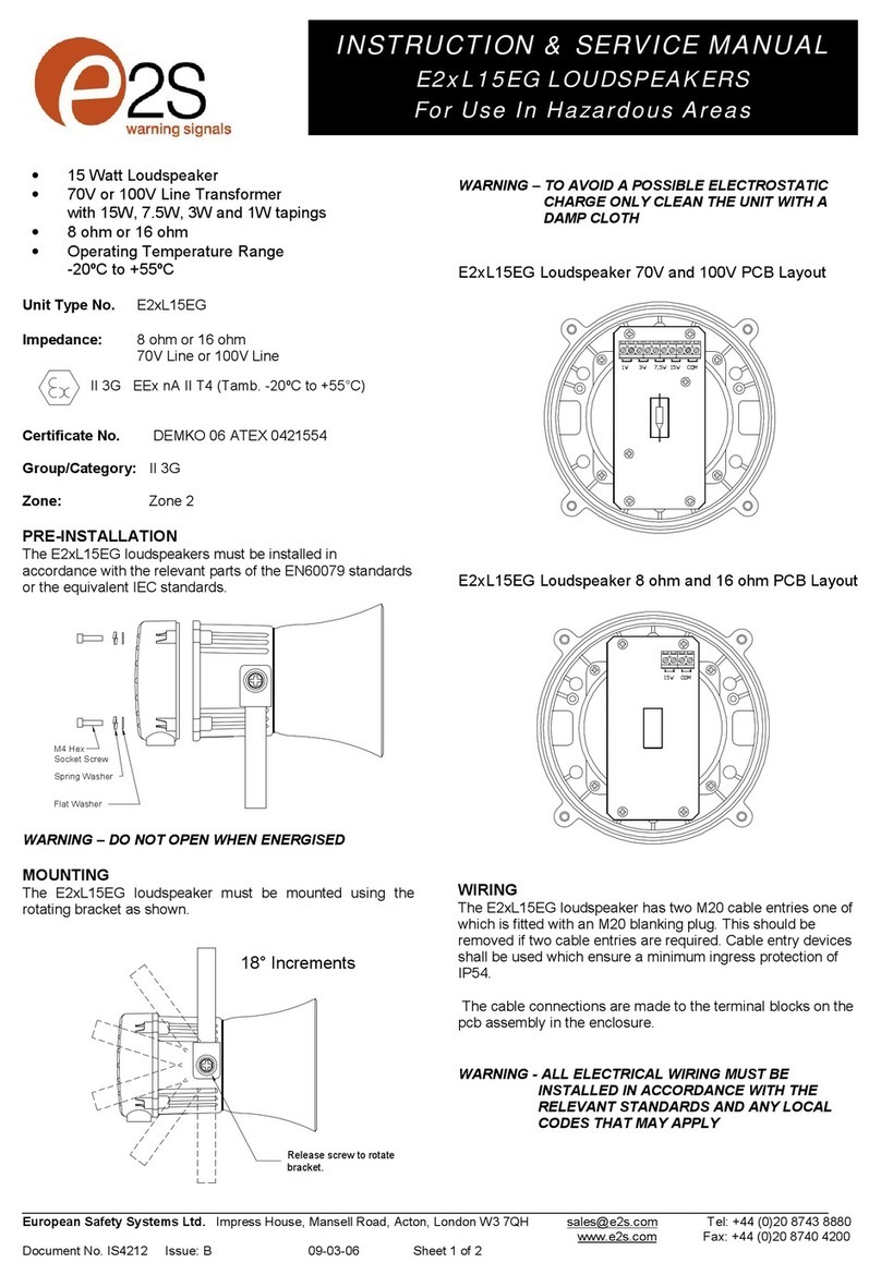
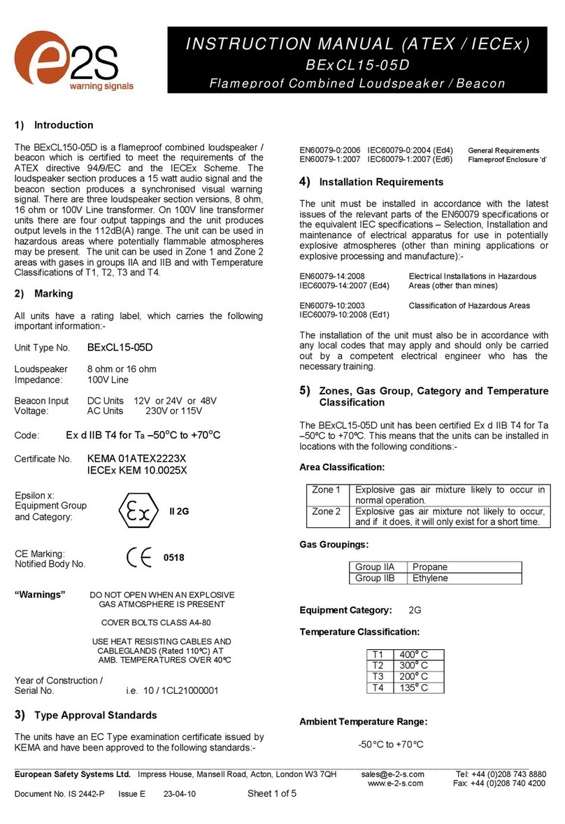
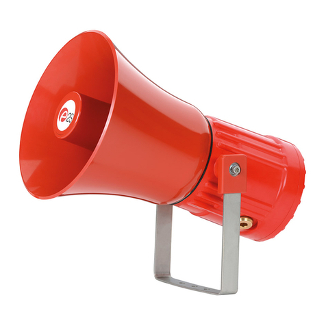
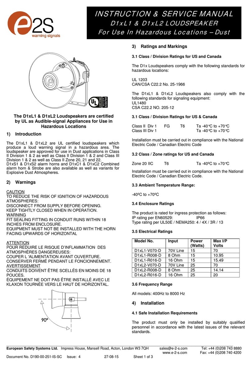
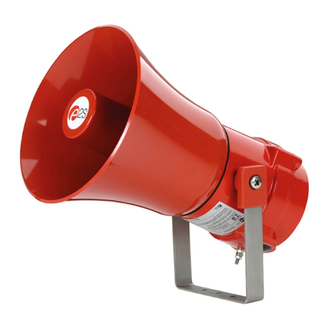
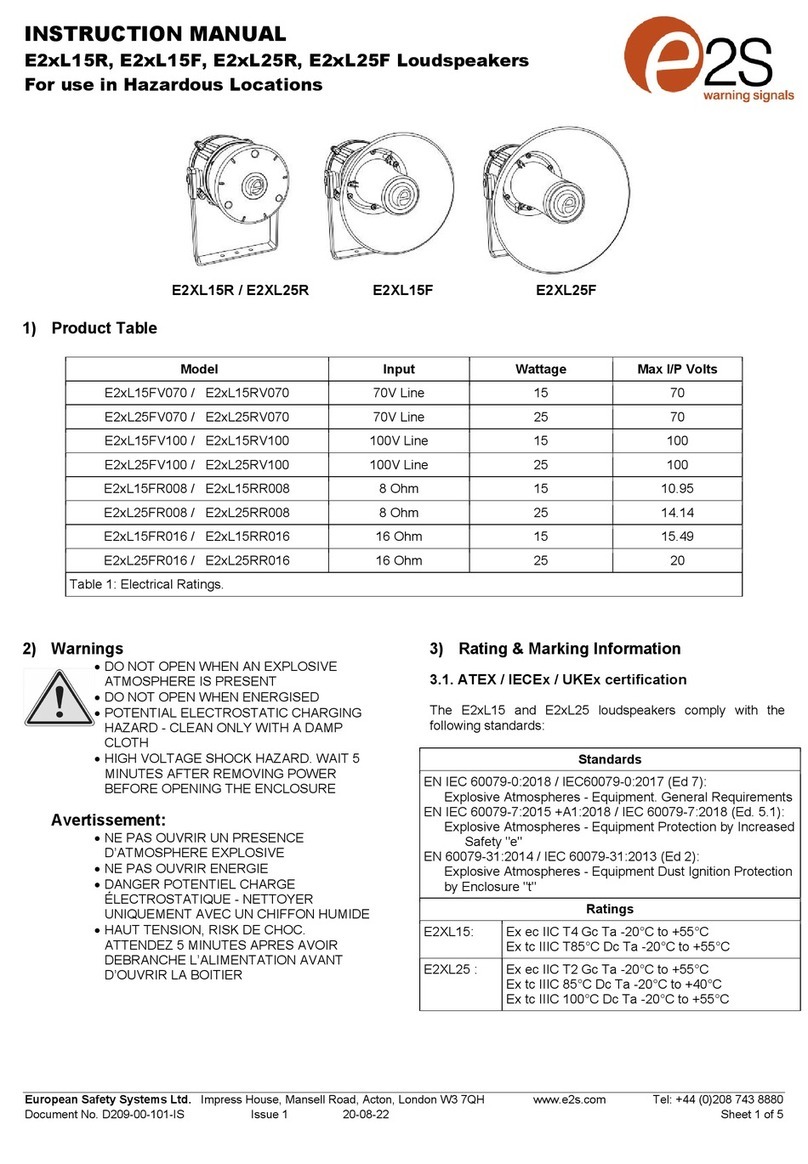
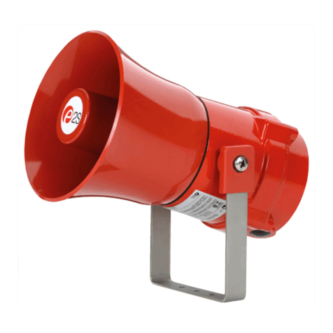
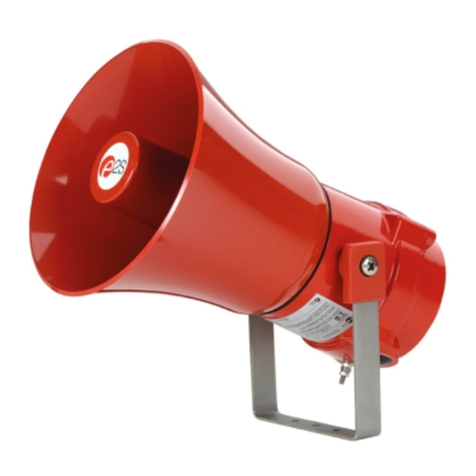
E2S BExDL15D User manual

__________________________________________________________________________________________________________________________________
EuropeanSafetySystemsLtd. Impress House, MansellRoad, Acton, LondonW37QHsales@e-2-s.com Tel: +44(0)208743 8880
www.e-2-s.com Fax: +44(0)208 7404200
DocumentNo. IS2453-PIssueE12-03-10Sheet 1of 4
INSTRUCTION MANUAL(ATEX/IECEx)
BExDL25DandBExDL15D
FlameproofLoudspeakers
ForuseinFlammableGasandDustAtmospheres
1)Introduction
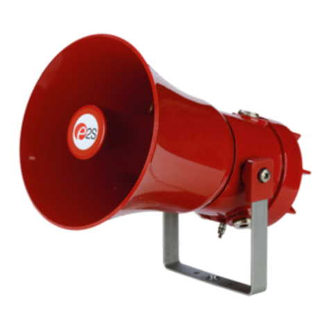
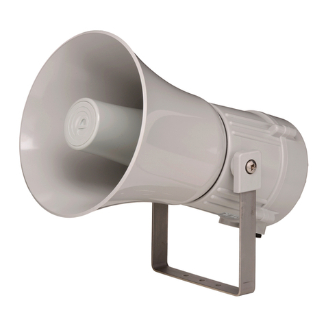
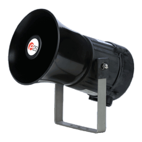
The BExDL25D and BExDL15D areflameproofloudspeakers
whicharecertifiedto the meet the requirementsof the ATEX
directive94/9/ECandIECExscheme.The loudspeakerscan
beused in hazardousareaswherepotentially flammablegas
and dustatmospheresmaybe present. Therearefour
versionsofeachloudspeaker, 8 ohmor16ohmand70Vor
100V Line transformer. On70Vand 100Vlinetransformer
unitsthere are four outputtappings foreachsizeof
loudspeaker. TheBExDL25Dunit produces output levels in the
117dB(A)rangeand theBExDL15Dunit producesoutput
levelsinthe 112dB(A) range.Bothloudspeakerscanbe used
in Zone 1 and Zone 2areaswith gasesin groups IIA,IIB and
IICand temperature Classifications ofT1,T2,T3andT4.For
ambient temperaturesover +55ºCthegasgroupsare limited to
IIAand IIB.They canalso beused inZone21andZone 22
areas for combustible dusts and have anIP rating of IP67 and
asurfacetemperaturerating ofT100ºCup to+55ºCand
T115ºC over +55ºC.
2)Marking
All unitshavearating label, whichcarriesthe following
important information:-
UnitTypeNo. BExDL25DorBExDL15D
Impedance:8ohmor16 ohm
70V Line or 100VLine
Codes:ExdIICT4forTa–50°Cto+55°C
ExdIIBT4forTa–50°Cto+70°C
ExtDA21 IP67T115°Cbased onmaxTaof +70°C
CertificateNo’s KEMA99ATEX6312
IECExKEM10.0003
“Warnings” DONOTOPENWHENANEXPLOSIVE
GASORDUSTATMOSPHEREISPRESENT
COVERBOLTSCLASS A4-80
USE HEATRESISTINGCABLES ANDCABLEGLANDS
(Rated 110ºC)ATAMB. TEMPERATURES OVER40ºC
Year of Construction/
Serial No. i.e. 10 / 1DL23000001
3) TypeApprovalStandards
The loudspeakershaveECTypeExamination andIECEx
certificates issuedbyKEMAandhave been approved tothe
followingstandards:-
EN60079-0:2006 IEC60079-0:2004(Ed4) GeneralRequirements
EN60079-1:2007 IEC60079-1:2007 (Ed6) Flameproof Enclosure‘d’
EN61241-0:2006 IEC61241-0:2004(Ed1)DustGeneral
Requirements
EN61241-1:2004 IEC60079-1:2004(Ed1)DustEnclosurestD
4) InstallationRequirements
The loudspeakersmustbe installedinaccordancewiththe
latestissuesofthe relevantpartsof theBSEN 60079
specificationsorthe equivalentIEC specifications –Selection,
Installationandmaintenance of electrical apparatus foruse in
potentially explosiveatmospheres (otherthanmining
applications or explosiveprocessingandmanufacture):-
EN60079-14:2008 ElectricalInstallationsinHazardous
IEC60079-14:2007(Ed4) Areas(otherthan mines)
EN60079-10:2003 Classificationof HazardousAreas
IEC60079-10:2008(Ed1)
The installationof theunitsmustalsobe in accordance with
anylocal codesthat may apply and should onlybe carried out
by a competent electrical engineerwho has had thenecessary
training.
5) Zones,GasGroup,Category,IPRating and
TemperatureClassification
The BExDL25D andBExDL15D loudspeakers have beenhave
been certifiedExd IICT4 for Ta–50°Cto+55ºC and Exd IIB
T4 for Ta –50°Cto +70ºC for gasandExtD A21IP67T115ºC
basedon max. Ta of+70ºCfor dust. This means thatthe units
canbe installed in locationswith thefollowingconditions:-
AreaClassification Gas:
Zone 1
Explosivegasair mixturelikely tooccurin
normal operation.
Zone 2
Explosivegasair mixturenot likely to occur,
andifitdoes, it willonly exist for a short time.
GasGroupings:
GroupIIA
Propane
GroupIIB
Ethylene
GroupIIC
(Up to+55ºC only)
Hydrogen andAcetylene
0518
II
2G
/D
CE Marking:
NotifiedBody No.

__________________________________________________________________________________________________________________________________
EuropeanSafetySystemsLtd. Impress House, MansellRoad, Acton, LondonW37QHsales@e-2-s.com Tel: +44(0)208743 8880
www.e-2-s.com Fax: +44(0)208 7404200
DocumentNo. IS2453-PIssueE12-03-10 Sheet2of 4
TemperatureClassification:
T1
400
o
C
T2
300
o
C
T3
200
o
C
T4
135
o
C
AreaClassification Dust:
Zone 21
Explosive dust airmixturelik
ely to occur in
normal operation.
Zone 22
Explosive dust air mixturenotlikelytooccur,
andif it does, it will onlyexist fora short time.
IPRating IP67 T100ºC Ta < +55ºC
T115ºC Ta < +70ºC
EquipmentCategory: 2G/D
Ambient Temperature Range:
-50°C to+55°CGasGroupsIIA, IIB andIIC
-50°C to+70°CGasGroup IIAandIIB
6) LoudspeakerLocationandMounting
The locationoftheloudspeakersshouldbemade withdue
regardtotheareaoverwhich the unitmustbeaudible. The
loudspeakersshould onlybefixedto servicesthatcancarry
the weight ofthe unit.
The loudspeakersshouldbesecurely bolted to asuitable
surface usingthe 7mmdiameter boltholesinthe stainlesssteel
Ushaped mounting bracket(seefigure 1). Theanglecanthen
be adjustedin thedirection that the sound is primarily required
tocover. Thiscan be achievedbyloosening thetwo large
bracketscrews in the side of the unit, which allowadjustment
in steps of 18°. Oncompletion of the installation the two large
bracketadjustment screwsontheside of the unit mustbe fully
tightenedto ensurethat theunit cannotmovein service.
7) AccesstotheFlameproofEnclosure
Inorder toconnectthe audiosupply cables to the loudspeaker
it is necessary to removetheflameproofcovertogain access
totheflameproofchamber. To achievethisremovethefour M6
hexagon sockethead screws (see figure2) andwithdrawthe
flameproof cover takingextremecarenotto damagethe
flameproof joints in theprocess.
Notethefour M6screwsareClass A4-80stainless steel
and onlyscrewsof thiscategorycanbeused on these
loudspeakers. It istherefore importantthatthese screwsand
their springwashersarekept in a safe place duringinstallation.
Oncompletionof thecable wiring installationtheflameproof
jointsshould be inspectedto ensurethat theyarecleanand
thatthey havenotbeen damagedduringinstallation.Also
checkthat theearthbonding wirebetween thetwocasting
sections issecureandthe‘O’ringseal isinplace.When
replacingtheflameproof cover casting ensurethat itis square
withthe flameproof chamber castingbefore inserting. Carefully
push thecoverin placeallowing timefor theair to be expelled.
Only afterthecover isfullyinplace, should the fourM6
Stainless SteelA4-80 coverbolts and theirspringwashers be
insertedand tighteneddown. If the coverjamswhile it isbeing
inserted, carefully remove it andtry again.Never use thecover
boltsto force the cover intoposition.
8) PowerAmplifierSelection
Itisimportant thattheloudspeakersareconnectedto power
amplifiersthat haveoutputsthat arecompatibletothetype of
loudspeakerbeingused.Loudspeakerswith a70Vor100V
line matching transformerfitted mustbeconnected to apower
amplifier with a70Vor100Vline output.Lowimpedance 8
ohm or16 ohmloudspeakers must beconnected to amplifiers
withasuitablelowimpedance output. Whenselectingthe
cable size considerationmustbegivento thecurrentthateach
unitdraws,thenumberofloudspeakerson thelineandthe
length ofthe cablerun.
The followingtableshows therangeofloudspeakers:-
UnitType InputWattageMax.
I/PVolts
BExDL25D 100VLine 25W 100V
BExDL25D 70Vline25W 70V
BExDL25D 8ohm 25W 14.14V
BExDL25D 16 ohm25W 20V
BExDL15D 100VLine 15W 100V
BExDL15D 70VLine 15W 70V
BExDL15D 8ohm 15W 10.95V
BExDL15D 16 ohm15W 15.49V
The above tablealso showsthe maximum ACsignalvoltages
at whichthe loudspeakers canbe operated.
Figure 1
Flameproof
Chamber
Flameproof
Cover
S/SMounting
Bracket
Figure2
4off M6CoverScrews
ExternalEarth
Terminal
PlasticAcousticHorn
(Anti-staticPlastic)

__________________________________________________________________________________________________________________________________
EuropeanSafetySystemsLtd. Impress House, MansellRoad, Acton, LondonW37QHsales@e-2-s.com Tel: +44(0)208743 8880
www.e-2-s.com Fax: +44(0)208 7404200
DocumentNo. IS2453-PIssueE12-03-10 Sheet3of 4
The currentlevelstakenbytheeachloudspeakerwill depend
onwhich output tapping hasbeenselected (see section13 of
this instructionmanual).BExDL25D70Vand100VLine units
haveoutputlevelsof 25W,12.5W,6Wand2W;BExDL15D
70V and 100VLine unitshave output levels of15W,7.5W,3W
and 1W.
9) CableSelection
Whenselecting the cable size consideration mustbegivento
the current that eachunit draws,thenumberofloudspeakers
onthelineandthelengthof thecableruns.
SAFETY WARNING: Iftheloudspeakers are usedathigh
ambienttemperatures,i.e.over+40ºC, thenthecable entry
temperature mayexceed +70ºCand thereforesuitable heat
resistingcables mustbeused,witharatedservice
temperature of at least 110ºC.
10) Earthing
All loudspeakers mustbe connectedtoagood quality earth.
The unitsareprovidedwithinternal and externalearthing
terminalswhichare bothlocatedonthe flameproofcover
sectionoftheunit (seefigures 2and3).
Whenusingtheinternal earth terminalensure thatthe
stainlesssteelM4flat washer isbetweentheincoming earth
wireand the enclosure.
Whenusing theexternal earthterminalacablecrimp lug must
be used. Thecablelugshouldbe located between thetwoM5
stainlesssteelflat washers.The M5 stainlesssteelspring
washermust befixedbetween theouterflat washer andthe
M5 stainlesssteelnutto ensurethat thecable lug is secured
againstlooseningand twisting.
The internalearthbondingwireensures that agoodquality
earth is maintained betweentheflameproofchambercasting
and the flameproofcovercasting.
11) CableGlands
The BExDL25DandBExDL15D loudspeakers havedualcable
glandentries whichhaveanM20 x1.5entry threadas
standard.Onlycable glands approvedforEx‘d’applications
canbe used, which mustbe suitablefor the type of cable being
usedandalsomeetthe requirements ofthe Ex‘d’ flameproof
installation standardEN 60079-142008 / IEC60079-14:2007.
Whenonly one cable entry isusedtheotherone mustbe
closed with an Ex ‘d’flameproofblankingplug,which mustbe
suitablyapprovedfortheinstallation requirements.
For combustibledust applications, the cableentry deviceand
blanking elementsshall be in type of explosionprotection
increasedsafety"e"or flameproof enclosure "d"andshall have
an IP 6Xratingaccording toEN60529:1992.
SAFETY WARNING: Iftheloudspeakers are usedathigh
ambienttemperatures,i.e.over+40ºC, thenthecableentry
temperature mayexceed +70ºCand thereforesuitable heat
resistingcableglandsmustbeused, with aratedservice
temperature of at least 110ºC.
12) CableConnections
The cableconnectionsaremadeinto theterminal blockson
the pcb assembly locatedinthe flameproofenclosure. See
section7ofthismanual foraccess totheflameproof
enclosure. The70V and100V Line loudspeakersare fittedwith
afiveway terminal block.Terminal Aiscommonandoneof
the other terminals B, C, DorE should beselecteddepending
onwhat output level isrequired(seetablebelow).
A
B
C
D
E
Terminals BExDL25D (25W) BExDL15D (15W)
A-B 25W15W
A-C 12.5W 7.5W
A-D 6W3W
A-E 2W1W
A singlewire withacross sectionalarea ofup to 4mm² can be
connectedto eachterminal way or ifaninput andoutputwire
isrequired two 2.5mm²wires can be connectedtoeach
terminalway.Whenconnectingwirestotheterminalsgreat
care shouldbe takento dress thewireso that whenthecover
isinsertedintothechamberthe wiresdo not exert excess
pressureonthe terminal blocks.Thisis particularlyimportant
whenusing cableswith largecrosssectional areassuchas
2.5mm²and above.
2off M20
CableEntries
InternalEarthTerminal
Figure3
InternalBonding
WireTerminal
Figure4
BEx
D
L25DandBEx
D
L15D
70V and 100VLine
Loudspeakers

__________________________________________________________________________________________________________________________________
EuropeanSafetySystemsLtd. Impress House, MansellRoad, Acton, LondonW37QHsales@e-2-s.com Tel: +44(0)208743 8880
www.e-2-s.com Fax: +44(0)208 7404200
DocumentNo. IS2453-PIssueE12-03-10 Sheet4of 4
BExDL25D andBExDL15D8ohmand 16ohmlowimpedance
loudspeakershavedual inputterminalsonthe pcbassembly
forinputandoutput wiring.Acableofup to2.5mm²can be
connected toeachterminal. Ifdc line monitoringis usedcut
the linkontheboard(seefigure5andsection14 ofthis
manual).
13) End ofLineDCMonitoring
OnBExDL25D andBExDL15Dloudspeakers,dc line
monitoringcan beusedifrequired.Both the70Vand 100V
Lineunitsand the Low Impedance unitshave blocking
capacitors fitted.It should benoted thateachloudspeakerhas
a1Mohm bleed resistorconnectedacross the blocking
capacitorand this should be takeninto account whenselecting
the valueof theendoflinemonitoringresistance.
The endof line monitoringresistor canbeconnectedacross
the terminalsonthe end of lineunit.Onthelowimpedance
unitscaremustbe taken withthepolarityof themonitoring
voltage.
On100V and 70V line units the end of line resistor usedmust
have a minimum resistancevalueof 4k7ohms and aminimum
wattage of 2.5watts
Onlowimpedance units the end of lineresistorusedmust
haveaminimum resistancevalue of2k ohmsandaminimum
wattageof 0.5watts oraminimumresistancevalueof500
ohmsandaminimumwattageof2watts. Onthe low
impedanceunits caremustbetakenwiththepolarity of the
monitoringvoltage.Ifan end oflineresistor is fitted to aunit
the links on the printed circuit boards of all loudspeakers in the
line must be cut for thedc blocking capacitorsto bein circuit in
order to dc monitor theline(seefigure5).
Figure5
BExDL25D and BExDL15D8 ohm and 16ohm Loudspeakers
-
-
+ +
Link

EC DECLARATION OF CONFORMITY
Manufacturer: European Safety Systems Ltd.
Impress House, Mansell Road, Acton
London, W3 7QH, UK
Telephone: +44 (0)20 8743 8880 European Safety Systems Ltd
Facsimile: +44 (0)20 8740 4200 Company Registration No. 2763350
www.e2s.com Mansell Road, London, UK, W3 7QH, UK
Equipment Type: BExS110D, BExS120D, BExS110E, BExS120E,
BExDS120D, BExDS110D, BExDS120E, BExDS110E,
BExL25D, BExL15D, BExL25E, BExL15E,
BExDL25D, BExDL15D, BExDL25E, BExDL15E,
BExA110D, BExA120D, BExA110E, BExA120E,
BExDA110D, BExDA120D, BExDA110E, BExDA120E,
BExTS110D, BExDTS110D, BExH120D, BExDH120D, BExL25GD, BExDL25GD
Directive 94/9/EC: Electrical and Mechanical equipment for use in explosive atmospheres (ATEX)
Notified
Body for EC type Examination:
KEMA Quality B.V.
Notified Body No.: 0344
Utrechtseweg 310, 6812 AR Arnhem, The Netherlands
EC
-
type Examination Certificate:
KEMA 99ATEX6312
Notified Body for Quality Assurance Notification:
Sira Certification Service
Notified Body No.: 0518
Rake Lane, Eccleston, Chester CH4 9JN, UK
Quality Assur
ance Notification
:
SIRA 05 ATEX M342
Provisions fulfilled by the equipment:
ll2 G Ex d llB or llC T4 or
ll2 G Ex de llB or llC T4
ll2 D Ex tD A21 lP66 or lP67 T100 °C or T115 °C
Standards applied:
EN 60079-0:2006
EN 60079-1:2007
EN 60079-7:2003
EN 61241-0:2006
EN 61241-1:2004
Directive 89/106/EEC: Construction Products Directive (CPD) – BExS110D24DC / BExS120D24DC (tones 2, 3, 9, 15, 16, 17) only
Notified Body for EC type Examination:
VdS Schadensverhütung GmbH
Notified Body No.: 0786
Amsterdamer Str 172-174, 50735 Köln, Germany
EC
-
type Examination Certificate:
0708-CPD-20225
Standards applied:
EN 54-3:2001 + A1:2002
Directive 2009/26/EC: Marine Equipment Directive (MED) – BExS110D24DC-M only
Notified Body for EC type Examination:
Germanischer Lloyd SE
Notified Body No.: 0098
Brooktorkai 18, 20457 Hamburg, Germany
EC
-
type Examination Certificate:
19 702 - 11 HH
Standards applied:
EN 54-3:2001 + A1:2002 + A2:2006
IEC 60092-504: 2001
IEC 60533: 1999
Directive 2004/108/EC: Electromagnetic Compatibility Directive (EMC)
Standards applied:
EN 61000-6-1:2007
EN 61000-6-2:2005
EN 61000-6-3:2007
EN 61000-6-4:2007
The standards EN 60079-0: 2006, EN 60079-7:2003, EN 61241-0:2006 and EN 61241-1:2004 are no longer harmonized. The
requirements of these standards have been checked against the harmonized standards EN 60079-0:2009, EN 60079-7:2007 and EN
60079-31:2009 and there were no major technical changes affecting the latest technical knowledge for the products listed above.
On behalf of European Safety Systems Ltd., I declare that, on the date the equipment accompanied by this declaration is placed on the
market, the equipment conforms with all technical and regulatory requirements of the above listed directives.
Martin Streetz Date and Place of Issue: London, 04/07/2012
Quality Assurance Manager Document No: DC-001-Issue_C
This manual suits for next models
1
Table of contents
Other E2S Speakers manuals

E2S
E2S E2xL15EG User manual

E2S
E2S D2xL1 Series User manual

E2S
E2S STExL1R008 User manual

E2S
E2S BExL25E User manual

E2S
E2S E2xL15UL User manual

E2S
E2S E2xL25UL Troubleshooting guide

E2S
E2S GNExL2 User manual

E2S
E2S BExL25D User manual

E2S
E2S D1xL1 Series User manual

E2S
E2S D1xL1-V070-D Troubleshooting guide
Popular Speakers manuals by other brands

Gemini
Gemini GSM Series quick start guide

Philips
Philips BT6000 quick start guide

Magnat Audio
Magnat Audio INTERIOR IC 51 owner's manual

Teufel
Teufel cinebar 21 Technical description and operating instructions

QSC
QSC HPR0002 Service bulletin

Elite Acoustics Engineering
Elite Acoustics Engineering A1-4 quick start guide