__________________________________________________________________________________________________________________________________
EuropeanSafetySystemsLtd. Impress House, MansellRoad, Acton, LondonW3sales@e2s.com Tel:+44 (0)2087438880
www.e2s.com Fax:+44 (0)2087404200
DocumentNo. IS2424-PIssueB17-04-02 Sheet3of4
Thefollowingtableshows the rangeof loudspeakers:-
UnitTypeInputWattageMax.
I/PVolts
BExL25E100VLine25W100V
BExL25E8ohm25W14.14V
BExL25E16 ohm25W20V
BExL15E100VLine15W100V
BExL15E8ohm15W10.95V
BExL15E16 ohm15W15.49V
Theabove tablealso shows the maximum ACsignalvoltages
at which the loudspeakerscanbe operated.
Thecurrentlevelstakenbytheeachloudspeakerwill depend
onwhich outputtapping has beenselected (see section14of
this instructionmanual). BExL25E 100V Line units haveoutput
levels of 25W,12.5W,6Wand2W,BExL15E100V Line units
haveoutputlevelsof 15W, 7.5W, 3Wand1W.
11) CableSelection
Whenselecting thecable sizeconsideration mustbegivento
the current that eachunit draws,thenumberofloudspeakers
onthelineandthelengthof thecableruns.
SAFETY WARNING: Iftheloudspeakers are usedathigh
ambienttemperatures,i.e.over+40ºC,thenthecable entry
temperature mayexceed +70ºCand thereforesuitable heat
resistingcablesmustbeused,witharatedservice
temperature of at least 95ºC.
12) Earthing
Allloudspeakers mustbeconnectedtoagoodquality earth.
Theunitsareprovidedwithinternaland externalearthing
terminalswhichare bothlocatedonthe terminalchamber
sectionoftheunit (seefigures 2and3).
Whenusing the external earthterminal acablecrimp lug must
be used. Thecablelugshouldbe located between thetwoM5
stainlesssteelflat washers.The M5 stainlesssteelspring
washermust befixedbetween theouterflat washerandthe
M5 stainlesssteelnut to ensurethat thecable lug is secured
againstlooseningandtwisting.
Theinternalearthbondingwiresensurethat agoodquality
earth is maintained betweentheflameproofchambercasting,
the terminalsection castingandtheterminal cover casting.
13) CableGlands
TheBExL25E andBExL15Eloudspeakershavedual cable
glandentrieswhich haveanM20 x1.5entrythreadasstandard
oraPG13.5thread asaspecial. Onlycableglandsapproved
forEx‘e’applications or better (i.e. Ex‘d’applications)can be
used.Theymust be suitable forthetype ofcabletobeused
andalso meet therequirementsof theExequipment
installation standardBS EN 60079-14:1997.
SAFETY WARNING: Iftheloudspeakers are usedathigh
ambienttemperatures,i.e.over+40ºC, thenthecable entry
temperature mayexceed +70ºCand thereforesuitable heat
resistingcableglandsmustbeused, with aratedservice
temperature of at least 95ºC.
IfahighIP(IngressProtection)ratingisrequiredthena
suitable sealingwasher must befitted under the cablegland.
Whenonly one cable entry isusedtheotherone mustbe
closedwith anEx‘e’ blankingplug,which mustbesuitably
approvedfor the installation requirements.
14) CableConnections
The cableconnectionsaremade into an EExeIIapproved
twelveway terminal block (six wayonlowimpedanceunits)
whichislocatedintheIncreasedSafety Areaterminal
chamber (see figure 3).See section9ofthismanualfor
accessto theterminal chamber. When wiringintoIncreased
Safety Areaterminalenclosures,youare onlypermitted to
connect onewireintoeach way on theterminal block.
Thereforeinorderthat loudspeakerscan beconnected in a
parallelline, theterminal block is fittedwith approved
connectingcombs so thateachelectrical connection hastwo
terminalsin parallel. TerminalNo’s. 1 and 12(1 and 6 on low
impedance units) must not be used onany units. Cables with a
cross-sectional areaof upto4mm² canbeconnected tothe
terminalblock. Cablesthat haveasmall cross-sectionalarea
shouldbefittedwith crimp ferules.
The lowimpedance loudspeakers are fittedwith twopairsof
terminals2-3and 4-5.
The 100VLine loudspeakersarefittedwithfive pairsof
terminals.Terminals 10-11whicharethecommonand one of
the other four pairs ofterminals 8-9, 6-7, 4-5or2-3 shouldbe
selecteddepending onwhat output levelis required (seethe
followingtable).
BExL25E(25W)BExL15E(15W)
Terminals 100VLine100VLine
10-11to8-925W15W
10-11to6-712.5W7.5W
10-11to4-56W3W
10-11to2-32W1W
15) EndofLineDC Monitoring
OnBExL25EandBExL15Eloudspeakers,dclinemonitoring
canbe used if required.Both the 100V Line units and the Low
Impedance units haveablocking capacitorfitted.Itshould be
noted that eachloudspeakerhas a1M ohmbleedresistor
connected acrosstheblockingcapacitorandthisshouldbe
takenintoaccount whenselecting the valueof the end ofline
monitoringresistance.
The endofline monitoringresistorcanbe connectedtothe
end ofline unit. Notethe monitoringresistorMUSTbe
connected totheterminals in theflameproof enclosure,it
MUSTNOTbe connected to the terminals in theIncreased
Safetyterminationenclosure (seesection 8of this manual
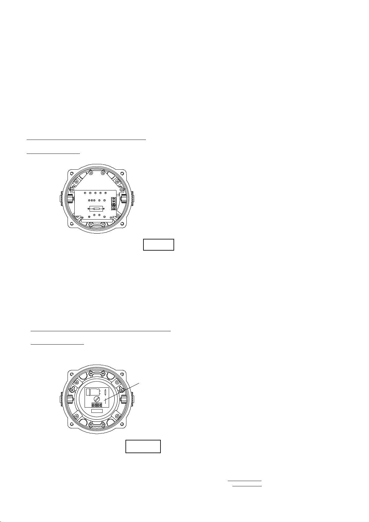
foraccessto theflameproofenclosure). Figures4and5
show theterminalsinthe flameproofenclosures forthe 100V
Lineandlowimpedanceunitsrespectively. Onthe low
impedanceunits caremustbetakenwiththepolarity of the
monitoringvoltage.