E2S E2xL15R User manual

European Safety Systems L
td.
Impress House,
Mansell Road, Acton, London
W3 7QH
www.e2s.com
Tel: +44 (0)208 743 8880
Document No. D209-00-101-IS
Issue 1
20-08-22
Sheet 1 of 5
INSTRUCTION MANUAL
E2xL15R, E2xL15F, E2xL25R, E2xL25F Loudspeakers
For use in Hazardous Locations
E2XL15R / E2XL25R E2XL15F E2XL25F
1) Product Table
2) Warnings
DO NOT OPEN WHEN AN EXPLOSIVE
ATMOSPHERE IS PRESENT
DO NOT OPEN WHEN ENERGISED
POTENTIAL ELECTROSTATIC CHARGING
HAZARD - CLEAN ONLY WITH A DAMP
CLOTH
HIGH VOLTAGE SHOCK HAZARD. WAIT 5
MINUTES AFTER REMOVING POWER
BEFORE OPENING THE ENCLOSURE
Avertissement:
NE PAS OUVRIR UN PRESENCE
D’ATMOSPHERE EXPLOSIVE
NE PAS OUVRIR ENERGIE
DANGER POTENTIEL CHARGE
ÉLECTROSTATIQUE - NETTOYER
UNIQUEMENT AVEC UN CHIFFON HUMIDE
HAUT TENSION, RISK DE CHOC.
ATTENDEZ 5 MINUTES APRES AVOIR
DEBRANCHE L’ALIMENTATION AVANT
D’OUVRIR LA BOITIER
3) Rating & Marking Information
3.1. ATEX / IECEx / UKEx certification
The E2xL15 and E2xL25 loudspeakers comply with the
following standards:
Standards
EN IEC 60079-0:2018 / IEC60079-0:2017 (Ed 7):
Explosive Atmospheres - Equipment. General Requirements
EN IEC 60079-7:2015 +A1:2018 / IEC 60079-7:2018 (Ed. 5.1):
Explosive Atmospheres - Equipment Protection by Increased
Safety "e"
EN 60079-31:2014 / IEC 60079-31:2013 (Ed 2):
Explosive Atmospheres - Equipment Dust Ignition Protection
by Enclosure "t"
Ratings
E2XL15:
Ex ec IIC T4 Gc Ta -20°C to +55°C
Ex tc IIIC T85°C Dc Ta -20°C to +55°C
E2XL25 : Ex ec IIC T2 Gc Ta -20°C to +55°C
Ex tc IIIC 85°C Dc Ta -20°C to +40°C
Ex tc IIIC 100°C Dc Ta -20°C to +55°C
Model
Input
Wattage
Max I/P Volts
E2xL15FV070 / E2xL15RV070 70V Line 15 70
E2xL25FV070 / E2xL25RV070 70V Line 25 70
E2xL15FV100 / E2xL15RV100 100V Line 15 100
E2xL25FV100 / E2xL25RV100 100V Line 25 100
E2xL15FR008 / E2xL15RR008 8 Ohm 15 10.95
E2xL25FR008 / E2xL25RR008 8 Ohm 25 14.14
E2xL15FR016 / E2xL15RR016 16 Ohm 15 15.49
E2xL25FR016 / E2xL25RR016 16 Ohm 25 20
Table 1: Electrical Ratings.

European Safety Systems L
td.
Impress House,
Mansell Road, Acton, London
W3 7QH
www.e2s.com
Tel: +44 (0)208 743 8880
Document No. D209-00-101-IS
Issue 1
20-08-22
Sheet 2 of 5
Certificate No. DEMKO 06ATEX 0421554X
IECEx ULD 14.0012X
UL21UKEX2135X
ATEX Mark, Equipment
Group and Category:
II 3G
II 3D
CE Marking
UKCA Marking
3.2. NEC & CEC Ratings
NEC & CEC Class / Division Ratings for US /
Canada
Standards
UL 121201-2021 (Ed. 9)
CAN/CSA C22.2 No. 213-17 (Ed. 3)
Ratings
E2XL15: Class I, Div 2, ABCD T3C Ta -20°C to +55°C
Class I, Div 2, ABCD T4 Ta -20°C to +40°C
Class II, Div 2, FG T6 Ta -20°C to +55°C
Class III, Div 1&2 Ta -20°C to +55°C
E2XL25: Class I, Div 2, ABCD T2C Ta -20°C to +55°C
Class I, Div 2, ABCD T2D Ta -20°C to +40°C
Class II, Div 2, FG T5 Ta -20°C to +55°C
Class II, Div 2, FG T6 Ta -20°C to +40°C
Class III, Div 1&2 Ta -20°C to +55°C
Installation must be carried out in compliance with the National
Electric Code / Canadian Electric Code
NEC Class / Zone ratings US
Standards
UL 60079-0 (Ed. 7):
Explosive Atmospheres - part 0: Equipment - General
Requirements
UL 60079-7 (Ed. 5):
Explosive Atmospheres - Equipment Protection by Increased
Safety "e"
UL 60079-31 (Ed. 2)
Explosive Atmospheres - Equipment Dust Ignition Protection
by Enclosure "t"
Ratings
E2XL15: Class I Zone 2 AEx ec IIC T4 Gc Ta -20°C to +55°C
Zone 22 AEx tc IIIC T85°C Dc Ta -20°C to +55°C
E2XL25: Class I Zone 2 AEx ec IIC T2 Gc Ta -20°C to +55°C
Zone 22 AEx tc IIIC 85°C Dc Ta -20°C to +40°C
Zone 22 AEx tc IIIC 100°C Dc Ta -20°C to +55°C
Installation must be carried out in compliance with the National
Electric Code.
CEC Class / Zone ratings Canada
S
tandards
CAN/CSA C22.2 No. 60079-0 (Ed. 4) 02/2019
Explosive Atmospheres - Part 0: Equipment - General
Requirements
CAN/CSA C22.2 No. 60079-7 (Ed. 2)
Explosive Atmospheres - Equipment Protection by Increased
Safety "e"
CAN/CSA C22.2 No. 60079-31 (Ed. 2)
Explosive Atmospheres - Equipment Dust Ignition Protection
by Enclosure "t"
Rating
E2XL15:: Ex ec IIC T4 Gc Ta -20°C to +55°C
Ex tc IIIC T85°C Dc Ta -20°C to +55°C
E2XL25: Ex ec IIC T2 Gc Ta -20°C to +55°C
Ex tc IIIC 85°C Dc Ta -20°C to +40°C
Ex tc IIIC 100°C Dc Ta -20°C to +55°C
Installation must be carried out in compliance with the Canadian
Electric Code
4) Zones, Gas Groups, Category and
Temperature Classification
When connected to an approved system the E2X alarm horn
may be installed in:
Area Cla
ssification
Zone 2
Explosive gas air mixture not likely to occur in
normal operation, and if it does, it will only
exist for a short time.
Zone 22
Explosive dust air mixture not likely to occur in
normal operation, and if it does, it will only
exist for a short time.
Gas Groupings
Group IIA Propane
Group IIB Ethylene
Group IIC Hydrogen and Acetylene
Temperature
Classification
for Gas Applications
T1 450ºC
T2 300ºC
T3 200ºC (E2XL15 Only)
T4 135°C (E2XL15 Only)
Dust Groupings
(ATEX / IECEx
/
UKEX
only)
Group IIIA Combustible Flyings
Group IIIB Non-conductive Dust
Group IIIC Conductive Dust
Maximum Surface Temperature for Dust Applications
(ATEX / IECEx
/ UKEX
only)
E2XL15:
85°C
E2XL25:
100°C
85°C (Only up to 40°C Ambient)

European Safety Systems L
td.
Impress House,
Mansell Road, Acton, London
W3 7QH
www.e2s.com
Tel: +44 (0)208 743 8880
Document No. D209-00-101-IS
Issue 1
20-08-22
Sheet 3 of 5
Equipment Category
3G / 3D
Equipment Level Protec
tion
Gc, Dc
Ambient
Temperature Range
-20°C to +55°C
IP Rating
IP6
4
to EN/IEC60079
-
0
IP66 to EN60529
To maintain the ingress protection rating, the two off cable entries
must be fitted with suitably rated, certified cable entry and/or
blanking devices during installation.
Type Rating
Per
UL50E / NEMA250:
4 / 4X / 3R / 13
Installation must be carried out in compliance with the latest
issue of the following standards:
EN60079-14 / IEC60079-14: Explosive atmospheres -
Electrical installations design, selection and erection
EN60079-10-1 / IEC60079-10-1: Explosive atmospheres -
Classification of areas. Explosive gas atmospheres
EN60079-10-2 / IEC60079-10-2: Explosive atmospheres –
Classification of areas. Explosive dust atmospheres
5) Special Conditions of Use
When used for a Group III application, the surface of the
enclosure may store electrostatic charge and become a
source of ignition in applications with a low relative humidity
<~30% relative humidity where the surface is relatively free of
surface contamination such as dirt, dust, or oil.
Guidance on protection against the risk of ignition due to
electrostatic discharge can be found in EN TR50404 and IEC
TR60079-32.
End user shall adhere to the manufacturer’s installation and
instruction when performing housekeeping to avoid the
potential for hazardous electrostatic charges during cleaning,
by using a damp cloth.
To maintain the ingress protection rating and mode of
protection, the cable entries must be fitted with suitably rated,
certified cable entry and/or blanking devices during
installation.
Equipment with the flare horn shall not be installed with the
flare higher than horizontal (to avoid accumulation of dust).
The equipment incorporates metal parts isolated from earth,
having capacitance values exceeding the limits permitted in
the standards of certification. Mounting bracket – 10.33pF.
6) Product Mounting and Access
6.1. Location and Mounting
The location of the loudspeaker should be made with due
regard to the area over which the warning signal must be
audible. They should only be fixed to services that can carry
the weight of the unit.
The E2x loudspeaker should be secured to any flat surface
using the three 7mm fixing holes on the stainless steel U
shaped mounting bracket. See Figure 1. The required angle
can be achieved by loosening the two large bracket screws in
the side of the unit, which allow adjustment of the
loudspeaker in steps of 18°. On completion of the installation
the two large bracket adjustment screws on the side of the
unit must be fully tightened to ensure that the unit cannot
move in service.
Fig. 1 Fixing Location for Loudspeaker L25 Flare
Fig. 1 Fixing Location for Loudspeaker L15 Flare
Fig. 1 Fixing Location for Loudspeaker Radial

European Safety Systems L
td.
Impress House,
Mansell Road, Acton, London
W3 7QH
www.e2s.com
Tel: +44 (0)208 743 8880
Document No. D209-00-101-IS
Issue 1
20-08-22
Sheet 4 of 5
6.2. Access to the Enclosure
Warning – High voltage may be
present, risk of electric shock.
DO NOT open when energised,
disconnect power before opening.
Warning – Hot surfaces. External
surfaces and internal components
may be hot after operation, take
care when handling the equipment.
To access the enclosure, remove the four M4 posi pan head
screws, M4 spring and plain washers and withdraw the cover.
Fig. 2 Accessing the Enclosure.
To replace cover, check that the ‘O’ ring seal is in place.
Carefully push the cover in place. Insert and tighten down M4
screws, spring and plain washers in the order shown above
and tighten down.
7. Selection of Cable. Cable Glands, Blanking
Elements & Adapters
When selecting the cable size, consideration must be given
to the input current that each unit draws (see Table 1), the
number of sounders on the line and the length of the cable
runs. The cable size selected must have the necessary
capacity to provide the input current to all of the sounders
connected to the line.
The dual entries can be ordered with one of the following
options:
2-off M20 x 1.5 thread
2-off ½” NPT thread
1-off M20 x 1.5 & 1-off ½” NPT thread
To maintain the ingress protection rating and mode of
protection, the cable entries must be fitted with suitably rated,
certified cable entry and/or blanking devices during
installation.
For ambient temperatures over +40ºC the cable entry
temperature may exceed +70ºC or the cable branching
temperature may exceed +80ºC. Therefore suitable heat
resisting cables and cable glands must be used as per table
below
Ambient Temp. 40ºC 45ºC 50ºC 55ºC
Min. Rating of cables
and cable glands 90ºC 95ºC 100ºC 105ºC
If a high IP (Ingress Protection) rating is required then a
suitable sealing washer must be fitted under the cable glands
or blanking plugs.
For use in explosive dust atmospheres, a minimum ingress
protection rating of IP6X must be maintained.
For use in explosive gas atmospheres, a minimum ingress
protection rating of IP54 must be maintained.
8. Cable Connections
Electrical connections are to be made into the terminal blocks
on the PCBA located in the enclosure. See section 5 of this
manual for access to the enclosure.
Wires having a cross sectional area between 0.5 mm² to
2.5mm² can be connected to each terminal way. If an input
and output wire is required the 2-off Live/Neutral or +/-
terminals can be used. If fitting 2-off wires to one terminal
way the sum of the 2-off wires must be a maximum cross
sectional area of 2.5mm². Strip wires to 8mm. Wires may also
be fitted using ferrules. Terminal screws need to be tightened
down with a tightening torque of 0.45 Nm / 4 Lb-in. When
connecting wires to the terminals great care should be taken
to dress the wires so that when the cover is inserted into the
chamber the wires do not exert excess pressure on the
terminal blocks. This is particularly important when using
cables with large cross sectional areas such as 2.5mm².
9. Line In Wiring
Refer to schematic document D209-06-101 for further detail
on terminal connections.
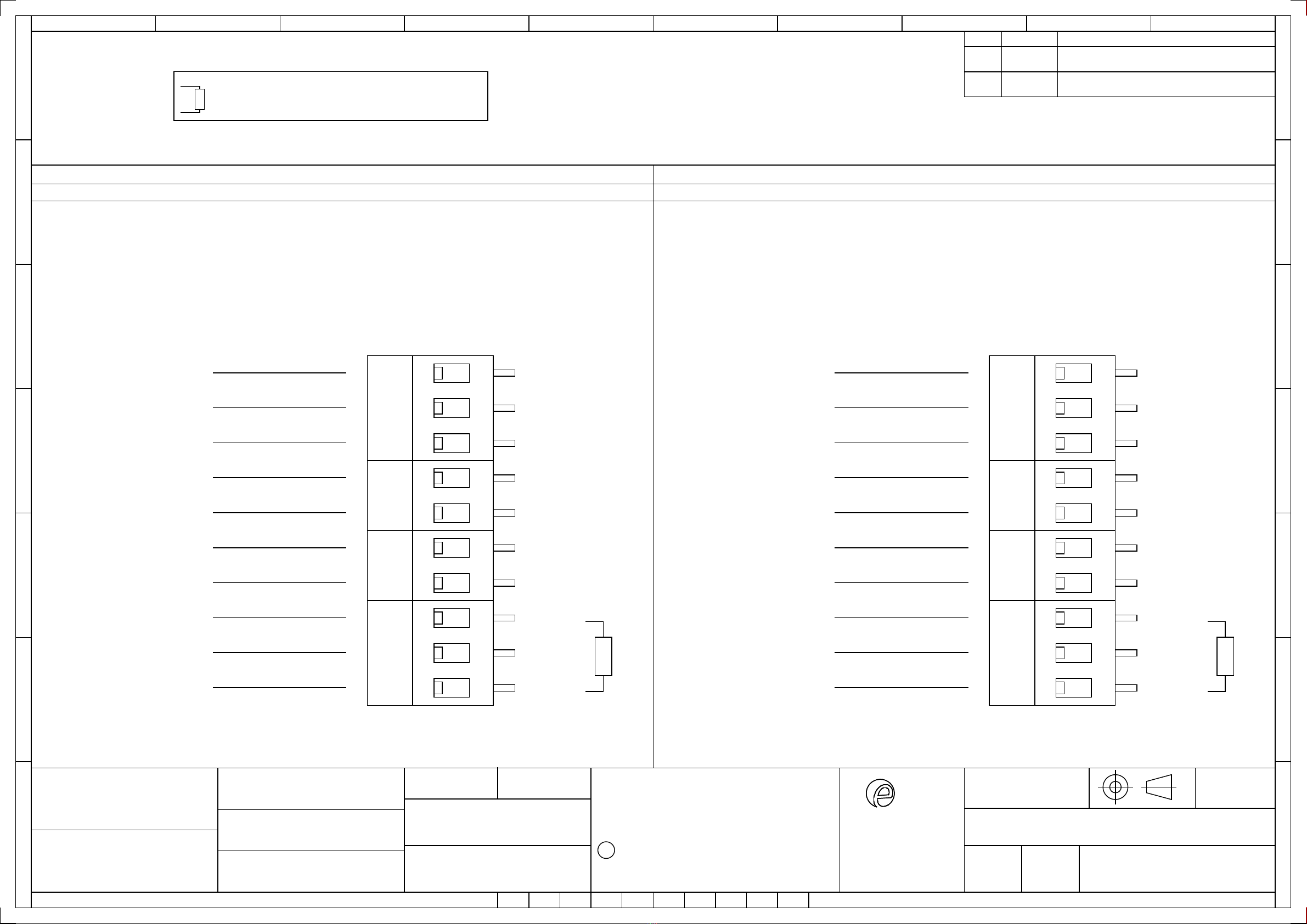
A 10-way terminal block is provided on the Line in
loudspeakers. There are 2-off Common, 2-off 15W/25W, 2-off
7.5W/12.5W, 2-off 3W/6W and 2-off 1W/2W terminals.
9.1 L15 PCBA Terminals
Fig. 4 L15 Line in Terminals
1W 3W 7.5W 15W C
(Appropriate cable entry devices
to
be
customer supplied
)
Cover
M4 Cover
Screw
M4 Spring
Washer
M4 Plain
Washer

European Safety Systems L
td.
Impress House,
Mansell Road, Acton, London
W3 7QH
www.e2s.com
Tel: +44 (0)208 743 8880
Document No. D209-00-101-IS
Issue 1
20-08-22
Sheet 5 of 5
15W COM
25W COM
9.2 L25 PCBA Terminals
Fig. 6 L25 Line in Terminals
9.3 Line Monitoring (Line in Units Only)
On E2xL15 & E2xL25 loudspeakers, DC line monitoring can
be used if required. All Line in Loudspeakers have a blocking
diode fitted in their supply input lines. It should be noted that
each loudspeaker has a 1M ohm bleed resistor connected
across the blocking capacitor and this should be taken into
account when selecting the value of the end of line
monitoring resistance. The end of line monitoring resistor can
be connected across the terminals on the end of line unit. If
an end of line resistor is used it must have the following
values:
Min. Resistance Min. Power
70V
Line
3.9KΩ 0.5W
1KΩ 2W
100V
Line
15KΩ 0.5W
3.9KΩ 2W
The resistor must be connected directly across the terminals.
Whilst keeping its leads as short as possible, a spacing of at
least 1/16” (1.58mm) must be provided through air and over
surfaces between uninsulated live parts.
10. Low Impedance Wiring
10.1 L15 Low Impedance
A 4-way terminal block is provided on the Low Impedance
Loudspeakers. There are 2-off Common and 2-off 15W/25W
terminals in total.
For further detail, refer to schematic document D209-06-101
Fig. 8 L15 Low Impedance Terminals
10.2 L25 Low Impedance
Fig. 10 L25 Low Impedance Terminals
11. Maintenance, Overhaul & Repair
Maintenance, repair and overhaul of the equipment should
only be carried out by suitably qualified personnel in
accordance with the current relevant standards:
EN60079-19
IEC60079-19
Explosive atmospheres - Equipment repair,
overhaul and reclamation
EN 60079-17
IEC60079-17
Explosive atmospheres - Electrical
installations inspection and maintenance
To avoid a possible ELECTROSTACTIC CHARGE the unit
must only be cleaned with a damp cloth.
Units must not be opened while an explosive atmosphere is
present.
If opening the unit during maintenance operations a clean
environment must be maintained and any dust layer removed
prior to opening the unit.
2W 6W 12.5W 25W C

warning signals
2S
Ex N
EUROPEAN SAFETY SYSTEMS LTD
IMPRESS HOUSE
MANSELL ROAD
ACTON
LONDON W3 7QH
WWW.E2S.COM
C
THIS DRAWING AND ANY INFORMATION OR DESCRIPTIVE
MATTER THEREIN IS COMMUNICATED IN CONFIDENCE AND
IS THE COPYRIGHT PROPERTY OF EUROPEAN SAFETY
SYSTEMS LTD. NEITHER THE WHOLE OR ANY EXTRACT MAY
BE DISCLOSED, LOANED, COPIED OR USED FOR
MANUFACTURING OR TENDERING PURPOSES WITHOUT THEIR
WRITTEN CONSENT.
EUROPEAN SAFETY SYSTEMS LTD.
AS PER LATEST DATE OF ISSUE SHOWN ABOVE
DRAWING TO BS8888:2000
GEOMETRIC TOLERANCES TO ISO1101:1983
LINEAR DIMENSIONAL TOLS
ANGULAR DIMENSIONAL TOLS
STANDARDS
MOD No. REASON - INITIAL - DATEISSUE
DATE
APPROVED
CHECKED DATE
DATE
DRAWN WEIGHT (Kg)
SURFACE FINISH
MATERIAL
ALTERNATIVE MATERIAL SHEETSCALE
TITLE
A3
IF IN DOUBT, ASK -
DO NOT SCALE
ALL DIMENSIONS IN MM
DRAWING NUMBER
A
B
C
D
E
F
G
109
G
F
E
78
6
5
D
C
134
2
A
B
D209-06-101
R.S.RAIT
R.N.POTTS
R.N.POTTS
05/08/2020
OF
E2xL15, E2xL25
LOUDSPEAKER WIRING DIAGRAMS
INTRODUCTION
RSR - 05/08/2020
NTS 1 2
A
05/08/2020
05/08/2020
7.5W
7.5W
3W
3W
1W
1W
C
C
1W OUT
3W IN
3W OUT
7.5W IN
15W
15W
E2XL15V070 / E2XL15V100 LINE-IN UNITS 70V / 100V
Line Monitoring
E2XL25V070 / E2XL25V100 LINE-IN UNITS 70V / 100V
Line Monitoring
OPTIONAL LINE MONITORING RESISTOR, CUSTOMER SUPPLIED,
REQUIRED MINIMUM VALUES:
R1
70V LINE-IN: 1KΩ MIN, 2W MIN OR 3K9Ω MIN, 0.5W MIN
100V LINE-IN: 3.9KΩ MIN, 2W MIN OR 15KΩ MIN, 0.5W MIN
1W IN
7.5W OUT
R1
15W IN
15W OUT
COMMON
COMMON
12.5W
12.5W
6W
6W
2W
2W
C
C
2W OUT
6W IN
6W OUT
12.5W IN
25W
25W
2W IN
12.5W OUT
25W IN
25W OUT
COMMON
COMMON
R1
FORMAT UPDATED
DH - 17/05/2022
B

warning signals
2S
Ex N
EUROPEAN SAFETY SYSTEMS LTD
IMPRESS HOUSE
MANSELL ROAD
ACTON
LONDON W3 7QH
WWW.E2S.COM
C
THIS DRAWING AND ANY INFORMATION OR DESCRIPTIVE
MATTER THEREIN IS COMMUNICATED IN CONFIDENCE AND
IS THE COPYRIGHT PROPERTY OF EUROPEAN SAFETY
SYSTEMS LTD. NEITHER THE WHOLE OR ANY EXTRACT MAY
BE DISCLOSED, LOANED, COPIED OR USED FOR
MANUFACTURING OR TENDERING PURPOSES WITHOUT THEIR
WRITTEN CONSENT.
EUROPEAN SAFETY SYSTEMS LTD.
AS PER LATEST DATE OF ISSUE SHOWN ABOVE
DRAWING TO BS8888:2000
GEOMETRIC TOLERANCES TO ISO1101:1983
LINEAR DIMENSIONAL TOLS
ANGULAR DIMENSIONAL TOLS
STANDARDS
MOD No. REASON - INITIAL - DATEISSUE
DATE
APPROVED
CHECKED DATE
DATE
DRAWN WEIGHT (Kg)
SURFACE FINISH
MATERIAL
ALTERNATIVE MATERIAL SHEETSCALE
TITLE
A3
IF IN DOUBT, ASK -
DO NOT SCALE
ALL DIMENSIONS IN MM
DRAWING NUMBER
A
B
C
D
E
F
G
109
G
F
E
78
6
5
D
C
134
2
A
B
D209-06-101
R.S.RAIT
R.N.POTTS
R.N.POTTS
05/08/2020
OF
E2xL15, E2xL25
LOUDSPEAKER WIRING DIAGRAMS
INTRODUCTION
RSR - 05/08/2020
NTS 2 2
A
05/08/2020
05/08/2020
C
C
15W
15W
E2XL15R008 / E2XL15R016 LOW IMPENDENCE UNITS 8-OHM / 16-OHM E2XL25R008 / E2XL25R016 LOW IMPENDENCE UNITS 8-OHM / 16-OHM
15W IN
15W OUT
COMMON
COMMON
C
C
25W
25W
25W IN
25W OUT
COMMON
COMMON
FORMAT UPDATED
DH - 17/05/2022
B

E2S Telephone: +44 (0)20 8743 8880 Fax: +44 (0)20 8740 4200 Email: [email protected] www.e2s.com DC-062_Issue_I (E2x).docx - Page 1 of 2 - QAF_252_Issue_5
EU Declaration of Conformity
Manufacturer: European Safety Systems Ltd.
Impress House, Mansell Road, Acton
London, W3 7QH
United Kingdom
Authorised Representative: E2S Warnsignaltechnik UG
Charlottenstrasse 45-51
72764 Reutlingen
Germany
Equipment Type: E2xS1, E2xS2
E2xB05, E2xB10, E2xBL2
E2xC1X05, E2xC1LD2,
E2xL15, E2xL25
Directive 2014/34/EU: Equipment and Protective Systems for use in Potentially Explosive Atmospheres (ATEX)
Notified Body for EU
type Examination
(Module B)
:
UL International Demko A/S
Notified Body No.: 0539
Borupvang 5A, 2750 Ballerup, Denmark
EU
-
type Examination Certificate
(Module B)
:
DEMKO 06 ATEX 0421554X
Notified Body for Quality Assurance Notification /
Conformity to EU
-
type
based on
quality assurance of the production process (Module D):
Sira Certification Service
Notified Body No.: 2813
CSA Group Netherlands B.V, Utrechtseweg 310, 6812 AR, Arnhem, Netherlands
Quality Assurance Notification
(Module D)
:
SIRA 05 ATEX M342
Provisions fulfilled by the equipment:
II 3G Ex
ec
IIC T4/T3/T2 Gc
II 3D Ex tc IIIC 85°C…120°C Dc
IP6X Dust Protection to EN60079-0 / EN60079-31
Standards applied:
EN IEC 60079
-
0:2018
EN IEC 60079-7:2015 +A1:2018
EN 60079-31:2014
Directive 2014/30/EU: Electromagnetic Compatibility Directive (EMC)
Standards applied:
EN 61000
-
6
-
1:2007
EN 61000-6-2:2005
EN 61000-6-3:2007 / A1:2011 / AC: 2012
EN 61000-6-4:2007 / A1: 2011
Directive 2014/35/EU: Low Voltage Directive (LVD)
Standards applied:
EN 60947
-
1:2007 + A2:2014
Directive 2011/65/EU: Restriction of the use of certain hazardous substances in electrical and electronic equipment (RoHS)
The product and all the components contained within it are in accordance with the restriction of the use of hazardous substances in electrical and electronic
equipment, including amendment by Directive 2015/863/EU.
Regulation (EC) 1907/2006: Registration, Evaluation, Authorisation and Restriction of Chemicals (REACH)
The product and all the components contained within it are free from substances of very high concern.
Other Standards and Regulations
EN 60529:1992+A2:2013 - Degrees of protection provided by enclosures (IP code) – enclosure rated IP66/IP67

E2S Telephone: +44 (0)20 8743 8880 Fax: +44 (0)20 8740 4200 Email: [email protected] www.e2s.com DC-062_Issue_I (E2x).docx - Page 2 of 2 - QAF_252_Issue_5
Martin Streetz Document No.: DC-062_Issue_I
Quality Assurance Manager Date and Place of Issue: London, 22/08/2022
EU Declaration of Conformity
On behalf of European Safety Systems Ltd., I declare that, on the date the equipment accompanied by this declaration is placed on the market, the equipment
conforms with all technical and regulatory requirements of the above listed directives, regulations and standards.
This Declaration is issued under the sole responsibility of the manufacturer.

E2S Telephone: +44 (0)20 8743 8880 Fax: +44 (0)20 8740 4200 Email: [email protected] www.e2s.com DC-103_Issue_A - Page 1 of 2 - QAF_252_Issue_5
UKCA Declaration of Conformity
Manufacturer: European Safety Systems Ltd.
Impress House, Mansell Road, Acton
London, W3 7QH
United Kingdom
Equipment Type: E2xS1, E2xS2
E2xB05, E2xB10, E2xBL2
E2xC1X05, E2xC1LD2,
E2xL15, E2xL25
Directive UKSI 2016:1107 (as amended by UKSI 2019:696) – Schedule 3A, Part 1 : Product or Protective System Intended for use in Potentially Explosive Atmospheres
(UKCA)
Notified Body for
UK
type Examination
(Module B)
:
UL International (UK) Ltd
Notified Body No.: 0843
Unit 1‐3 Horizon Kingsland Business Park, Wade Road,
Basingstoke, Hampshire RG24 8AH UK
UK
‐
type Examination Certificate
(Module B)
:
UL21UKEX2135X
Notified Body for Quality Assurance Notification / Conformity to EU
‐
type
based on
quality assurance of the production process (Module D):
Sira Certification Service
Notified Body No.: 0518
Rake Lane, Eccleston, Chester CH4 9JN, UK
Quality Assurance Notification
(Module D)
:
CSAE 22UKQAN0046
Provisions fulfilled by the equipment:
II 3G Ex
ec
IIC T4/T3/T2 Gc
II 3D Ex tc IIIC 85°C…120°C Dc
IP6X Dust Protection to EN60079‐0 / EN60079‐31
Standards applied:
EN IEC 60079
‐
0:2018
EN IEC 60079‐7:2015 +A1:2018
EN 60079‐31:2014
Directive 2014/30/EU: Electromagnetic Compatibility Directive (EMC)
Standards applied:
EN 61000
‐
6
‐
1:2007
EN 61000‐6‐2:2005
EN 61000‐6‐3:2007 / A1:2011 / AC: 2012
EN 61000‐6‐4:2007 / A1: 2011
Directive 2014/35/EU: Low Voltage Directive (LVD)
Standards applied:
EN
60947
‐
1:2007 + A2:2014
Directive 2011/65/EU: Restriction of the use of certain hazardous substances in electrical and electronic equipment (RoHS)
The product and all the components contained within it are in accordance with the restriction of the use of hazardous substances in electrical and electronic
equipment, including amendment by Directive 2015/863/EU.
Regulation (EC) 1907/2006: Registration, Evaluation, Authorisation and Restriction of Chemicals (REACH)
The product and all the components contained within it are free from substances of very high concern.
Other Standards and Regulations
EN 60529:1992+A2:2013 ‐ Degrees of protection provided by enclosures (IP code) – enclosure rated IP66/IP67

E2S Telephone: +44 (0)20 8743 8880 Fax: +44 (0)20 8740 4200 Email: [email protected] www.e2s.com DC-103_Issue_A - Page 2 of 2 - QAF_252_Issue_5
Martin Streetz Document No.: DC‐103_Issue_A
Quality Assurance Manager Date and Place of Issue: London, 22/08/2022
UKCA Declaration of Conformity
On behalf of European Safety Systems Ltd., I declare that, on the date the equipment accompanied by this declaration is placed on the market, the equipment
conforms with all technical and regulatory requirements of the above listed directives, regulations and standards.
This Declaration is issued under the sole responsibility of the manufacturer.
Other manuals for E2xL15R
1
This manual suits for next models
19
Table of contents
Other E2S Speakers manuals