E2S STExL1 Series User manual

INSTRUCTION MANUAL (ATEX / IECEx & UKEx)
STExL1 & STExL2
Loudspeakers
For use in Flammable Gas and Dust Atmospheres
E2S Warning Signals Impress House, Mansell Road, Acton, London W3 7QH
www.e2s.com
Tel: +44 (0)208 743 8880
Document No. D199-00-101-IS
Issue 3
21-10-22
Sheet 1 of 4
1) Warnings
•DO NOT OPEN WHEN AN EXPLOSIVE
ATMOSPHERE IS PRESENT
•POTENTIAL ELECTROSTATIC CHARGING
HAZARD
•ALL ENTRIES M20 X 1.5 - IF TEMPERATURE
EXCEEDS 70°C AT ENTRY OR 80°C AT
BRANCHING POINT USE SUITABLE RATED
CABLE AND CABLE GLANDS
2) Rating & Marking Information
All units have a rating label, which carries the following
important information:-
Input Voltage:
Low Impedance Units 8Ω or 16Ω
Line Voltage Units 70Vline or 100V line
STExL1 Codes:
Ex db IIC Gb T6 Ta -50°C to +55°C
Ex db IIC Gb T5 Ta -50°C to +70°C
Ex tb IIIC Db T95°C Ta -50°C to +70°C
STExL2 Codes:
Ex db IIC Gb T6 Ta -50°C to +45°C
Ex db IIC Gb T5 Ta -50°C to +60°C
Ex db IIC Gb T4 Ta -50°C to +70°C
Ex tb IIIC Db T105°C Ta -50°C to +70°C
Certificate No.
DEMKO 16 ATEX 1466X
IECEx ULD 16.0017X
UL21UKEX2019X
Epsilon x
Equipment Group and
Category:
II 2G
II 2D
CE Marking
Notified Body No
2813
UKCA Marking and
Notified Body No.
0518
The units can be installed in locations with the following
conditions:
Area Classification Gas:
Zone 1
Explosive gas air mixture likely to occur in
normal operation.
Zone 2
Explosive gas air mixture not likely to occur
in normal operation, and if it does, it will only
exist for a short time.
Gas Groupings:
Group IIA
Propane
Group IIB
Ethylene
Group IIC
Hydrogen and Acetylene
Temperature Classification:
T1
450ºC
T2
300ºC
T3
200ºC
T4
135ºC
T5
100ºC (up to 60ºC ambient for STExL2
only)
T6
85ºC (up to 55ºC ambient for STExL1, up
to 45ºC ambient for STExL2 only)
Area Classification Dust:
Zone 21
Explosive dust air mixture likely to occur in
normal operation.
Zone 22
Explosive dust air mixture not likely to occur
in normal operation, and if it does, it will only
exist for a short time.
Dust Groupings:
Group IIIA
Combustible Flyings
Group IIIB
Non-conductive Dust
Group IIIC
Conductive Dust
Ambient Temperature Range: -50°C to +70°C
IP Rating: IP66 to EN/IEC60079-0 and EN/IEC60529
Equipment Category: 2G/D
Equipment Protection Level: Gb, Gc, Db, Dc
Maximum Surface Temperature for Dust Applications:
95ºC (STExL1)
105ºC (STExL2)
STExL1
STExL2

E2S Warning Signals Impress House, Mansell Road, Acton, London W3 7QH
www.e2s.com
Tel: +44 (0)208 743 8880
Document No. D199-00-101-IS
Issue 3
21-10-22
Sheet 2 of 4
3) Type Approval Standards
The equipment carries an EC & UKCA Type Examination
Certificate and IECEx Certificate of Conformity, and have been
certified to comply with the following standards:
EN60079-0:2018/ IEC60079-0:2017 (Ed 7):
Explosive Atmospheres - Equipment. General requirements
EN60079-1:2014 / IEC60079-1:2014 (Ed 7): Explosive
Atmospheres - Equipment protection by flameproof
enclosures "d"
EN 60079-31:2014 / IEC 60079-31:2013 (Ed 2): Explosive
Atmospheres - Equipment dust ignition protection by
enclosure "t"
4) Installation Requirements
The loudspeaker must only be installed by suitably qualified
personnel in accordance with the latest issues of the relevant
standards:
EN60079-14 / IEC60079-14: Explosive atmospheres -
Electrical installations design, selection and erection
EN60079-10-1 / IEC60079-10-1: Explosive atmospheres -
Classification of areas. Explosive gas atmospheres
EN60079-10-2 / IEC60079-10-2: Explosive atmospheres -
Classification of areas. Explosive dust atmospheres
The installation of the units must also be in accordance with
any local codes that may apply and should only be carried out
by a competent electrical engineer who has the necessary
training.
5) Special Conditions of Use
Repair of the flamepath / flameproof joints is not permitted.
The plastic horn is not anti-static and the metallic enclosure
has a non-conductive coating. These may generate an
ignition-capable level of electrostatic charges under certain
extreme conditions. The user should ensure that the
equipment is not installed in a location where it may be
subjected to external conditions that might cause a build-up of
electrostatic charges on non-conducting surfaces.
Additionally, cleaning of the equipment should be done only
with a damp cloth.
6) Location and Mounting
The location of the loudspeaker should be made with due
regard to the area over which the warning signal must be
visible/audible. They should only be fixed to surfaces that can
carry the weight of the unit.
The STEx loudspeaker should be secured to any flat surface
using the three 7mm fixing holes. The angle can then be
adjusted as required but the mounting restrictions must be
observe. See Fig 1c. This can be achieved by loosening the
two large bracket screws in the side of the unit, which allow
adjustments in steps of 18°. The enclosure provides IP66
protection and is suitable for installation in exterior locations
providing it is positioned so that water cannot collect in the
horn, and the cable entry is sealed. See figure 1.
Fig 1a. Fixing Location for Small Horn
Fig 1b. Fixing Location for Large Horn
Fig. 1c Mounting Restrictions
7) Access to the Flameproof Enclosure
In order to connect the electrical supply cables to the
loudspeaker it is necessary to remove the flameproof cover to
gain access to the flameproof chamber. To access the Ex d
chamber, loosen the M4 grub screw on the loudspeaker cover.
Open the enclosure by turning the loudspeaker cover
counterclockwise and remove the cover, taking extreme care
not to damage the flameproof threads in the process (See
figure 2).
Fig. 2 Accessing the Explosion proof Enclosure.
Warning –High voltage may be present, risk
of electric shock. DO NOT open when
energised, disconnect power before
opening.
Warning –Hot surfaces. External surfaces
and internal components may be hot after
operation, take care when handling the
equipment.
(Appropriate
cable glands to
be customer
supplied)
Flameproof cover
Grub screw

E2S Warning Signals Impress House, Mansell Road, Acton, London W3 7QH
www.e2s.com
Tel: +44 (0)208 743 8880
Document No. D199-00-101-IS
Issue 3
21-10-22
Sheet 3 of 4
On completion of the installation, the flameproof threaded joint
should be inspected to ensure that they are clean and that they
have not been damaged during installation. Repair of the
flamepath / flameproof joints is not permitted. Also check that
the ‘O’ ring seal is in place. When fitting the flameproof cover
ensure the thread is engaged correctly. Fully tighten the cover
all the way, ensure no gap is visible between the cover and
base of the loudspeaker enclosure. Tighten the M4 grub
screw.
8) Power Supply Selection
It is important that a suitable power supply is used to run the
loudspeaker. The power supply selected must have the
necessary capacity to provide the input current to all of the
loudspeakers
The following table shows the input current taken by the
various loudspeakers:
A supply voltage variation of +/-10% outside the voltage range
is permissible.
Nominal current at nominal voltage
Max rated current at worst case supply voltage and flash rate.
9) Selection of Cable. Cable Glands, Blanking
Elements & Adapters
When selecting the cable size, consideration must be given to
the input current that each unit draws (see table above), the
number of loudspeaker on the line and the length of the cable
runs. The cable size selected must have the necessary
capacity to provide the input current to all of the loudspeakers
connected to the line.
For ambient temperatures over +40ºC the cable entry
temperature may exceed +70ºC and therefore suitable heat
resisting cables and cable glands must be used as per table
below
STExL1:
Ambient
Temp.
45ºC
50ºC
55ºC
60ºC
65ºC
70ºC
Min. Rating
of cables
and cable
glands
70ºC
75ºC
80ºC
85ºC
90ºC
95ºC
STExL2:
Ambient
Temp.
40ºC
45ºC
50ºC
55ºC
60ºC
65ºC
70ºC
Min. Rating
of cables
and cable
glands
75ºC
80ºC
85ºC
90ºC
95ºC
100ºC
105ºC
The cable entries have an M20 x 1.5 –6H entry thread. If the
installation is made using cable glands, only suitably rated and
ATEX / IECEx & UKEx certified cable glands must be used.
They must be suitable for the type of cable being used and
also meet the requirements of the current installation
standards EN 60079-14 / IEC60079-14.
Any unused cable entries must be closed with suitably rated
and ATEX / IECEx & UKEx certified blanking plugs.
If the installation is made using conduit, openings must have a
sealing fitting connected as close as practical to the wall of the
enclosure, but in no case more than the size of the conduit or
50mm, whichever is the lesser.
If a high IP (Ingress Protection) rating is required then a
suitable sealing washer must be fitted under the cable glands
or blanking plugs. A minimum ingress protection rating of IP6X
must be maintained for installations in explosive dust
atmospheres.
For combustible dust applications, the cable entry device and
blanking elements shall be in type of explosion protection and
shall have an IP 6X rating.
The STEx loudspeaker range can be supplied with the
following types of adapters:
M20 to ½” NPT
M20 to ¾” NPT
M20 to M25
It is important to note that stopping plugs cannot be fitted onto
adapters, only directly onto the M20 entries.
Any other adapters used must be suitably rated and ATEX /
IECEx & UKEx certified adapters.
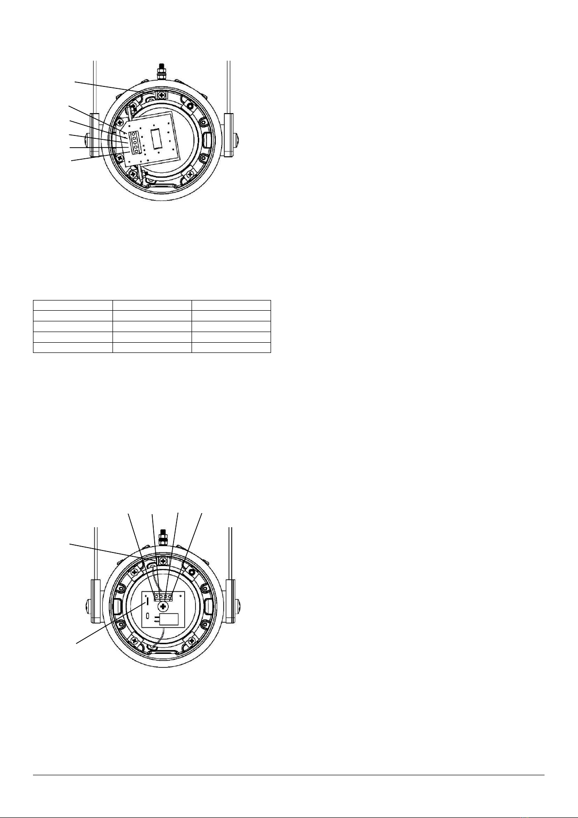
10) Earthing
Both AC and DC loudspeaker units must be connected to an
earth according to EN/IEC 60079/14. The units are provided
with internal and external earth terminals which are both
located on the terminal chamber section of the unit
Internal earthing connections should be made to the Internal
Earth terminal in the base of the housing using a ring crimp
terminal to secure the earth conductor under the earth clamp.
The earth conductor should be at least equal in size and rating
to the incoming power conductors.
External earthing connections should be made to the M5 earth
stud, using a ring crimp terminal to secure the earth conductor
to the earth stud. The external earth conductor should be at
least 4mm2 in size.
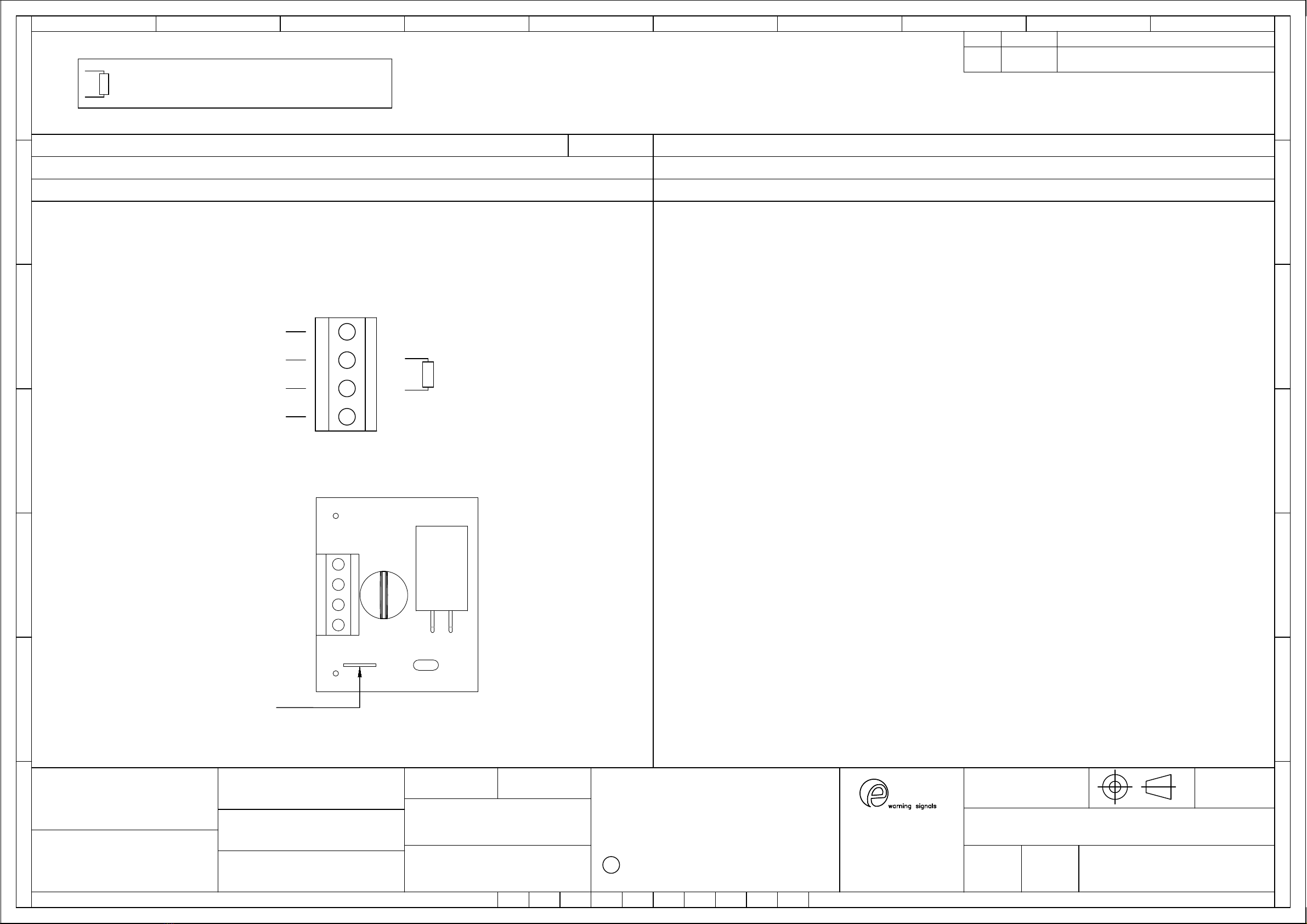
11) Cable Connections
Electrical connections are to be made into the terminal blocks
on the PCBA located in the flameproof enclosure. See section
7 of this manual for access to the flameproof enclosure.
Wires having a cross sectional area between 0.5 mm² to
2.5mm² can be connected to each terminal way. If an input and
output wire is required the 2-off Live/Neutral or +/- terminals
can be used. If fitting 2-off wires to one terminal way the sum
of the 2-off wires must be a maximum cross sectional area of
2.5mm². Strip wires to 8mm. Wires may also be fitted using
ferrules. Terminal screws need to be tightened down with a
tightening torque of 0.45 Nm / 5 Lb-in. When connecting wires
to the terminals great care should be taken to dress the wires
so that when the cover is inserted into the chamber the wires
do not exert excess pressure on the terminal blocks. This is
particularly important when using cables with large cross
sectional areas such as 2.5mm².
Model No.
Input
Power
(Watts)
Max. I/P
Volts
STExL1R008
8Ohm
15
10.95
STExL1R016
16Ohm
15
15.49
STExL1V070
70V Line
15
70
STExL1V100
100V Line
15
100
STExL2R008
8Ohm
25
14.14
STExL2R016
16Ohm
25
20
STExL2V070
70V Line
25
70
STExL2V100
100V Line
25
100

E2S Warning Signals Impress House, Mansell Road, Acton, London W3 7QH
www.e2s.com
Tel: +44 (0)208 743 8880
Document No. D199-00-101-IS
Issue 3
21-10-22
Sheet 4 of 4
12) 70V & 100V Line In Wiring
Fig. 3 Line in Terminals
The cable connections are made into the terminal blocks on
the PCB assembly located in the explosion proof enclosure.
See section 7 of this manual for access to the explosion proof
enclosure. The 70V & 100V Line loudspeakers are fitted with
a five way terminal block. Terminal A is common and one of
the other terminals B, C, D or E should be selected depending
on what output level is required (see table below).
Terminals
STExL2 (25W)
STExL1 (15W)
A - B
25W
15W
A - C
12.5W
7.5W
A - D
6W
3W
A - E
2W
1W
Refer to D199-06-101 for schematic diagram.
A single wire with a cross sectional area of up to 2.5mm² /
AWG14 can be connected to each terminal way or if an input
and output wire is required two wires can be connected to each
terminal way when crimped with a ferrule. If more than one
wire is fitted into a terminal a ferrule should be used to secure
the wires. When connecting wires to the terminals great care
should be taken to dress the wire so that when the cover is
inserted into the chamber the wires do not exert excess
pressure on the terminal blocks.
13) Low Impedance Wiring
Fig. 4 Low Impedance Terminals
STExL2 and STExL1 8Ωand 16Ωlow impedance
loudspeakers have dual input terminals on the PCB assembly
for input and output wiring. A cable of up to 4.0mm² can be
connected to each terminal. If DC line monitoring is used cut
the link on the board (see Fig. 4).
Refer to D199-06-101 for schematic diagram.
14) End of Line DC Monitoring
On GNExL2 and GNExL1 loudspeakers, dc line monitoring
can be used if required. Both the 70V and 100V Line units and
the Low Impedance units have blocking capacitors fitted. It
should be noted that each loudspeaker has a 1M ohm bleed
resistor connected across the blocking capacitor and this
should be taken into account when selecting the value of the
end of line monitoring resistance.
The end of line monitoring resistor can be connected across
the terminals on the end of line unit. On the low impedance
units care must be taken with the polarity of the monitoring
voltage.
On 100V and 70V line units the end of line resistor used must
have a minimum resistance value of 4k7 ohms and a minimum
wattage of 2.5 watts
On low impedance units the end of line resistor used must
have a minimum resistance value of 2k ohms and a minimum
wattage of 0.5 watts or a minimum resistance value of 500
ohms and a minimum wattage of 2 watts. On the low
impedance units care must be taken with the polarity of the
monitoring voltage. If an end of line resistor is fitted to a unit
the links on the printed circuit boards of all loudspeakers in the
line must be cut for the dc blocking capacitors to be in circuit
in order to dc monitor the line (see figure 5).
Refer to D199-06-101 for schematic diagram.
15) Maintenance, Overhaul and Repair
Maintenance, repair and overhaul of the equipment should
only be carried out by suitably qualified personnel in
accordance with the current relevant standards:
EN60079-19/IEC60079-19
Explosive atmospheres –Equipment repair, overhaul and
reclamation
EN 60079-17/IEC60079-17
Explosive atmospheres –Electrical installations inspection
and maintenance
Units must not be opened while an explosive atmosphere is
present.
If opening the unit during maintenance operations a clean
environment must be maintained and any dust layer removed
prior to opening the unit.
Flameproof threaded joints and cemented joints are not
permitted to be repaired.
Electrostatic charging hazard - Clean only with a damp cloth.
A
B
C
D
E
Internal Earth
Terminal
Internal Earth
Terminal
DC Line
Monitoring Link
+
+
-
-

2S
EUROPEAN SAFETY SYSTEMS LTD
IMPRESS HOUSE
MANSELL ROAD
ACTON
LONDON W3 7QH
WWW.E2S.COM
C
THIS DRAWING AND ANY INFORMATION OR DESCRIPTIVE
MATTER THEREIN IS COMMUNICATED IN CONFIDENCE AND
IS THE COPYRIGHT PROPERTY OF EUROPEAN SAFETY
SYSTEMS LTD. NEITHER THE WHOLE OR ANY EXTRACT MAY
BE DISCLOSED, LOANED, COPIED OR USED FOR
MANUFACTURING OR TENDERING PURPOSES WITHOUT THEIR
WRITTEN CONSENT.
EUROPEAN SAFETY SYSTEMS LTD.
AS PER LATEST DATE OF ISSUE SHOWN ABOVE
DRAWING TO BS8888:2000
GEOMETRIC TOLERANCES TO ISO1101:1983
LINEAR DIMENSIONAL TOLS
ANGULAR DIMENSIONAL TOLS
STANDARDS
MOD No. REASON - INITIAL - DATEISSUE
DATE
APPROVED
CHECKED DATE
DATE
DRAWN WEIGHT (Kg)
SURFACE FINISH
MATERIAL
ALTERNATIVE MATERIAL SHEETSCALE
TITLE
A3
IF IN DOUBT, ASK -
DO NOT SCALE
ALL DIMENSIONS IN MM
DRAWING NUMBER
A
B
C
D
E
F
G
109
G
F
E
78
6
5
D
C
134
2
A
B
D199-06-101
M.ABALOS
R.N.POTTS
R.N.POTTS
01/11/2022
OF
NTS 13
1INTRODUCTION
MA 01/11/2022
STExL1 & STExL2 LINE IN & LOW IMPEDANCE
LOUDSPEAKER WIRING DIAGRAMS
STExL1
STExL2
COMMON
LINE IN
OPTIONAL LINE MONITORING RESISTOR, CUSTOMER SUPPLIED,
4K7Ω MIN, 2.5W MIN
MINIMUM VALUE:
R1
R1
01/11/2022
01/11/2022
A (COM)
B (15W)
C (7.5W)
D (3W)
E (1W)
STExL1V070 & STExL1V100 Line in
Optional Line Monitoring
15W: Apply Signal to Common & 15W
STExL1V070 & STExL1V100 Line in
Optional Line Monitoring
7.5W: Apply Signal to Common & 7.5W
STExL1V070 & STExL1V100 Line in
Optional Line Monitoring
3W: Apply Signal to Common & 3W
STExL1V070 & STExL1V100 Line in
Optional Line Monitoring
1W: Apply Signal to Common & 1W
Config.: 1a Config.: 1b Config.: 1c Config.: 1d
A (COM)
B (15W)
C (7.5W)
D (3W)
E (1W)
A (COM)
B (15W)
C (7.5W)
D (3W)
E (1W)
A (COM)
B (15W)
C (7.5W)
D (3W)
E (1W)
R1
R1
R1
COMMON
LINE IN
COMMON
LINE IN
COMMON
LINE IN
TERMINAL
CONNECTIONS
STExL1V070
MAX. INPUT
VOLTAGE
OUTPUT
LEVEL
STExL1V100
70V
100V
A-B 15W
TERMINAL
CONNECTIONS
STExL1V070
MAX. INPUT
VOLTAGE
OUTPUT
LEVEL
STExL1V100
70V
100V
A-C 7.5W
TERMINAL
CONNECTIONS
STExL1V070
MAX. INPUT
VOLTAGE
OUTPUT
LEVEL
STExL1V100
70V
100V
A-D 3W
TERMINAL
CONNECTIONS
STExL1V070
MAX. INPUT
VOLTAGE
OUTPUT
LEVEL
STExL1V100
70V
100V
A-E 1W

2S
EUROPEAN SAFETY SYSTEMS LTD
IMPRESS HOUSE
MANSELL ROAD
ACTON
LONDON W3 7QH
WWW.E2S.COM
C
THIS DRAWING AND ANY INFORMATION OR DESCRIPTIVE
MATTER THEREIN IS COMMUNICATED IN CONFIDENCE AND
IS THE COPYRIGHT PROPERTY OF EUROPEAN SAFETY
SYSTEMS LTD. NEITHER THE WHOLE OR ANY EXTRACT MAY
BE DISCLOSED, LOANED, COPIED OR USED FOR
MANUFACTURING OR TENDERING PURPOSES WITHOUT THEIR
WRITTEN CONSENT.
EUROPEAN SAFETY SYSTEMS LTD.
AS PER LATEST DATE OF ISSUE SHOWN ABOVE
DRAWING TO BS8888:2000
GEOMETRIC TOLERANCES TO ISO1101:1983
LINEAR DIMENSIONAL TOLS
ANGULAR DIMENSIONAL TOLS
STANDARDS
MOD No. REASON - INITIAL - DATEISSUE
DATE
APPROVED
CHECKED DATE
DATE
DRAWN WEIGHT (Kg)
SURFACE FINISH
MATERIAL
ALTERNATIVE MATERIAL SHEETSCALE
TITLE
A3
IF IN DOUBT, ASK -
DO NOT SCALE
ALL DIMENSIONS IN MM
DRAWING NUMBER
A
B
C
D
E
F
G
109
G
F
E
78
6
5
D
C
134
2
A
B
D199-06-101
M.ABALOS
R.N.POTTS
R.N.POTTS
01/11/2022
OF
NTS 2 3
1INTRODUCTION
MA 01/11/2022
STExL1 & STExL2 LINE IN & LOW IMPEDANCE
LOUDSPEAKER WIRING DIAGRAMS
STExL1
STExL2
R1
R1
01/11/2022
01/11/2022
A (COM)
B (25W)
C (12.5W)
D (6W)
E (2W)
25W: Apply Signal to Common & 25W
Optional Line Monitoring
STExL2V070 & STExL2V100 Line in
12.5W: Apply Signal to Common & 12.5W
Optional Line Monitoring
STExL2V070 & STExL2V100 Line in
6W: Apply Signal to Common & 6W
Optional Line Monitoring
STExL2V070 & STExL2V100 Line in
2W: Apply Signal to Common & 2W
Optional Line Monitoring
STExL2V070 & STExL2V100 Line inConfig.: 2a Config.: 2b Config.: 2c Config.: 2d
R1
R1
R1
COMMON
LINE IN
COMMON
LINE IN
COMMON
LINE IN
COMMON
LINE IN
TERMINAL
CONNECTIONS
STExL2V070
MAX. INPUT
VOLTAGE
OUTPUT
LEVEL
STExL2V100
70V
100V
A-B 25W
TERMINAL
CONNECTIONS
STExL2V070
MAX. INPUT
VOLTAGE
OUTPUT
LEVEL
STExL2V100
70V
100V
A-C 12.5W
TERMINAL
CONNECTIONS
STExL2V070
MAX. INPUT
VOLTAGE
OUTPUT
LEVEL
STExL2V100
70V
100V
A-D 6W
TERMINAL
CONNECTIONS
STExL2V070
MAX. INPUT
VOLTAGE
OUTPUT
LEVEL
STExL2V100
70V
100V
A-E 2W
A (COM)
B (25W)
C (12.5W)
D (6W)
E (2W)
A (COM)
B (25W)
C (12.5W)
D (6W)
E (2W)
A (COM)
B (25W)
C (12.5W)
D (6W)
E (2W)
OPTIONAL LINE MONITORING RESISTOR, CUSTOMER SUPPLIED,
4K7Ω MIN, 2.5W MIN
MINIMUM VALUE:

2S
EUROPEAN SAFETY SYSTEMS LTD
IMPRESS HOUSE
MANSELL ROAD
ACTON
LONDON W3 7QH
WWW.E2S.COM
C
THIS DRAWING AND ANY INFORMATION OR DESCRIPTIVE
MATTER THEREIN IS COMMUNICATED IN CONFIDENCE AND
IS THE COPYRIGHT PROPERTY OF EUROPEAN SAFETY
SYSTEMS LTD. NEITHER THE WHOLE OR ANY EXTRACT MAY
BE DISCLOSED, LOANED, COPIED OR USED FOR
MANUFACTURING OR TENDERING PURPOSES WITHOUT THEIR
WRITTEN CONSENT.
EUROPEAN SAFETY SYSTEMS LTD.
AS PER LATEST DATE OF ISSUE SHOWN ABOVE
DRAWING TO BS8888:2000
GEOMETRIC TOLERANCES TO ISO1101:1983
LINEAR DIMENSIONAL TOLS
ANGULAR DIMENSIONAL TOLS
STANDARDS
MOD No. REASON - INITIAL - DATEISSUE
DATE
APPROVED
CHECKED DATE
DATE
DRAWN WEIGHT (Kg)
SURFACE FINISH
MATERIAL
ALTERNATIVE MATERIAL SHEETSCALE
TITLE
A3
IF IN DOUBT, ASK -
DO NOT SCALE
ALL DIMENSIONS IN MM
DRAWING NUMBER
A
B
C
D
E
F
G
109
G
F
E
78
6
5
D
C
134
2
A
B
D199-06-101
M.ABALOS
R.N.POTTS
R.N.POTTS
01/11/2022
OF
NTS 3 3
1INTRODUCTION
MA 01/11/2022
STExL1 & STExL2 LINE IN & LOW IMPEDANCE
LOUDSPEAKER WIRING DIAGRAMS
STExL1
STExL2
-ve
-ve
OPTIONAL LINE MONITORING RESISTOR, CUSTOMER SUPPLIED,
500Ω MIN, 2W MIN OR 2KΩ MIN, 0.5W MIN
MINIMUM VALUE:
R1
R1
01/11/2022
01/11/2022
-
-
+
+
Apply Signal to +ve & - ve
Optional Line Monitoring
STExL1R008, STExL1R016, STExL2R008 & STExL2R016 LOW IMPEDANCE Config.: 3
For DC Line
Monitoring Cut Link
+ve
+ve

E2STelephone:+44(0)2087438880Fax:+44(0)2087404200Email:[email protected]www.e2s.comDC‐070_Issue_G(STEx).docx‐Page1of2‐QAF_252_Issue_5
EUDeclarationofConformity
Manufacturer: EuropeanSafetySystemsLtd.
ImpressHouse,MansellRoad,Acton
London,W37QH
UnitedKingdom
AuthorisedRepresentative:E2SWarnsignaltechnikUG
Charlottenstrasse45‐51
72764Reutlingen
Germany
EquipmentType: STExS1,STExS2,STExL1,STExL2
STExB2X05,STExB2X10,STExB2X15,STExB2X21
STExB2LD2,STExB2RT1
STExC1X05
STExJ2
Directive2014/34/EU:EquipmentandProtectiveSystemsforuseinPotentiallyExplosiveAtmospheres(ATEX)
NotifiedBodyforEUtypeExamination(ModuleB):ULInternationalDemkoA/S
NotifiedBodyNo.:0539
Borupvang5A,2750Ballerup,Denmark
EU‐typeExaminationCertificate(ModuleB):DEMKO16ATEX1466X
NotifiedBodyforQualityAssuranceNotification/ConformitytoEU‐type
basedon
qualityassuranceoftheproductionprocess(ModuleD):
SiraCertificationService
NotifiedBodyNo.:2813
CSAGroupNetherlandsB.V,Utrechtseweg310,6812AR,Arnhem,Netherlands
QualityAssuranceNotification(ModuleD):SIRA05ATEXM342
Provisionsfulfilledbytheequipment:II2GExdbIICT6…T3Gb
II2DExtbIIICT82°C…T137°CDb
IP6XDustProtectiontoEN60079‐0/EN60079‐31
Standardsapplied:ENIEC60079‐0:2018
EN60079‐1:2014
EN60079‐31:2014
Directive2014/30/EU:ElectromagneticCompatibilityDirective(EMC)
Standardsapplied:EN61000‐6‐1:2007
EN61000‐6‐2:2005
EN61000‐6‐3:2007/A1:2011/AC:2012
EN61000‐6‐4:2007/A1:2011
Directive2011/65/EU:Restrictionoftheuseofcertainhazardoussubstancesinelectricalandelectronicequipment(RoHS)
Theproductandallthecomponentscontainedwithinitareinaccordancewiththerestrictionoftheuseofhazardoussubstancesinelectricalandelectronic
equipment,includingamendmentbyDirective2015/863/EU.
Regulation(EC)1907/2006:Registration,Evaluation,AuthorisationandRestrictionofChemicals(REACH)
Theproductandallthecomponentscontainedwithinitarefreefromsubstancesofveryhighconcern.
OtherStandardsandRegulations
EN60529:1991/A1:2000/A2:2013‐Degreesofprotectionprovidedbyenclosures(IPcode)–enclosureratedIP66

E2STelephone:+44(0)2087438880Fax:+44(0)2087404200Email:[email protected]www.e2s.comDC‐070_Issue_G(STEx).docx‐Page2of2‐QAF_252_Issue_5
MartinStreetzDocumentNo.:DC‐070_Issue_G
QualityAssuranceManagerDateandPlaceofIssue:London,03/12/2021
EUDeclarationofConformity
OnbehalfofEuropeanSafetySystemsLtd.,Ideclarethat,onthedatetheequipmentaccompaniedbythisdeclarationisplacedonthemarket,theequipment
conformswithalltechnicalandregulatoryrequirementsoftheabovelisteddirectives,regulationsandstandards.
ThisDeclarationisissuedunderthesoleresponsibilityofthemanufacturer.

E2STelephone:+44(0)2087438880Fax:+44(0)2087404200Email:[email protected]www.e2s.comDC‐100_Issue_A(STEx)‐Page1of2‐QAF_252_Issue_5
UKCADeclarationofConformity
Manufacturer: EuropeanSafetySystemsLtd.
ImpressHouse,MansellRoad,Acton
London,W37QH
UnitedKingdom
EquipmentType: STExS1,STExS2,STExL1,STExL2
STExB2X05,STExB2X10,STExB2X15,STExB2X21
STExB2LD2,STExB2RT1
STExC1X05
STExJ2
DirectiveUKSI2016:1107(asamendedbyUKSI2019:696)–Schedule3A,Part1:ProductorProtectiveSystemIntendedforuseinPotentiallyExplosiveAtmospheres
(UKCA)
NotifiedBodyforUKtypeExamination(ModuleB):ULInternational(UK)Ltd
NotifiedBodyNo.:0843
Unit1‐3HorizonKingslandBusinessPark,WadeRoad,
Basingstoke,HampshireRG248AHUK
UK‐typeExaminationCertificate(ModuleB):UL21UKEX2019X
NotifiedBodyforQualityAssuranceNotification/ConformitytoEU‐type
basedon
qualityassuranceoftheproductionprocess(ModuleD):
SiraCertificationService
NotifiedBodyNo.:0518
RakeLane,Eccleston,ChesterCH49JN,UK
QualityAssuranceNotification(ModuleD):CSAE22UKQAN0046
Provisionsfulfilledbytheequipment:II2GExdbIICT6…T3Gb
II2DExtbIIICT85°C…T137°CDb
IP6XDustProtectiontoEN60079‐0/EN60079‐31
Standardsapplied:ENIEC60079‐0:2018
EN60079‐1:2014
EN60079‐31:2014
Directive2014/30/EU:ElectromagneticCompatibilityDirective(EMC)
Standardsapplied:EN61000‐6‐1:2007
EN61000‐6‐2:2005
EN61000‐6‐3:2007/A1:2011/AC:2012
EN61000‐6‐4:2007/A1:2011
Directive2011/65/EU:Restrictionoftheuseofcertainhazardoussubstancesinelectricalandelectronicequipment(RoHS)
Theproductandallthecomponentscontainedwithinitareinaccordancewiththerestrictionoftheuseofhazardoussubstancesinelectricalandelectronic
equipment,includingamendmentbyDirective2015/863/EU.
Regulation(EC)1907/2006:Registration,Evaluation,AuthorisationandRestrictionofChemicals(REACH)
Theproductandallthecomponentscontainedwithinitarefreefromsubstancesofveryhighconcern.
OtherStandardsandRegulations
EN60529:1991/A1:2000/A2:2013‐Degreesofprotectionprovidedbyenclosures(IPcode)–enclosureratedIP66

E2STelephone:+44(0)2087438880Fax:+44(0)2087404200Email:[email protected]www.e2s.comDC‐100_Issue_A(STEx)‐Page2of2‐QAF_252_Issue_5
MartinStreetzDocumentNo.:DC‐100_Issue_A
QualityAssuranceManagerDateandPlaceofIssue:London,24/02/2022
UKCADeclarationofConformity
OnbehalfofEuropeanSafetySystemsLtd.,Ideclarethat,onthedatetheequipmentaccompaniedbythisdeclarationisplacedonthemarket,theequipment
conformswithalltechnicalandregulatoryrequirementsoftheabovelisteddirectives,regulationsandstandards.
ThisDeclarationisissuedunderthesoleresponsibilityofthemanufacturer.
This manual suits for next models
9
Table of contents
Other E2S Speakers manuals

E2S
E2S E2xL15R User manual

E2S
E2S D1xL1-V070-D Troubleshooting guide

E2S
E2S D2xL1 Series User manual

E2S
E2S STExL1R008 User manual

E2S
E2S D1xL1FV100-A User manual

E2S
E2S BExL25D User manual

E2S
E2S E2xL25UL Troubleshooting guide

E2S
E2S D1xL1 Series User manual

E2S
E2S GNE L2 Series User manual

E2S
E2S GNExL2 User manual