E2S GNExL2 User manual

__________________________________________________________________________________________________________________________________
European Safety Systems Ltd. Impress House, Mansell Road, Acton, London W3 7QH [email protected] Tel: +44 (0)208 743 8880
www.e2s.com Fax: +44 (0)208 740 4200
Document No. D157-00-201 Issue 3 25-06-20 Sheet 1 of 4 (1)
INSTRUCTION MANUAL (ATEX
)
GNExL2 and GNExL1 Flameproof Loudspeakers
1) Introduction
The GNExL2 and GNExL1 are second generation flameproof
loudspeakers which are certified to meet the requirements of
the ATEX directive 94/9/EC and the IECEx scheme. The
loudspeakers can be used in hazardous areas where
potentially flammable atmospheres may be present. There are
four versions of each loudspeaker, 8 ohm or 16 ohm and
70V/100V Line transformer. On 70V/100V line transformer
units there are four output tappings for each size of
loudspeaker. The GNExL2 unit produces output levels in the
117dB(A) range and the GNExL1 unit produces output levels
in the 112dB(A) range.
The loudspeakers are Group II, EPL (equipment protection
level) Gb. Dependant on unit type and ambient temperature
the equipment is certified ‘Ex db IIC Gb’ and as such may be
used in Zones 1 and 2 with flammable gases and vapours with
apparatus groups IIA, IIB & IIC and temperature Classifications
of T1, T2, T3 and T4 dependant on ambient temperature, see
marking codes in section 2.
The equipment is also certified ‘Ex db IIB Gb’ and as such may
be used in Zones 1 and 2 with flammable gases and vapours
with apparatus groups IIA & IIB and temperature
Classifications of T1, T2, T3, T4, T5 and T6 dependant on
ambient temperature, see marking codes in section 2.
2) Marking
All units have a rating label, which carries the following
important information:-
Unit Type No. GNExL2 or GNExL1
Impedance: 8 ohm or 16 ohm
70V Line or 100V Line
Codes: GNExL1
Ex db IIC T4 Gb for Ta –60°C to +50°C
Ex db IIC T3 Gb for Ta –60°C to +70°C
Ex db IIB T6 Gb for Ta –60°C to +50°C
Ex db IIB T5 Gb for Ta –60°C to +65°C
Ex db IIB T4 Gb for Ta –60°C to +70°C
Codes: GNExL2
Ex db IIC T4 Gb for Ta –60°C to +50°C
Ex db IIC T3 Gb for Ta –60°C to +65°C
Ex db IIB T6 Gb for Ta –60°C to +50°C
Ex db IIB T5 Gb for Ta –60°C to +65°C
Certificate No. SIRA 13ATEX1139X
IECEx SIR 13.0029X
“Warnings”
DO NOT OPEN WHEN ENERGISED
DO NOT OPEN WHEN AN EXPLOSIVE ATMOSPHERE MAY BE
PRESENT
ELECTROSTATIC HAZARD - CLEAN ONLY WITH A DAMP CLOTH
IF TEMPERATURE EXCEEDS 70ºC AT ENTRY OR 80ºC AT
BRANCHING POINT USE SUITABLY RATED CABLE AND CABLE
GLANDS
Year of Construction /
Serial No. i.e. 20 / 1GL25000001
3) Type Approval Standards
The loudspeakers have an EC Type examination certificate
issued by SIRA and have been approved to the following
standards:-
EN60079-0:2018 EN IEC60079-0:2018 General Requirements
EN60079-1:2014 A/C:2018 EN 60079-1:2014 ed. 7
Flameproof Enclosure ‘d’
4) Special Conditions for Safe Use
4.1) Installation
The sounders must be installed in accordance with the latest
issues of the relevant parts of the EN 60079 and IEC60079
standards – Selection, Installation and maintenance of
electrical apparatus for use in potentially explosive
atmospheres (other than mining applications or explosive
processing and manufacture):-
EN60079-14:2008 Electrical Installations in Hazardous
IEC60079-14:2007 (Ed4) Areas (other than mines)
EN60079-10-1:2009 Classification of Areas, Gas
Atmosphere
IEC60079-10:2008 (Ed1)
The installation of the units must also be in accordance with
any local codes that may apply and should only be carried out
by a competent electrical engineer who has the necessary
training.
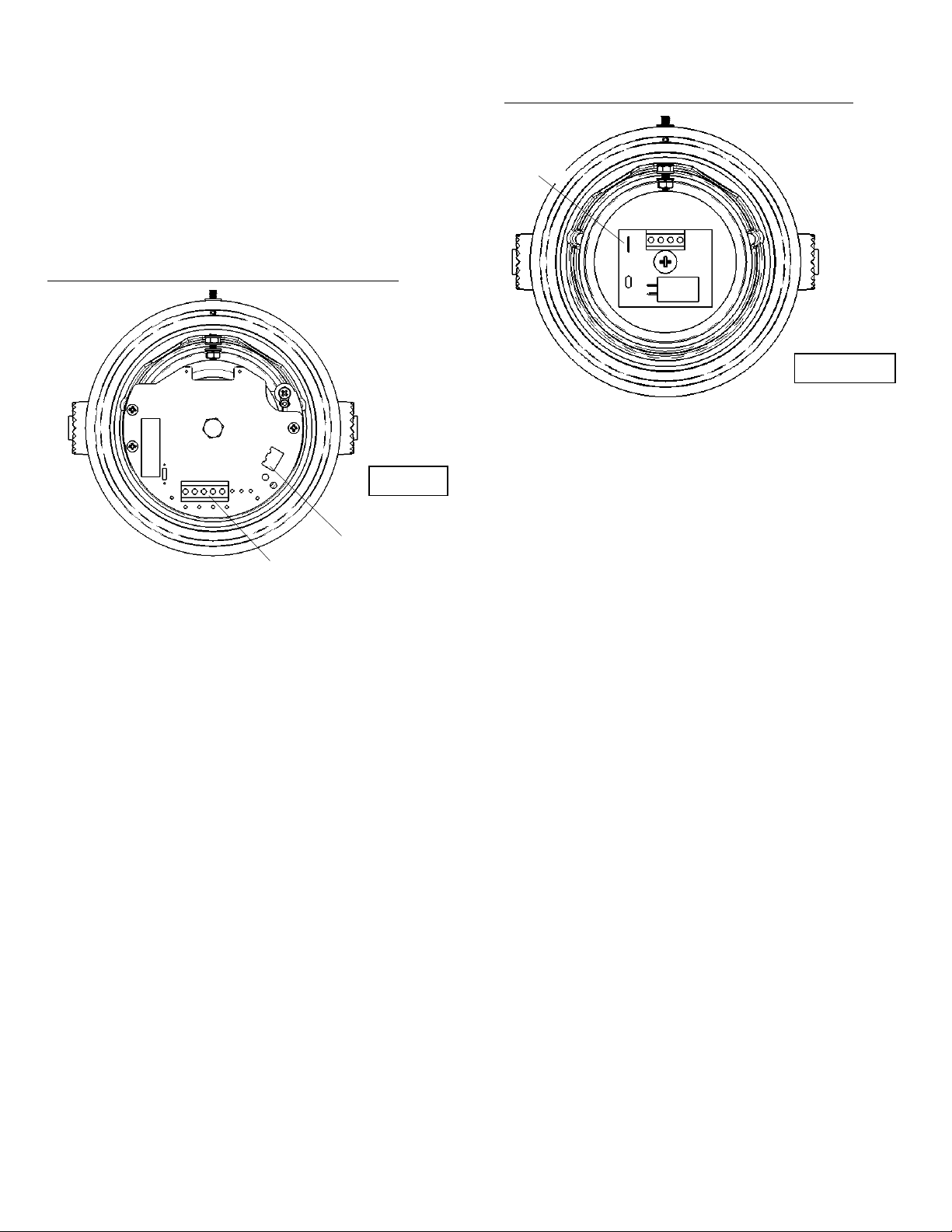
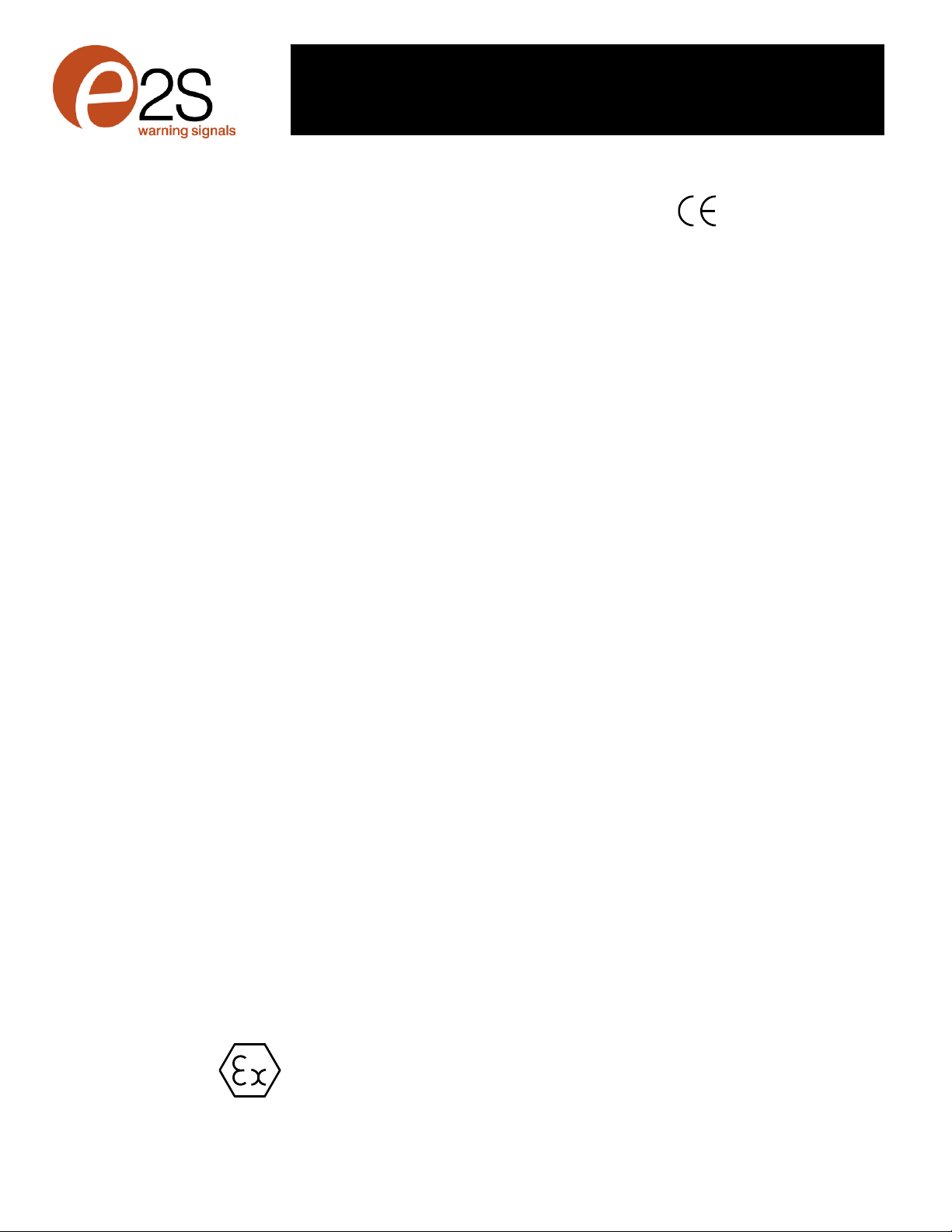
4.2) Specific Conditions
Flameproof joints shall not be repaired or modified in any way
(See figures 1 & 2 for location of flameproof joints).
The enclosure is non-conducting and under certain extreme
conditions may generate an ignition capable level of
2813
II 2G
Epsilon x:
Equipment Group
and Category:
CE Marking:
Notified Body No.

__________________________________________________________________________________________________________________________________
European Safety Systems Ltd. Impress House, Mansell Road, Acton, London W3 7QH [email protected] Tel: +44 (0)208 743 8880
www.e2s.com Fax: +44 (0)208 740 4200
Document No. D157-00-201 Issue 3 25-06-20 Sheet 2 of 4 (2)
electrostatic charge. The user shall ensure that the equipment
is not installed in a location where it may be subjected to
extreme conditions (such as high-pressure steam) which might
cause a build-up of electrostatic charge on non-conducting
surfaces.
4.3) Maintenance, Repair and Overhaul
Maintenance, repair and overhaul of the equipment should
only be carried out by suitable qualified personnel in
accordance with the current relevant standards:
EN60079-19 / IEC60079-19 : Explosive atmospheres -
Equipment repair, overhaul and reclamation
EN 60079-17/ IEC60079-17 : Explosive atmospheres -
Electrical installations inspection and maintenance
WARNING:
Do not open when energised.
Electrostatic charging hazard – clean only with a damp cloth.
Do not open when an explosive atmosphere may be present.
If opening the unit during maintenance operations, a clean
environment must be maintained, and any dust layer removed
prior to opening the unit.
For options on unit repairs or replacement parts, contact E2S
using the contact information in the footer of this installation
manual.
5) Zones, Gas Group, Category and Temperature
Classification
The GNExL2 and GNExL1 sounders have been certified Ex db
IIC T4 , T3 and Ex db IIB T6 , T5 ,T4 dependant on ambient
temperature for full marking see section 2. This means that the
units can be installed in locations with the following conditions:-
Area Classification:
Zone 1 Explosive gas air mixture likely to occur in
normal operation.
Zone 2 Explosive gas air mixture not likely to occur,
and if it does, it will only exist for a short time.
Gas Groupings:
Group IIA Propane
Group IIB Ethylene
Group IIC Hydrogen and Acetylene
Equipment Category: 2G
Temperature Classification:
T1 450o C
T2 300o C
T3 200o C
T4 135o C
T5 100o C
T6 85o C
Ambient Temperature Range:
GNExL1 - For range see Marking Codes Section 2
GNExL2 - For range see Marking Codes Section 2
6) Loudspeaker Location and Mounting
The location of the loudspeakers should be made with due
regard to the area over which the unit must be audible. The
loudspeakers should only be fixed to services that can carry
the weight of the unit.
The loudspeakers should be securely bolted to a suitable
surface using the 7mm diameter boltholes in the stainless steel
U shaped mounting bracket (see figure 1). The angle can then
be adjusted in the direction that the sound is primarily required
to cover. This can be achieved by loosening the two large
bracket screws in the side of the unit, which allow adjustment
in steps of 18°. On completion of the installation the two large
bracket adjustment screws on the side of the unit must be fully
tightened to ensure that the unit cannot move in service.
7) Safety Warning (Electrostatic Hazard)
The acoustic horn section is made of ABS Plastic, therefore to
avoid a possible ELECTROSTACTIC CHARGE the unit must
only be cleaned with a damp cloth.
8) Access to the Flameproof Enclosure
In order to connect the electrical supply cables to the
sounder it is necessary to remove the flameproof cover to
gain access to the flameproof chamber. To achieve by
loosening the M3 Grub Screw within the flameproof cover,
and then unscrew the flameproof cover, taking extreme
care not to damage the flameproof joints in the process.
Figure 1
Flameproof
Chamber Flameproof
Cover
S/S Mounting
Bracket
Plastic Acoustic Horn
Please see Safety Warning
in Section 7 of this manual

__________________________________________________________________________________________________________________________________
European Safety Systems Ltd. Impress House, Mansell Road, Acton, London W3 7QH [email protected] Tel: +44 (0)208 743 8880
www.e2s.com Fax: +44 (0)208 740 4200
Document No. D157-00-201 Issue 3 25-06-20 Sheet 3 of 4 (3)
On completion of the cable wiring installation the flameproof
joints should be inspected to ensure that they are clean and
that they have not been damaged during installation. Also
check that the ‘O’ ring seal is in place. When replacing the
flameproof cover ensure that it is tighten fully with tool
provided.
9) Power Amplifier Selection
It is important that the loudspeakers are connected to power
amplifiers that have outputs that are compatible to the type of
loudspeaker being used. Loudspeakers with a 70V or 100V
line matching transformer fitted must be connected to a power
amplifier with a 70V or 100V line output. Low impedance 8
ohm or 16 ohm loudspeakers must be connected to amplifiers
with a suitable low impedance output. When selecting the
cable size consideration must be given to the current that each
unit draws, the number of loudspeakers on the line and the
length of the cable run.
The following table shows the range of loudspeakers:-
Unit Type Input Wattage Max.
I/P Volts
GNExL2 100V Line 25W 100V
GNExL2 70V line 25W 70V
GNExL2 8 ohm 25W 14.14V
GNExL2 16 ohm 25W 20V
GNExL1 100V Line 15W 100V
GNExL1 70V Line 15W 70V
GNExL1 8 ohm 15W 10.95V
GNExL1 16 ohm 15W 15.49V
The above table also shows the maximum AC signal voltages
at which the loudspeakers can be operated.
The current levels taken by the each loudspeaker will depend
on which output tapping has been selected (see section 13 of
this instruction manual). GNExL2 70V and 100V Line units
have output levels of 25W, 12.5W, 6W and 2W; GNExL1 70V
and 100V Line units have output levels of 15W, 7.5W, 3W and
1W.
10) Cable Selection
When selecting the cable size consideration must be given to
the input current that each unit draws (see table 2 of 4), the
number of loudspeakers on the line and the length of the cable
runs. The cable size selected must have the necessary
capacity to provide the input current to all of the loudspeakers
connected to the line.
SAFETY WARNING: If temperature exceeds 70ºC at entry or
80ºC at branching point use suitably rated cable and cable
glands.
11) Earthing
Both AC and DC loudspeaker units must be connected to a
good quality earth. The units are provided with external
earthing terminals which are both located on the terminal
chamber section of the unit (see figures 2 and 3).
When using the external earth terminal a cable crimp lug must
be used. The cable lug should be located between the two M4
stainless steel flat washers. The M4 stainless steel spring
washer must be fixed between the outer flat washer and the
M4 stainless steel nut to ensure that the cable lug is secured
against loosening and twisting.
12) Cable Glands
The GNExL2 and GNExL1 sounders have dual cable gland
entries which have an M20 x1.5 entry thread as standard. Only
cable glands approved for Ex ‘d’ applications can be used,
which must be suitable for the type of cable being used and
also meet the requirements of the Ex ‘d’ flameproof installation
standards EN 60079-14:2008 / IEC60079-14:2007.
SAFETY WARNING: If temperature exceeds 70ºC at entry or
80ºC at branching point use suitably rated cable and cable
glands.
If a high IP (Ingress Protection) rating is required then a
suitable sealing washer must be fitted under the cable gland.
When only one cable entry is used the other one must be
closed with an Ex ‘d’ flameproof blanking plug, which must be
suitably approved for the installation requirements.
Figure 2
Figure 3

__________________________________________________________________________________________________________________________________
European Safety Systems Ltd. Impress House, Mansell Road, Acton, London W3 7QH [email protected] Tel: +44 (0)208 743 8880
www.e2s.com Fax: +44 (0)208 740 4200
Document No. D157-00-201 Issue 3 25-06-20 Sheet 4 of 4 (4)
13) Cable Connections
The cable connections are made into the terminal blocks on
the pcb assembly located in the flameproof enclosure. See
section 8 of this manual for access to the flameproof
enclosure. The 70V and 100V Line loudspeakers are fitted with
a five way terminal block. Terminal A is common and one of
the other terminals B, C, D or E should be selected depending
on what output level is required (see table below).
Terminals GNExL2 (25W) GNExL1 (15W)
A - B 25W 15W
A - C 12.5W 7.5W
A - D 6W 3W
A - E 2W 1W
A single solid or stranded wire with a cross sectional area of up
to 4mm² can be connected to each terminal way or if an input
and output wire is required two 2.5mm² wires can be
connected to each terminal way. When connecting wires to the
terminals great care should be taken to dress the wire so that
when the cover is inserted into the chamber the wires do not
exert excess pressure on the terminal blocks. This is
particularly important when using cables with large cross
sectional areas such as 2.5mm² and above.
Wire insulation needs to be stripped 6-7mm. Wires may be
fitted securely with crimped ferrules. Terminal screws need to
be tightened down with a tightening torque of 0.56Nm / 5 Lb-in.
The unit will be set as standard to 100V line. But can be easily
altered to 70V line by moving the red selection cable from the
100V line terminal to the 70V line terminal (see figure 4 for
position).
GNExL2 and GNExL1 8 ohm and 16 ohm low impedance
loudspeakers have dual input terminals on the pcb assembly
for input and output wiring. A cable of up to 2.5mm² can be
connected to each terminal. If dc line monitoring is used cut
the link on the board (see figure 5 and section 14 of this
manual).
14) End of Line DC Monitoring
On GNExL2 and GNExL1 loudspeakers, dc line monitoring can
be used if required. Both the 70V and 100V Line units and the
Low Impedance units have blocking capacitors fitted. It should
be noted that each loudspeaker has a 1M ohm bleed resistor
connected across the blocking capacitor and this should be
taken into account when selecting the value of the end of line
monitoring resistance.
The end of line monitoring resistor can be connected across
the terminals on the end of line unit. On the low impedance
units care must be taken with the polarity of the monitoring
voltage.
On 100V and 70V line units the end of line resistor used must
have a minimum resistance value of 4k7 ohms and a minimum
wattage of 2.5 watts
On low impedance units the end of line resistor used must
have a minimum resistance value of 2k ohms and a minimum
wattage of 0.5 watts or a minimum resistance value of 500
ohms and a minimum wattage of 2 watts. On the low
impedance units care must be taken with the polarity of the
monitoring voltage. If an end of line resistor is fitted to a unit
the links on the printed circuit boards of all loudspeakers in the
line must be cut for the dc blocking capacitors to be in circuit in
order to dc monitor the line (see figure 5).
Figure 4
Figure 5
GNExL2 and GNExL1 70V and 100V Line Loudspeakers
GNExL2 and GNExL1 8 ohm and 16 ohm Loudspeakers
- - + +
Link
Power Setting
Terminals A - E
70/100V Line
Setting Terminal
This manual suits for next models
1
Other E2S Speakers manuals

E2S
E2S D1xL1 Series User manual

E2S
E2S STExL1R008 User manual

E2S
E2S BExL15D User manual

E2S
E2S D2xL1 Series User manual

E2S
E2S BExL25E User manual

E2S
E2S E2xL25UL Troubleshooting guide

E2S
E2S STExL1 Series User manual

E2S
E2S BExCL15-05D User manual

E2S
E2S GNE L2 Series User manual

E2S
E2S E2xL15UL User manual