EAS Electric EINSOLAR5V User manual

Guía rápida de instalación
3. Instalación
Requisitos de instalación
1. Instale el inversor donde no pueda tocarse
por descuido.
2. Instale el inversor en superficies sólidas y lisas.
3. El inversor no debe instalarse cerca de objetos
inflamables o explosivos.
Instalación del cable PE
Hay un segundo terminal PE en la parte inferior del inversor.
Compruebe que el terminal PE está adecuadamente
conectado a tierra y que la resistencia de tierra es inferior a 10
Ohm.
3.2
Nº Descripción
1 Carcasa
2 Terminal M5 con conductor protector
3 Tornillo de cabeza plana M5×13
Fíjelo firmemente a la carcasa (destornillador T25, par de apriete: 2.5Nm).
AVISO
Es imprescindible conectar adecuadamente a tierra el segundo terminal PE y el terminal CA. Si no
se conectan ambos PE la garantía quedará invalidada.
Accesorios incluidos
Inversor Placa de
montaje
Accesorios
de montaje Conector CA Conector Wi-Fi
(opcional) Documentos
1 1 1 2 1 1 1
2.
Luz solar
directa
Exposición a
la lluvia
Acumulación
de nieve
EVITE
Instalación
׃خׁ
1
2
3
1. Display
2. Interruptor CC
(opcional)
3. Terminales fotov.(s)
4. Conector Wi-Fi/GPRS
(opcional)
5. Conector para
contador/DRM
6. Terminal CA
7. Segundo terminal de
protección
Modelos: EINSOLAR5V, EINSOLAR6.5V
1. Partes del producto An
Al Fo
12 3 4 5 6 7
ׁ׀ǿǿـׂΧف
Profund.ׇ׀ǿǿ
ׁ׆׀ǿǿ
1. Use la placa de montaje como plantilla para taladrar orificios de 10mm de diámetro y 70mm de profundidad.
2. Fije la placa de montaje con los tornillos y los pernos de expansión incluidos en los accesorios de montaje.
3. Monte el inversor en la placa de montaje.
4. Compruebe ambos lados del disipador de calor y asegúrese de que el inversor está instalado de forma estable.
5. Use tornillos M5 (con un destornillador T25 y un par de apriete de 2.5Nm) para unir las aletas del disipador de calor
a la placa de montaje.
6. Es recomendable incorporar un dispositivo de bloqueo antirrobo al inversor.
Pasoׄ Pasoׅ Paso׆
ׁ׆׀ǿǿ
Orificios montaje
Dimensiones: An×Al×Fo=395 x 328 x 154mm
Enchufes CC
MC4 o D4
(opcional)
Especificaciones del cable
Nº Item Tipo Especificaciones
1 Cable PE de
protección
Cable de cobre para
exteriores de un núcleo Sección transversal del conductor:6mm2
2 Cable
salida CA
Cable para exteriores de
cobre
Sección transversal:4-6mm2
Diámetro externo:9-14mm
3 Cable de
entrada CC
Cable FV estándar para
exteriores, recomendado
modelo PV1-F
Sección transversal del conductor:
2.5-6mm2
Diámetro externo: 4.5-7.8mm
4 Medidor Cable para exteriores de par
trenzado de dos núcleos
apantallado
Sección transversal del conductor:
0.14-1.5mm2
Diámetro externo:aprox 9mm
5 DRED CAT-5E, cable apantallado para
exteriores
Estándar para EIA/TIA 568B
Diámetro externo: aprox. 9mm
Longitud máxima del cable: 1000m
Paso 1 Paso2Paso3

3.2 Montaje y conexión de los cables de CA
Peligro mortal debido a la alta tensión en el inversor
Antes de conectar ningún cable o componente eléctrico, compruebe que el interruptor CC y el
disyuntor de CA están APAGADOS y no pueden reactivarse por accidente.
PELIGRO
Conexión y montaje de los cables de CC
Es obligatorio cumplir los siguientes requisitos o la garantía quedará invalidada.
3.3.1 La tensión abierta máxima de cada string es inferior a 600V.
3.3.2 La corriente máxima de cortocircuito de cada entrada fotovoltaica es inferior al límite permitido
del inversor.
3.3.3 Cada string tiene buen aislamiento a tierra en todos los casos.
3.3.4 Compruebe que los conectores de CC tienen la polaridad correcta.
3.3.5 Si los conectores fotovoltaicos no están bien montados y asegurados, puede darse un arco o
sobrecalentamiento.
3.3
Conexión Wi-Fi/GPRS (Opcional)
El dispositivo WiFi puede incluirse con el aparato de forma opcional.
3.4.1 Conecte adecuadamente el dispositivo en el terminal COM1.
3.4.2 Consulte las instrucciones para la conexión y configuración del Wi-Fi en su manual
correspondiente.
3.4
Nota: Asegúrese de que el conector está correctamente instalado.
Introduzca el conductor en un
casquillo adecuado según DIN
46228-4 y crimpe
Conecte los conductores crimpados L, N
y PE en los terminales correspondientes
y apriete los tornillos (par de apriete
1.4N·m)
Ensamble la tapa de
cierre, el casquillo
roscado y la tuerca
giratoria
Enrosque el conector
CA con firmeza en la
toma
Paso 1 Paso 2 Paso 3
4. Puesta en marcha
Compruebe que:
1. El inversor y la placa de montaje se han instalado correctamente.
2. Las partes metálicas expuestas del inversor están conectadas a tierra.
3. La resistencia entre los sistemas fotovoltaicos y la tierra es superior a 1Mohm.
4. En los terminales CC que no se usen, hay conectores CC sellados con tapones resistentes al agua.
5. La tensión de red en el punto de conexión del inversor está dentro del rango permitido.
6. El disyuntor de CA debe ser adecuado y estar correctamente conectado.
7. Los conectores de los cables de comunicación deben estar correctamente conectados y apretados.
Encendido
Encienda el interruptor de CC tras realizar las comprobaciones arriba indicadas, y encienda el
disyuntor de CA. Cuando haya suficiente potencia de CC aplicada y se cumplan las condiciones de
la red, el inversor se pondrá en marcha automáticamente.
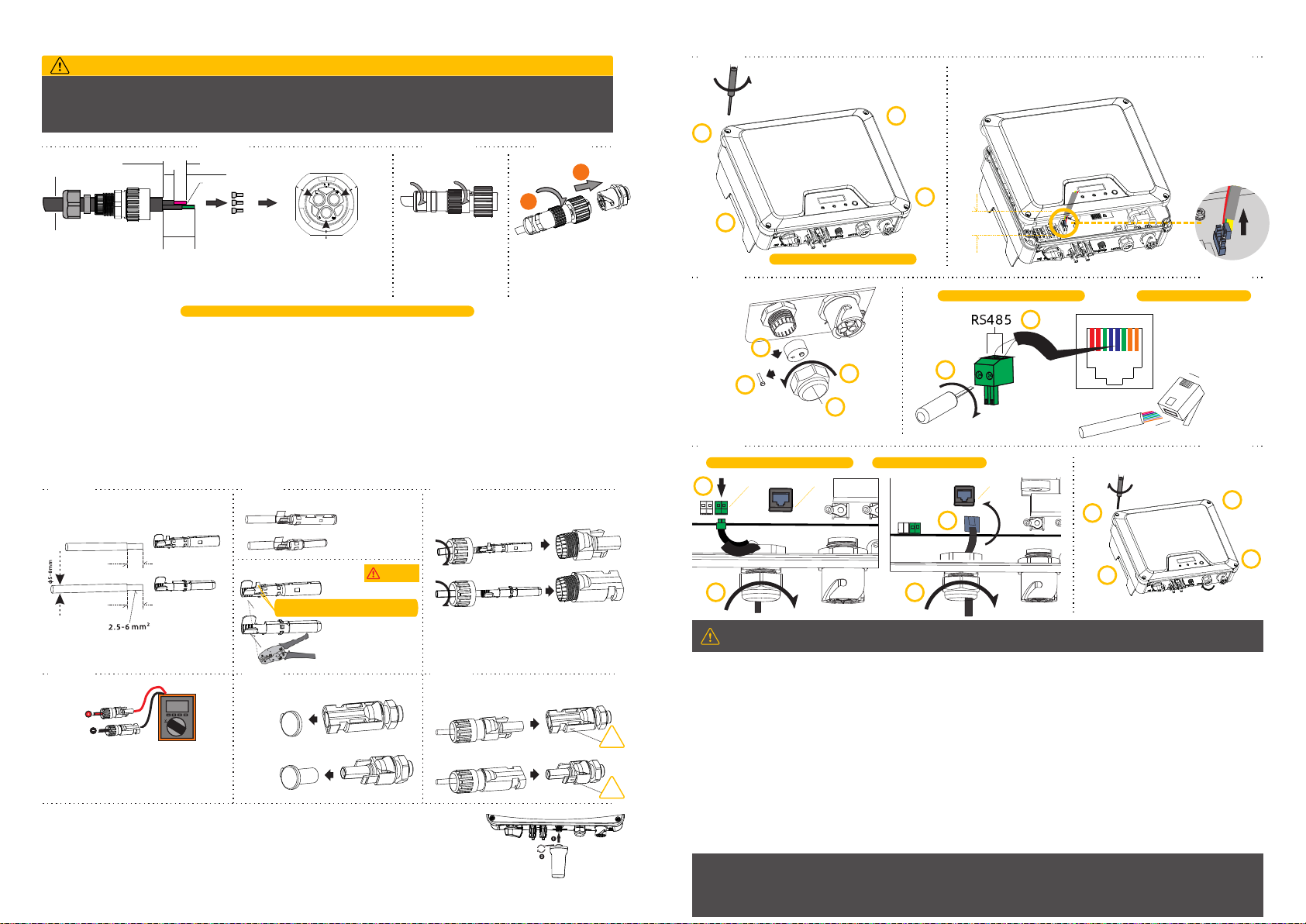
3.5 Contador Inteligente y Conexión DRED
AVISO
DRED
Pin1: DRM1/5
Pin2: DRM2/6
Pin3: DRM3/7
Pin4: DRM4/8
Pin5: RefGen
Pin6: Com/DRM0
Pin7: N/A
Pin8: N/A
1 2345678
Conector Rj45
1 8
Conector Rj45
B
A
Paso 1 Paso 2
Paso 3 Paso 4
Paso 5 Paso 6
Use un destornillador (Tx25, par de
apriete: 2.5 N·m) para aflojar los tornillos
de la carcasa siguiendo el orden
indicado (1~4)
1
2
3
4
Deje los tornillos en los agujeros
Levante la carcasa con cuidado unos 80mm y desconéctela
de la placa.
Aprox.
80mm
1
2
3
4
Desenros-
que la
tuerca
Retire los
tapones
Retire uno de los tapones y
deje el resto en su sitio para
evitar que entre humedad
Pase el
cable
Tipo destornillador: Plano 0.4 x 2.5
1
2
Para conexión del Smart Meter
METER DRED
o Conexión del terminal DRED
1
2
1
2
Apriete los tornillos de la carcasa siguiendo
el orden indicado (1~4).
Fije el prensaestopas con firmeza, con un par
de apriete de 2.5 a 3N·m para apretar la tuerca.
(Tx25, par de apriete:
2.5 N·m)
1
2
3
4
φ9-14 mm
Aprox. 45 mm
Aprox. 10 mm
Para “L” y “N”
Para “PE”
Aprox. 50mm
4....6mm²
PE
LN
Comunicación Smart Meter Cableado DRED
o
1
2
Paso 4Paso 5 Paso 6
clic
clic
7mm
7mm
PV1-F/UL-ZKLA/USE2
PV1-F/UL-ZKLA/USE2
Monte los conectores
2.6-2.9 N·m
Positivo
Negativo
Monte los extremos del cable D4
Terminal positivo
Terminal negativo
Alicates de crimpar
Nota: No crimpe esta parte
Paso 2
Monte los extremos del cable MC4
Terminal positivo
Terminal negativo
Paso 1 Paso 3
Retire el aislamiento
AVISO
Compruebe si los cables están bien
instalados tirando hacia fuera
Compruebe la polaridad de los strings
FV
Compruebe que la tensión de circuito
abierto es inferior al límite de entrada
del inversor 600V
Retire los tapones sellantes
de los terminales FV
Si hay un terminal que no se
vaya a usar, séllelo con un
tapón.
Introduzca los conectores en el
terminal hasta que oiga un clic.
Para AS/NZS 4777, son válidos: DRM0, DRM5, DRM6, DRM7 y DRM8. Asegúrese de volver a
montar la carcasa y los casquillos correctamente.
Para más información, consulte el manual de usuario y otros documentos en www.easelectric.es
EAS ELECTRIC SMART TECHNOLOGY, S.L.
P.I. Codonyers, C/Principal, 4 46220 Picassent (Valencia, SPAIN)

Quick Installation Guide
Models: EINSOLAR5V, EINSOLAR6.5V
3. Installing
Installation Requirements
1. Please install the inverter(s) in places that can avoid
inadvertent contact.
2. Please install the inverter on solid/smooth surfaces.
3. The inverter(s) should not be installed near inflammable or
explosive objects.
Installing the PE Cable
A second PE terminal is equipped at the bottom of the inverter.
Ensure the PE terminal is reliably grounded and the grounding resistance is
less than 10 Ohm.
3.2
Object Description
1 Housing
2 M5 terminal lug with protective conductor
3 M5×13 pan head screw
Tighten it firmly into the housing (T25 screwdriver, torque: 2.5Nm).
NOTICE
Proper grounding connection of the second PE terminal and the AC terminal is mandatory. NOT properly connecting
both PE will void all product warranty.
Packing List
Inverter Mounting
Bracket
Mounting
Accessories AC Connector Wi-Fi stick
(optional) Documents
1 1 1 2 1 1 1
2.
Direct
Sunlight
Rain
Exposure
Snow
Lay up
AVOID
No Item Type Specifications
1 PE cable Single-core outdoor copper cable • Conductor cross-section: 4-6 mm²
2 AC Output
cable
Outdoor copper cable • Conductor cross-section: 4-6 mm²
• Cable outer diameter: 9-14 mm
3 DC Input
cable
Standard outdoor PV cable,
PV1-F Model recommended • Conductor cross-section: 2.5-6 mm²
• Cable outer diameter: 5-8 mm
4 Meter Two-core outdoor shielded
twisted pair cable • Conductor cross-section: 0.14-1.5 mm²
• Cable outer diameter: approx. 9 mm
5 DRED CAT-5E, outdoor shielded cable
Standard for EIA/TIA 568B
• Cable outer diameter: approx. 9 mm
• cable maximum length 1000m
Cable Specifications
Mounting
3.1.1 Use the mounting bracket as a template mark and drill holes of 10mm diameter and 70mm depth
3.1.2 Fix the mounting bracket with the screws and expansion bolts packed in mounting accessories
3.1.3 Attach the inverter to the mounting bracket
3.1.4 Check both sides of heat sink and ensure the inverter is stably attached
3.1.5 Use M5 screw (with T25 screwdriver, torque: 2.5Nm) to attach the heat sink fins to the mounting bracket
3.1.6 It is recommended to attach an anti-theft lock to the inverter
3.1
1
2
3
1. LCD&LED or LED
2. DC switch (optional)
3. PV Terminal (s)
4. Wi-Fi/GPRS Stick(optional)
5. Cable gland for Meter/DRM
6. AC Terminal
7. Second PE Terminal
Product Overview
1. W
H
D
12 3 4 5 6 7
10mm(2 )Χ
Deep 70mm
160mm
Step 1 Step 2 Step 3
Step 4 Step 5 Step 6
160mm
Standby holes
Dimension:W×H×D=395 x 328 x 154mm
DC Plugs
MC4 or D4
(optional)

3.2 AC Wire Assembly and Connection
Danger to Life due to High Voltages in the Inverter
Before connecting any electrical wires and components, please ensure the DC switch & AC circuit breaker are switched
OFF and cannot be reactivated.
DANGER
DC Wire Assembly and Connection
Meeting the following requirements is mandatory. All warranty rights will otherwise be invalid.
3.3.1 Maximum open voltage of each string is less than 600V.
3.3.2 Maximum short circuit current of each PV input is less than inverter allowable limit.
3.3.3 The string is well insulated to ground in all cases.
3.3.4 Make sure that the DC connectors have the correct polarity.
3.3.5 If the PV connectors are not assembled properly and locked into place, arc or overheat may be induced.
3.3
Wi-Fi/GPRS Connection (Optional)
The stick is included in the scope of delivery as an option.
3.4.1 Tighten the stick into the COM1 port. Make sure the stick is securely connected.
3.4.2 For the connection and configuration of the Wi-Fi stick please refer to <Wi-Fi stick User manual> .
3.4
Note: Please insure that the connector has been correctly installed!
Insert the conductor into a suitable
ferrule acc. to DIN 46228-4 and crimp
Insert the crimped conductors L, N and PE
into corresponding terminals and tighten the
screws (torque 1.4N·m)
Assemble the locking cap,
threaded sleeve and swivel
nut together
Screw the AC connector
firmly into the socket
Step 1 Step 2 Step 3
Please check if
1. The inverter and mounting bracket have been correctly installed. 2. The inverter’s exposed metal surface has a ground
connection. 3. The resistance between PV arrays and ground is greater than 1Mohm. 4. For any unused DC terminals,
there are DC connectors inserted to the terminal and sealed with waterproof caps. 5. The grid voltage at the point of
connection of the inverter is within the permitted range. 6. The AC circuit breaker must be correctly rated and wired. 7.
The cable communication connectors have been correctly wired and tightened.
Startup
Switch on the DC switch after finishing the above checks, then switch on the AC circuit breaker. When there is sufficient DC
power applied and the grid conditions are met, the inverter will start to operate automatically.
Commissioning
4.
Smart Meter and DRED Connection
3.5
NOTICE
For AS/NZS 4777, DRM0, DRM5, DRM6, DRM7, DRM8 are supported.
Make sure the cover and the communication cable gland has been mounted properly and adequately
DREDDREDMETER
Pin1:DRM1/5
Pin2:DRM2/6
Pin3:DRM3/7
Pin4:DRM4/8
Pin5:RefGen
Pin6:Com/DRM0
Pin7:N/A
Pin8:N/A
12345678
Rj45 Plug
1 8
Rj45 Plug
B
A
Step 1 Step 2
Step 3 Step 4
Step 5 Step 6
Use a screwdriver (Tx25, torque:2.5 N·m) to
loosen the screws of the cover following the
indicated sequence (1~4)
1
2
3
4
Please leave the screws on the holes
Carefully lift the cover for a vertical distance of approx. 80mm and
disconnect from power board
Approx.
80mm
1
2
3
4
Unscrew
the nut
Take the
sealing out
Remove one of the filler-plug
and keep the remaining in its
slot to prevent moisture from
enter
Route
the cable
Screwdriver Type: Blade 0.4 x 2.5
1
2
or
For smart meter connection DRED terminal connection
1
2
1
2
Tighten the screws on the cover following
the indicated sequence (1~4).
Firmly secure cable gland by using a torque
of 2.5 to 3N·m to tighten the swivel nut
(Tx25, torque:2.5 N·m)
1
2
3
4
φ9-14 mm
Approx. 45 mm
Approx. 10 mm
For “L” and “N”
For “PE”
Approx. 50mm
4....6mm²
PE
LN
Smart meter communication assembly DRED cable assembly
or
1
2
Step 1 Step 2 Step 3
Step 4 Step 5 Step 6
click
click
6
7mm
7mm
PV1-F/UL-ZKL A/USE2
PV1-F/UL -Z KL A/USE2
Assemble the connectors
2.6-2.9 N·m
Positive
Negative
Assemble the cable endsD4
Positive terminal
Negative terminal
Crimp pliers to cable ends
Note: Don't crimp this part!
Assemble the cable endsMC4
Positive terminal
Negative terminal
www.easelectric.es
EAS ELECTRIC SMART TECHNOLOGY, S.L.
Address: P.I. Codonyers, C/Principal, 4 46220 Picassent (Valencia, SPAIN)
This manual suits for next models
1
Table of contents
Languages:
Other EAS Electric Inverter manuals
Popular Inverter manuals by other brands

Generac Power Systems
Generac Power Systems Guardian 004992-2 owner's manual

Westerbeke
Westerbeke 29.0 EGED 60Hz Operator's manual

Steamist
Steamist TSG-12 installation instructions

Schumacher
Schumacher PID-750 owner's manual

GSL
GSL INV600-12 operating instructions

Wegner
Wegner Crane CFW500 series Applications manual