4Eastwood Technical Assistance: 800.544.5118 >> techelp@eastwood.com To order parts and supplies: 800.345.1178 >> eastwood.com 5
CREATING ARC SHAPES IN SHEET METAL
The Eastwood Slip Roll is a great metal working tool that will expand your metal working
possibilities. Before making an actual piece for your project, acquire additional pieces of the
same size and thickness to practice on and to dial in the desired radius. It is not possible to
preset the Slip Roll to a pre determined radius so it will require some trial and error to get
the correct radius. The more often you use the Slip Roll, the more familiar you will get with
the adjustments to make a specific radius.
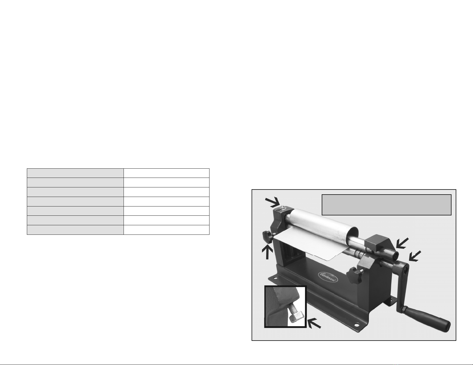
1. Turn the Thickness Adjustment Knobs
(A) and assure that the top and bottom
rollers are parallel.
2. Adjust the Rear Roller Knobs (B) so
that the roller is all the way down.
3. Place the piece of sheet metal you will
be bending between the top and bottom
front rollers and tighten the Thickness
Adjustment Knobs (A) until it is pinching the piece of sheet metal. Make sure when making this
adjustment that both sides of the roller are tightened the same amount so that the same amount
of pressure is being exerted across the entire length of the piece and the rollers are parallel.
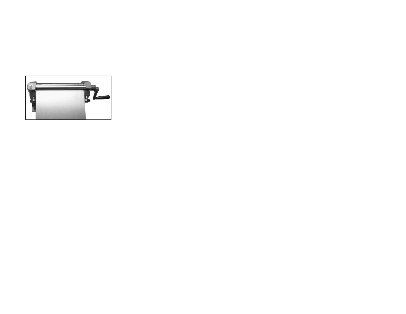
4. Rotate the Hand Crank (D) clockwise (away from you) to begin feeding the piece into the rollers
until the piece is directly above the rear roller.
5. Adjust the Rear Roller Knobs (B) to set the radius of the piece. The more this roller is raised, the
smaller the radius of the part will be. Be sure to adjust the knobs equally on both sides to avoid
making a conical shape.
6. Rotate the Hand Crank (D) clockwise (away from you) to form the piece. Continue rotating the
hand crank until the entire pieces exits the rollers.
CREATING CYLINDERS IN SHEET METAL
The Eastwood Slip Roll can not only create bends but can also be used to form cylinders.
1. Determine the diameter of the cylinder you want to form and calculate the circumference by
using the formula below:
Circumference = 3.14 X Diameter
2. The circumference is the length of your piece. With a determined length you can cut your
piece to size.
3. Turn the Thickness Adjustment Knobs (A)and assure that the top and bottom rolls are parallel.
4. Adjust the Rear Roller Knobs (B) so that the roll is all the way down.
5. Place the piece of sheet metal you will be bending between the top and bottom front rolls and
tighten the Thickness Adjustment Knob (A) until it is pinching the piece of sheet metal. Make
sure when making this adjustment that both sides of the roll are tightened the same amount so
that the same amount of pressure is being exerted across the entire length of the piece.
6. Rotate the Hand Crank (D) clockwise (away from you) to begin feeding the piece into the rolls
until the piece is near half way over the rear roll.
7. Adjust the Rear Roll Knobs (B) to set the diameter of the piece. The more this roll is raised, the
smaller the diameter of the part will be. Be sure to adjust the knobs equally on both sides to
avoid making a conical shape. It is better to make the initial forming too large of a diameter rather
than too small as a diameter that is formed too large can be reformed to a smaller diameter. If
the diameter is made too small initially, it cannot be reformed and must be scraped.
8. Rotate the Hand Crank (D) until the entire piece has passed over the rolls. At this point you will
have formed a half of a cylinder.
9. Remove the piece from the slip roll and rotate the piece around to form the opposite end of
the piece.
10. Rotate the Hand Crank (D) until the entire piece has passed over the rolls. At the point you will
have formed a complete cylinder. If the piece is not a complete cylinder and the ends do not
touch, raise the rear roll slightly at both ends equally and rotate the Hand Crank (D) until the
entire piece has been rolled again. Continue making tightening adjustments to the rear roll if
necessary to get the ends of the cylinder to come together to form a complete cylinder.
Once the cylinder has been formed, you will need to remove it from the top
following the below instructions:
1. Loosen both Thickness Adjustment Knobs (A) equally.
2. Slide the Top Roller Release (C) mount away from the slip roll to remove it from the base.
3. Lift the top roll out of the base on an angle but do not try and remove the roll. Simply slide the
work piece off the top roll.
4. Replace the top roller back into the base and reinstall the Top Roller Release (C).