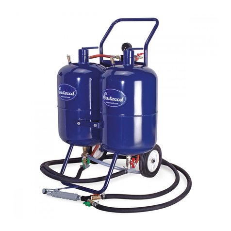
Eastwood 2-PS User manual

THE EASTWOOD COMPANY
HEAVY DUTY PORTABLE SODA
BLASTER
OPERATOR’S BOOKLET

Model 2-PS Quick Set Up Guide
1. Connect the Model 2-PS to your compressor, using an air supply line of at least ½” I.D (Internal
Diameter). If you are using an air supply line longer than 30 ft., or with an air compressor
greater than 30 cfm, use a ¾” I.D. air supply line with a reducer to thread into the ½” NPT
(National Pipe Thread) air inlet valve on the front of the Model 2-PS.
2. DO NOT USE a plug in male/female type quick disconnect on your air supply line. If you are
going to use a quick disconnect, use a “Chicago Style” quick disconnect. If you are not sure
what this is, just Google search for “Chicago Style Coupling”.
3. Load the Model 2-PS with soda blast media. ALWAYS make sure that the air inlet valve (where
your air supply line goes into the Model 2-PS) is in the closed/off position, and that the tank is
fully depressurized before attempting to load with soda blast media. You depressurize the
tank using the valve on the top of the tank. You can then unscrew the large nut on top of the
tank and place in your funnel. The Model 2-PS tank will hold up to 100# of soda blast media.
Make sure that you pour the soda blast media thru a screen before loading. This will catch any
clumps and help prevent clogging. After loading, replace/tighten nut and close the
depressurizing valve.
4. Make sure that the ball valve on the bottom of the tank is in the fully open position.
5. Turn on your air compressor and set the compressor to 120 psi (pounds per square inch).
6. Open the air inlet valve on your Model 2-PS (where your air supply line goes into the Model 2-
PS).
7. Set your final blasting pressure on the Model 2-PS adjustable pressure regulator by gently
pulling up on the black knob (You should hear a slight click). There are arrows on top of the
knob indicating which way to turn to increase or decrease the pressure. Watch the pressure
gauge on the Model 2-PS and turn the knob to adjust the pressure. When the gauge reaches
the pressure you want, push the knob back down. You should hear a slight click.
8. Set the Model 2-PS adjustable pressure regulator within the 80 –100 psi range to remove paint
from hard surfaces like metal or stone. If you are blasting on soft materials like wood or
fiberglass always start at a very low final blasting pressure like 30 or 40 psi and slowly increase
the pressure until you find the best pressure that cleans and doesn’t harm the soft surface.
9. Always wear a respirator and eye protection when soda blasting. The Model 2-PS comes with
a bump cap and blasting hood. If you do not use the hood, make sure you wear full goggles to
protect your eyes.
10. To blast, just depress the handle at the end of the blast hose and blast at approximately 45
degree angle to the surface.
11. When you complete your work for the day, turn off the air compressor, close the air inlet valve
on the Model 2-PS, and depressurize the tank. Empty any soda from the tank if you are not
going to use the Model 2-PS again for any length of time more than a week or two. To empty
tank, loosen the pipe union between the ball valve on the bottom of the tank and the control
box. This will remove the control box. After soda is drained out, replace control box and
carefully tighten the pipe union.

Model 2-PS Quick Trouble Shooting Guide
In the event that you encounter an issue with your Model 2-PS, listed below are
some quick solutions to get you up and running again.
1. Make sure that you have enough soda blast media in the tank. When the
media level gets too low, you may encounter erratic soda spray. Add more
soda blast media. Always make sure that you pour your soda blast media
through a screen before putting into the machine. This will catch any clumps
that sometimes occur even in new unopened bags of media.
2. Make sure the ball valve on the bottom of the tank is fully open.
3. If you get air coming out of the nozzle, but no soda, normally it means that you
have a clog or that the control box tubes need to be replaced. Check to see if
your restrictor, or the manifold that your blast hose connects to, is clogged. If
so, clean it out. Inspect the control box tubes to make sure they do not have a
hole/tear in them. If one of the tubes has failed, replace with the proper
control box tubes. DO NOT use any other type of tube. The tubes are a special
rubber composition for maximum tube life and machine performance.
4. If you are getting a lot of water in the bowl of the adjustable pressure
regulator, you are probably getting water in the tank. Moisture is the main
cause of clogging in any soda blaster. Attach a water filter to the air inlet of
the Model 2-PS to catch any excessive moisture that is being pumped by the air
compressor.
5. When replacing control box tubes, ALWAYS make sure that the ends of the two
adjustment bolts are EXACTLY 1” from the face of the metal plate they go
through. This measurement is critical for proper operation of the machine.
6. Check the entire length of the small diameter red and black tubing that attach
to the trigger mechanism for kinks or holes. Replace if necessary.
7. Make sure the plunger on the handle trigger mechanism is operating properly.
When the plunger is not pushed down, the hole in the plunger should be fully
visible.

SODA BLASTING
PERFORMANCE TIPS
•We have been finding soda “clumps” in new bags of soda blast media from
the factory. These clumps will clog the restrictor in the Model 2-PS and 2-S,
and the down tubes in the Performance Plus. We recommend that you
screen your soda through a piece of 1/16” mesh into a bucket, and then fill
your soda blaster. This will save you time in the long run, and also increase
the life of the tubes inside of your control box on the Model 2-PS and 2-S.
•Never leave unused soda blast media in your soda blaster overnight. Always
empty any unused media into a sealed plastic container between uses. Also,
put partially used bags of soda blast media into a plastic garbage or lawn bag
and seal the bag. Moisture from the air can otherwise be absorbed by the
media and can cause clogging problems in restrictors and tubes.
•The moisture trap is not a moisture filter. If you see an accumulation of
water in the trap, chances are the moisture is also getting into the tank and
being absorbed by the soda blast media, potentially causing clogging. If you
are in a high humidity environment, you may need an in-line moisture filter.
We are currently testing several brands to determine which one works best
with our units. In extreme conditions, an air chiller may be necessary.
•Always keep the soda blast delivery hose as straight as possible while using
our portable soda blasters. Do not operate your unit with the hose coiled or
with sharp radius curves. The soda blast media will wear away the hose
from the inside causing premature hose failure. The media stream will also
lose cleaning power from “bouncing” around the bends.
•Never use a quick disconnect coupling with your soda blaster. The small
inside diameter of such couplings will restrict the airflow from your
compressor, and will adversely affect the performance of your unit. Such
connections can also be potential safety hazards.
•Always use a minimum 3/8” inside diameter air delivery hose from your
compressor to the Model 2-PS and 2-S Soda Blasters. If you use one of the
larger nozzles (3/8” or 1/4"), you must use a 1/2" I.D. hose.
•2-PS users should follow the nozzle size recommendations found on the
“Estimated CFM Requirements” chart. Improper nozzle size and air
delivery hose I.D. in relation to your air compressor’s delivered CFM will
drastically affect the performance of your unit.
•Performance Plus users should make sure not to overfill the unit with soda
blast media. The top hole on the pickup tube must be above the media level
to avoid clogging.

SODA BLASTER
MODEL 2-PS HD PORTABLE SODA BLASTER
ESTIMATED CFM REQUIREMENTS
PSI
90
13
19
29
+36
+50
80
12
18
27
34
+45
60
10
15
23
30
35
40
7
10
18
23
32
3/32” 1/8” 5/32” 3/16” ¼”
ESTIMATED MEDIA USAGE (LBS / MINUTE)
PSI 1/8” RESTRICTOR
90
.51
.92
1.47
2.21
4.04
80
.46
.88
1.38
1.70
3.25
60
.37
.78
1.20
1.57
2.62
40
.28
.55
.97
1.34
2.52
3/32” 1/8” 5/32” 3/16” ¼”
PSI 7/64” RESTRICTOR
90
.32
.58
.93
1.39
2.98
80
.29
.55
.92
1.33
2.40
60
.27
.53
.90
1.26
1.94
40
.26
.50
.88
1.21
1.86
3/32” 1/8” 5/32” 3/16” ¼”
PSI 3/32” RESTRICTOR
90
.29
.53
.84
1.26
2.24
80
.26
.50
.82
1.21
1.80
60
.25
.47
.80
1.12
1.45
40
.23
.45
.79
1.09
1.25
3/32” 1/8” 5/32” 3/16” ¼”
NOTES:
•FIGURES USED ARE BASED ON OUR TEST DATA. ACTUAL RESULTS
WILL VARY.
•CFM REQUIREMENTS BASED ON “DELIVERED CFM” TO UNIT.
•LBS / MINUTES MEDIA USAGE BASED ON MAINTENANCE GRADE
SODA SPRAYED INTO FREE AIR.
•½” ID AIR SUPPLY LINE USED.

TABLE OF CONTENTS
Section 1.0 Introduction
1.1 Soda Dry Blast Media
Section 2.0 The Heavy Duty Portable Dry Soda Blaster Model 2-PS
2.1 Features and Benefits
2.2 Site Requirements
2.3 Specifications
Section 3.0 Assembly
3.1 Start-Up Instructions
Section 4.0 Operating Procedures
4.1 Safe Use Instructions
4.2 Loading Soda Blast Media
4.3 Operation
Section 5.0 Maintenance and Troubleshooting Guide
5.1 Blast Nozzle Replacement
5.2 Water Spray Nozzle Replacement
5.3 Restrictor Replacement
5.4 Troubleshooting Guide
Section 6.0 Servicing the Soda Blast Unit
6.1 Servicing the Model 2-PS
6.2 Service and Adjustment of the Control Unit
6.3 Replacement Parts

1.0 Introduction
This manual will provide you with important information about the Heavy Duty
Portable Dry Soda Blaster Model 2-PS and its safe use.
The Model 2-PS is an abrasive blasting system that converts compressed air and dry
soda abrasive media particles into an effective cleaning process. The soda blaster
unit is a simple design and user-friendly, taking advantage of the unique capabilities
of soda blast media shot through a blast nozzle to perform cleaning. It is to be used
for the removal of various soils and residue from a variety of parts and surfaces.
Read this entire booklet carefully before you use the Model 2-PS. Keep this booklet,
along with the material safety data sheet you should receive with your soda blast
media. It is important that you follow all safe-use instructions carefully, as well as
all the directions and procedures provided in this manual, and on the machine
labels.
1.1 Soda Dry Blast Media
Information about the soda blast material to be used in this machine should be
included on the material data safety sheet provided by the supplier of the product.
Read the MSDS carefully. Follow all Safe-Use Instructions and other directions and
procedures provided in the MSDS.
2.0 The Heavy Duty Portable Dry Soda Blaster Model 2-PS
The Model 2-PS is a pressure driven abrasive blast system that is used in manual
cleaning operations. By using dry soda media, the Model 2-PS is a versatile system
that can be used for numerous cleaning activities. The operator has precise control
of the abrasive flow rate and velocity for efficient operation. The Model 2-PS is a
fully portable system that includes bump hat and operator hood to protect the
operator from dust and other contaminants. Air safety lock out, ceramic nozzle
assembly, and water nozzle for spray off and dust reduction, provide the operator
with clear vision of the abrasive cleaning process.
The unit incorporates as ASME rated pressure vessel that contains the Soda Blast
Media, and a Control Unit designed to regulate the flow of compressed air and
media to the nozzle.

2.1 Features and Benefits
Standard Features include:
•ASME Code Tank-Certified Quality
•100 Lb. Blast Media Capacity
•25 Ft. of Heavy Duty ½” I.D. Abrasive Resistant Hose
•New Control Valve System to Efficiently Regulate the Flow of Compressed
Air and Media to the Nozzle
Value Added Features include:
•Water Feed Line with Rinse Off Capability for Dust Control
•Rugged Heavy Duty Steel Frame with Wheels for Easy Mobility
•Interchangeable Nozzle Holder (Ceramic Nozzle Standard)
•Optional blast nozzles and control restrictor combinations available for
operational flexibility
•Pressure Regulator and Air Line Moisture Filter with Gauge- Better Control
of Finish
•Tall Vertical Tank Design-Better Media Flow
•Remote Blast Control
- Automatic Shut-off if Handle Pressure is Released
- Control at Nozzle Handle
- System Shuts Off at the Tank
•Blast Hood with Bump Cap (included)-Added Safety Protection for the
Operator
•Contains Features Usually Available Only on More Expensive Models
2.2 Site Requirements
Several factors are considered essential when determining an acceptable work site
environment for the Model 2-PS. These requirements include:
•The work site should be as smooth and level, as possible, to allow easy
movement and adjustment of the equipment.
•The work site must be well ventilated.
•The work site should have sufficient lighting.
•The Model 2-PS should not be placed near open flames, sparks or welding
devices.
•A source of compressed air with minimum operating requirements 18 CFM.

2.3 Specifications
Basic Design and Requirements
Dimensions: 48”H x 21”W x 25”D
Weight: 145 LBS (approx.)
Water: Standard hose connection (3/4”) and 30-90psi clean water
Material: 14 & 11 gauge Steel
Abrasive Resistant Hose: 25 ft. long, 1/2”I.D.
Nozzle: 1/8”Standard (other sizes optional- 3/32” thru 1/4”)
Restrictor: 1/8”Standard (5/32”optional)
Pressure Vessel: ASME Code
Working Pressure-Range: 30 to 120 PSI
Compressed Air Minimum: 18 CFM
Soda Blast Media Capacity: 100 Lbs. Dry Blast
3.0 Assembly
To assemble the Model 2-PS, simply connect and tighten the 1/2”NPT pipe union at
the top of the unit with a pipe wrench or channel lock. Make sure the union is
secure.
3.1 Start-Up Instructions
Connect the Model 2-PS to a source of clean, dry compressed air, capable of
delivering a minimum of 80 PSI at 18 CFM. The compressor must produce
sufficient air pressure and volume to convey abrasive from the blast unit to the
surface. Connect the source of compressed air onto safety lock out valve inlet.
NOTE: Connect airline directly to avoid airflow restriction. DO NOT use quick
disconnect fittings.

3.1 Start-Up Instructions (cont.)
Connect unit to a source of clean water 30-90psi. (Optional)
Verify that the System is Operational
Once the system is fully assembled, check to make sure it is operational and
ready to use:
1. Make sure that the pressure vessel vent valve is closed.
2. Place the Air Safety Lockout Valve open. (next to regulator) Up position.

3.1 Start-Up Instructions (cont.)
3. CHECK FOR ANY AIRLEAKS OR OPEN VALVES. TURN OFF AIR AND
CORRECT BEFORE CONTINUING.
4. Make sure that the pressure regulator is set to 90psi.
5. WEAR BUMP HAT AND HOOD AT ALL TIMES WHILE OPERATING.
6. WEAR GLOVES AT ALL TIMES WHILE OPERATING.
7. WARNING: ALWAYS POINT NOZZLE AWAY FROM SELF AND
OTHERS. Press the hand operated LEVER to start the flow of air. *
8. Release LEVER to make sure air flow stops. *
The Unit is now operational.
*If airflow is incorrect or does not stop see Trouble Shooting Section.
4.0 Operating Procedures
4.1 Safe Use Instructions
Before operating the Model 2-PS, read and understand the Operator’s Booklet and
the Material Safety Data Sheet for the Soda Blast Media used in this unit. If an
operator cannot read or is a poor reader, a qualified person must explain equipment
manuals and all warning labels, making sure that the operator knows how to safely
use and maintain the equipment. Incomplete understanding or improper training
can lead to serious injury. In addition:
Never point the nozzle at any person, animal, or object
other than the intended object to be cleaned!!!!
SERIOUS INJURY COULD RESULT!!!!

4.1 Safe Use Instructions (Cont.)
1. Keep this Operator’s Booklet with the equipment to allow easy access for
reference by operators.
2. ALWAYS WEAR PROTECTIVE SAFETY GEAR –SAFETY GLASSES /
FACE SHIELD, HOOD, APPROVED GLOVES, RESPIRATOR, EAR
PROTECTION AND APPROPRIATE CLOTHING.
3. ARMS, LEGS AND BODY TO BE COVERED WITH PROTECTIVE
CLOTHING, INCLUDING STURDY LEATHER BOOTS.
4. Do NOT operate any electrical equipment near the unit.
5. Do NOT smoke, eat, or drink while blasting.
6. Do NOT spray aerosols near the unit.
7. Do NOT operate this unit in any manner that will result in the removal of the
control unit or hand operated blast gun, hose and/or nozzle.
8. Clean-off residual Soda Blast Media with the water nozzle unit attached to
blast gun, if desired.
9. Use only Soda Blast Media (recommend Maintenance Grade Soda).
10. Do NOT modify, remove or substitute parts on this unit in any way.
11. Do NOT tape down or prevent free movement of the blast gun hand lever
switch.
12. Inspect all hoses and safety equipment for damage or wear prior to starting
the cleaning operation.
13. Always be sure to have grounding cables on the blast equipment if blast
operations are in areas where volatile fumes exist.
14. Wear appropriate filtered mask while loading and unloading soda.
4.2 Loading Soda Blast Media
Before loading the Soda Dry Blast Media, read and become familiar with the
information contained in the MSDS, and on the media label located on the side of
the blast unit.
Use a clean plastic funnel to easily load the delivery unit with the unused Soda Dry
Blast Media. The blast machine must be manually depressurized prior to
replenishing the media.
SODA MUST BE DRY AND NOT CONTAMINATED. RECOMMENDED TO
MOVE UNIT AWAY FROM WORK AREA, ESPECIALLY IF BLASTING
OVERHEAD, SO AS NOT TO CONTAMINATE SODA WHILE LOADING.
ALSO, DO NOT LOAD IN AREAS WITH HIGH HUMIDITY, AS THIS WILL
CAUSE SODA TO CLUMP AND PLUG NOZZLE AND RESTRICTOR.
Wear appropriate filtered mask while loading and unloading soda.

4.2 Loading Soda Blast Media (Cont.)
1. Turn off the safety lockout air valve located at the front of the pressure vessel
and lock it out. (sideways position)
TURN OFF THE SOURCE OF COMPRESSED AIR TO THE UNIT.
2. Vent the pressurized air from the delivery unit using the vessel valve located
on the top of the pressure vessel unit. Turn valve slowly (earplugs
recommended) releasing air pressure.
3. CHECK TO MAKE SURE SYSTEM IS TOTALLY DEPRESSURIZED.
4. CAREFULLY remove safety cap from pressure vessel media inlet fitting,
MAKING SURE ALL AIR IS DELETED FROM VESSEL.

4.2 Loading Soda Blast Media (Cont.)
5. Use clean plastic funnel to slowly pour unused dry soda into unit.
Wear appropriate filtered mask while loading and unloading soda.
6. NOTE: USE SODA BLAST MEDIA ONLY. USE OF OTHER MEDIA
TYPES WILL VOID ALL WARRANTIES AND COULD CAUSE
PERSONAL INJURY!
7. Remove funnel and REPLACE SAFTEY CAP onto the pressure vessel media
inlet fitting. Making sure it is tightly secured.
8. Shut ball valve on vacuum inlet by turning 90 degrees from inlet. (closed)
9. Turn on air supply.
10. Remove shutout lock from Air Safety valve. Move Air Safety valve to on
position. (up)
4.3 Operation
This section covers the safe operation of the Model 2-PS.
1. Put on protective equipment before operating the unit.

4.3 Operation (Cont.)
2. Make sure air and water feed lines are attached and turned on.
3. Unwind blasting feed hose so there are no kinks or coiled portions (as with all
blasting, the least amount of sharp bends in the hose the better).
4. Wearing proper safety gloves, hold the nozzle/hose assembly at a 45-degree
angle, within 6-18”inches of the surface to be cleaned. Grasp the water ball
valve and hose with the other hand. ALWAYS KEEP TWO HANDS ON
THE BLASTING HOSE.
5. Activate the cleaning nozzle by squeezing the hand lever. If desired, turn on
the water spray with the other hand by rotating the ball valve 90 degrees.
6. Adjust the pressure (using the air regulator) to the desired settings of media
flow for the specific application. Match the amount of pressure, control unit
restrictor, and nozzle, to the size and type of surface to be cleaned. Doing so
will ensure the best possible finish, cleaning speed and cost efficiency.
•For rich media flow (corresponding to gross type cleaning) use large nozzle
and large restrictor. (Optional nozzles and restrictors are available in several
sizes)
•For leaner media flow (corresponding to finer, precision type cleaning) use
smaller nozzle and small restrictor. (Optional nozzles and restrictors are
available in several sizes)
7. Continue cleaning, as required. To stop cleaning, release hand lever and turn
off water BALL VALVE. This will stop the flow of media to the nozzle and
water spray. TURN THE SAFETY LOCK OUT VALVE TO THE OFF
POSITION BEFORE SETTING THE BLAST NOZZLE HANDLE ON TO
THE PORTABLE SODA BLASTER.
8. DO NOT DROP THE NOZZLE HANDLE END OF THE BLASTER, AS
DAMAGE TO THE NOZZLE TIP MAY RESULT.

5.0 Maintenance and Troubleshooting Guide
It is recommended that you spray all pipefittings on the unit with a rust
preventative before and after each use of the Model 2-PS.
5.1 Blast Nozzle Replacement
1. Turn off the safety lockout air valve located at the front of the pressure vessel
and lock it out. (sideway position)
2. TURN OFF THE SOURCE OF COMPRESSED AIR TO THE UNIT.
3. Disconnect unit from compressed air source.
4. Vent the pressurized air from the delivery unit using the vessel valve located
on the top of the pressure vessel unit. Turn valve slowly (earplugs
recommended) releasing air pressure.

5.1 Blast Nozzle Replacement (Cont.)
5. Lay nozzle handle on work surface. Remove the first three (3) 2” Velcro
straps from the handle, noting the position for replacing.
6. Bend blast hose, and slip the water spray nozzle disc assembly off the end of
blast nozzle.
7. Unscrew the blast nozzle hold down nut, making sure not to loose or displace
washer.

5.1 Blast Nozzle Replacement (Cont.)
8. Gently tap the blast nozzle until it separates from the hold down nut.
9. Replace nozzle. Reverse process to re-assemble.
5.2 Water Spray Nozzle Replacement
1. Turn off the safety lockout air valve located at the front of the pressure vessel
and lock it out. (sideway position)
2. TURN OFF THE SOURCE OF COMPRESSED AIR TO THE UNIT.
3. Disconnect unit from compressed air source.

5.2 Water Spray Nozzle Replacement (Cont.)
4. Vent the pressurized air from the delivery unit using the vessel valve located
on the top of the pressure vessel unit. Turn valve slowly (earplugs
recommended) releasing air pressure.
5. Lay nozzle handle on work surface. Use a 1/2” wrench and a 7/16” wrench to
loosen the water spray nozzle tip. Note the position and alignment of the tip.
This is important to ensure the correct water spray pattern.
6. Replace water spray nozzle tip using small amount of pipe dope. Make sure
not to get pipe dope into the I.D. of the nozzle tip. Tighten nozzle into fitting
and nozzle disc. Align nozzle to make a triangular cone pattern.

5.3 Restrictor Replacement
1. Turn off the safety lockout air valve located at the front of the pressure vessel
and lock it out. (sideway position)
TURN OFF THE SOURCE OF COMPRESSED AIR TO THE UNIT.
2. Vent the pressurized air from the delivery unit using the vessel valve located
on the top of the pressure vessel unit. Turn valve slowly (earplugs
recommended) releasing air pressure.
CHECK TO MAKE SURE SYSTEM IS TOTALLY DEPRESSURIZED.
DISCONNECT UNIT FROM COMPRESSED AIR SUPPLY.
3. Using a medium sized pipe wrench, loosen the union pipefitting that attaches
the control unit to the bottom of the pressure vessel.
Table of contents
Other Eastwood Power Tools manuals

Eastwood
Eastwood 33862 User manual

Eastwood
Eastwood B60 User manual

Eastwood
Eastwood 13650 User manual

Eastwood
Eastwood 54442 User manual

Eastwood
Eastwood 20198 User manual

Eastwood
Eastwood 54441 User manual

Eastwood
Eastwood 20644 User manual

Eastwood
Eastwood 31483 User manual

Eastwood
Eastwood 20198 User manual

Eastwood
Eastwood 31338 User manual

Eastwood
Eastwood 20646 User manual

Eastwood
Eastwood 31752 User manual

Eastwood
Eastwood 21304 User manual

Eastwood
Eastwood 51460 Manual

Eastwood
Eastwood 13475 User manual

Eastwood
Eastwood 13743 User manual

Eastwood
Eastwood Perfect Panel Prep Tool User manual

Eastwood
Eastwood 32290 User manual

Eastwood
Eastwood 30216 User manual

Eastwood
Eastwood 21560 User manual