5GREEN MOTION DC 44/66 EV CHARGER INSTALLATION MANUAL MN192006EN March 2023 www.eaton.com
00
Title
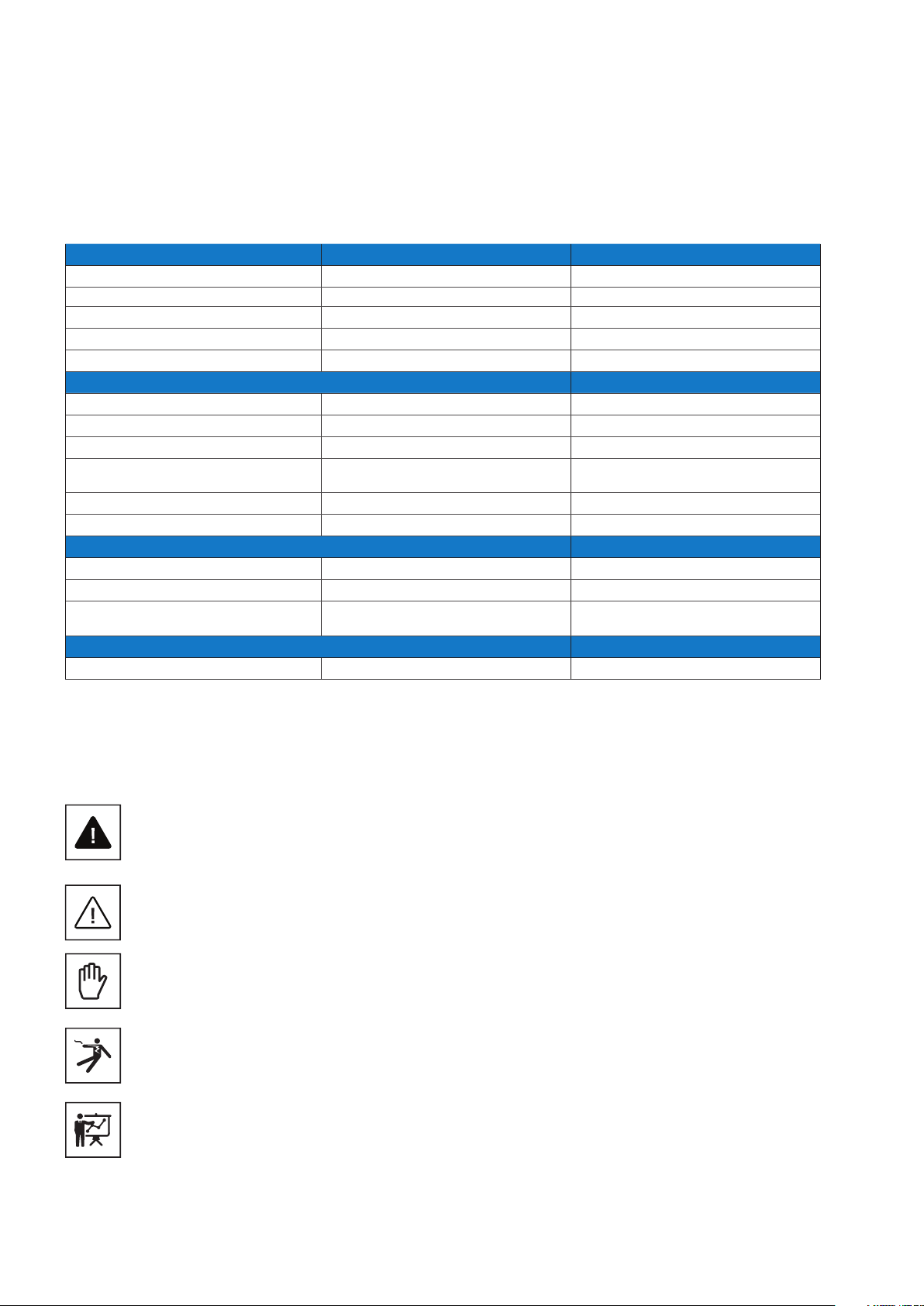
2.2 Suggested protections during the installation
2.3 Protection from electric shock
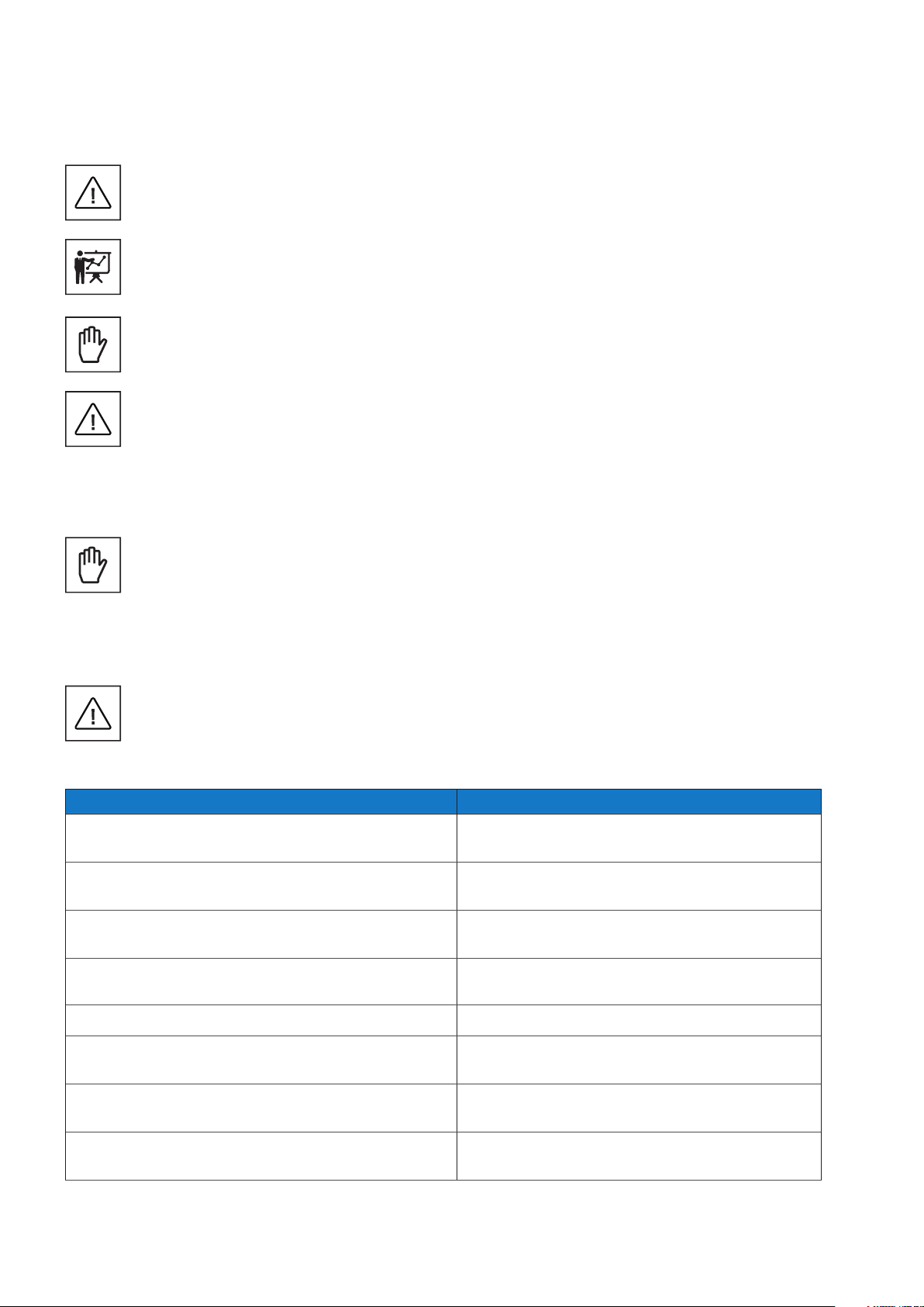
An electric shock can be fatal.
Avoid touching internal or external parts normally live while the system is powered on.
Cables and connections must always be secured, in good condition, insulated and suitably sized.
The equipment was built according to the highest safety standards and equipped with safety devices designed to protect
operators and components.
For obvious reasons, the manufacturer cannot anticipate all potential types of installations and locations where the
equipment will be installed; the customer must therefore clearly inform the manufacturer of specific conditions at the
installation site. Eaton declines any responsibility if the unit is incorrectly installed.
The operators must be correctly instructed. The operators must therefore read and follow the technical instructions
contained in the manual and in the enclosed documentation.
The instructions provided in this manual do not replace the safety regulations of the installation and operational technical
data printed on the products, nor do they replace the current safety standards enforced in the country where the
equipment is installed, and the rules dictated by common sense.
The manufacturer can provide theoretical or practical training to operators, either on their site or on the customer’s
premises, as specified at the time of drawing up the contract.
The equipment must not be used if any operational fault is identified.
Temporary repairs should be avoided; repair work must be carried out only with genuine spare parts, which must be
installed according to the intended use.
The responsibilities deriving from the commercial components are delegated to the respective manufacturers.
Avoid touching the equipment housing during operation. The equipment housing could overheat during operation and
cause burns on contact. The equipment may remain hot even after it is switched off.
In the event of fire, CO2foam extinguishers must be used, and self-vacuum systems must be used to put out fires in
enclosed spaces.
If the noise level exceeds legal limits, the working area must be restricted, and anyone who has access to the area must
wear ear defenders or ear plugs.
During the installation process, special attention must be paid to fixing the equipment and its components. At this stage,
restricting or preventing access to the installation area is recommended.
Professional and qualified personnel are recommended to wear clothing and personal protective equipment (PPE) provided
by their employer. Operators must not wear clothes or accessories that could start fires or produce static electricity, or
any item of clothing that could affect personal safety. When carrying out any operation on the equipment, clothes and
instruments must be suitably insulated.
Professional and qualified personnel must NOT access the equipment with bare feet or wet hands.
The maintenance engineer must always ensure that nobody else is able to reset or operate the equipment during
maintenance and must report any fault or deterioration caused by wear or by aging, in order to restore the correct safety
conditions.
The professional and qualified personnel must always pay attention to the working environment to ensure it is well lit and
has a suitable escape route.
A first aid kit must be provided near the installation site so that it is readily available in case of emergency.