manuals.online logo
Brands
  1. Home
  2. •
  3. Brands
  4. •
  5. Eaton
  6. •
  7. Industrial Electrical
  8. •
  9. Eaton Z-FW-LP Manual

Eaton Z-FW-LP Manual

Z-FW-LP Z-FW-LPD Z-FW-MO Z-FW-LP/MO Z-FW-LPD/MO,,, ,
Maximum number of combinations ( = can be fitted) / Maximale Kombinationsmöglichkeiten ( = anbaubar)ll:
:Possibilité de combinaisons max. ( ê r montées) / Massime possibilità di combinazioni ( = applicabili)ll= pouvant t e
Posibilidades de conexion máxima ( = para montaje adosado) / Možnost kombinace s ostatními p ístroji = lze kombinovat):ř(ll
2x Z-FW-LP
Z-FW-LPD
Z-FW/MO
2 x 1.5 mm² 2 x 2.5 mm²
0.4 Nm
1 x 2.5 mm²
0.8 Nm
4 x 1.5 mm²
Z-HK ZP-AHK, -NHK Z-FW/001- PLSM PLN6 PFIM PFGM Z-MS Z-FW-LP Z-FW-MO,
ZP-IHK, -WHK Z-FW/050 PL7, P 6 Z-FW-LPD *)L FAZ-PN dRCM, FRCdm,
FRCmM, mRCMPLS6
FAZ, FAZT, FAZ6 PF7
PXL PXF
: Z-FW-MO
: Z-FW-MO
Z-FW-LP
Z-FW-LPD/MO
Z-FW-MOZ-FW-LPD
(6TE) mod.
(6TE) mod.
Z-FW-LP/MO
=
=
Z-FW-MO
+
+
NO
*) Z1 0.6 x 3.5
MA-Z-FW-LP+MO.cdr / 12.2019p / IL019014ZU / 150501154
All Rights Reserved / Printed in Austria
Eaton Industries (Austria) GmbH, Eugenia 1, 3943 Schrems, Austria
© 2019 by Eaton Industries (Austria) GmbH, www.eaton.eu/documentation www.eaton.com/recycling
1
Instruction Leaflet
Montageanweisung
Notice d’installation
Instrucciones de montaje
Istruzioni per il montaggio

Инструкция по монтажу
Montagehandleiding

Montagevejledning
Οδηγίες εγκατάστασης
Instruções de montagem
Monteringsanvisning
Asennusohje
Návod k montáži
Paigaldusjuhend
Szerelési utasítás
Montāžas instrukcija
Montavimo instrukcija
Instrukcja montażu
Navodila za montažo
Návod na montáž
Монтажни инструкции
Instrucţiuni de montaj
Upute za montažu
Kullanma Talimatı
Инструкција за монтажу
Intruksjonsblad
Монтажна інструкція
ت ا ة 
Tension d’alimentation
DEL verte service
DEL rouge alarme
Sélecteur de fonctions
Sortie à relais d’alarme
Levier de commande
Levier d’arrêt
Raccord
Essai de d PFIM/PFGMéclenchement sortie à relais
Entrée Marche, Arrêt/Reset
Entrée test
Napájení
LED zelená, Provoz
LED červená, Porucha
Volič funkce
Reléový výstup pro signalizaci poruchy
Páka pro blokování funkce
Páka pro ovládání připojeného zařízení
Propojka
Reléový výstup pro vypínací modul proudových chráničů
Vstupy ZAP, VYP/RESET
Testovací vstup
Alimentazione di tensione
LED verde stato di funzionamento
LED rosso allarme
Selettore di funzione
Uscita relè allarme
Leva di comando
Leva di blocco
Relè d’uscita PFIM - Prova di sgancio
Ingresso/On, Reset/Off
Prova d’ingresso
Tensi n de alimentacióón
LED verde Estado de service
LED jojo Alarma
Selector de funciones
Salida de relé Alarma
Palanca de accionamiento
Palanca de enclavamiento
Salida de relé PFIM - Prueba de disparo
Entrada Cierra, Apertura/Rearme
Entrada Prueba
AUTOM
5x
AUTOM
5x
OFF/RESET
OFF/RESET
Z-FW-LP
Z-FW-LPD
+
+
+
+
13 14
Spannungsversorgung
LED grün Betriebszustand
LED rot Alarm
Funktionswahlschalter
Relaisausgang Alarm
Betätigungshebel
Sperrhebel
Koppelstecker
Relaisausgang FI-Auslöseprüfung
Eingang Ein, Aus/Reset
Eingang Test
7
8
9
10
7
8
9
10
Power supply
LED green Operational
LED red Alarm
Function selector switch
Relay output for Alarm
Actuating lever
Blocking lever
Link
Relay output for RCD tripping test
On input, Off/Reset
Test input
7
8
9
10
7
8
9
10
Z-FW-LPD
U1-U2 24-48 V=
13-14 5 A/250 V~
Z-FW-LP
U1-U2 220 - 240 V~, 50Hz
13-14 5 A/250 V~
7
8
9
10
7
8
9
10
Z-FW-MO
P1 P2 400V~ max.
ON-C-OFF 24 - 230 V AC DC
T1 T2 24 - 230 V AC DC
8
9
10
ON
ON
OFF/RESET
OFF/RESET
Z-FW-MO
8
910
6
4
2
5
3
7
Attention!
In the event of the power supply being interrupted the Z-FW... saves the
last operating state and retains this state when the power supply is
restored.
Never operate the Z-FW... without the or fitted.MCB RCCB
The Z-FW... does not switch directly after a command.
Remote switching is possible in all operating modes except in OFF.
The blocking lever in the position prevents unintentional switching.
Provide a suitable warning plate in a visible location on the Z-FW...
The tripping of an allows the mains supply to be switched back onRCCB
momentarily in the event of a fault. Therefore ensure suitable measures for the
protection of persons.
A class C surge arrester connected upstream must be provided in the load
installation.
GB Achtung!
Bei Unterbrechung der Versorgungsspannung speichert Z-FW...
letzten Zustand und nimmt diesen nach Spannungsrückkehr wieder ein.
Z-FW... nie ohne angebauten LS bzw. FI betreiben.
Z-FW... schaltet nicht unmittelbar nach einem Befehl.
Ferngesteuertes Schalten mit Z-FW-MO ist möglich, außer in OFF.
Der Sperrhebel verhindert in Position unerwartete Schaltvorgänge.
Warnschild sichtbar beim Z-FW... anbringen.
Die Freiauslösung eines FI lässt ein sehr kurzes Wiedereinschalten der
Netzspannung bei bestehenden Fehlern zu, deshalb Personenschutz beachten.
Ein vorgeschalteter Überspannungsschutz der Klasse C muss in der
Verbraucheranlage vorhanden sein.
D
MA-Z-FW-LP+MO.cdr / 12.2019p / IL019014ZU / 150501154
All Rights Reserved / Printed in Austria
Eaton Industries (Austria) GmbH, Eugenia 1, 3943 Schrems, Austria
© 2019 by Eaton Industries (Austria) GmbH, www.eaton.eu/documentation www.eaton.com/recycling
2
Attention!
En cas de coupure de la tension d’alimentation, Z-FW... mémorise le
dernier état et reprend celui-ci après le reour de la tension.
Ne jamais faire fonctionner le Z-FW... sans l’avoir monté sur le
MCB RCCBet/ou le
Z-FW... ne commute pas immédiatement après un ordre.
Commutation à distance avec Z-FW-MO possible dans toutes les positions sauf
en OFF.
Le levier d’arr .êt en position empêche les commutations intempestives
Bien mettre en é Z-FW...vidence la plaque d’avertissement sur le
Le dé autorise un trRCCBclenchement libre d’un ès bref réenclenchement de la
tension du secteur, alors que les défauts subsistent ; il faut donc veiller à la
protection des personnes.
Le circuit d’alimentation du récepteur doit contenir en amont une protection
contre les surtensions de la classe C.
Attenzione
Con l’interruzione della tensione di alimentazione il Z-FW... memorizza
l’ultimo stato di esercizio e rileva ancora lo stesso dopo il ripristino della
Non azionare mai il Z-FW... senza oMCB RCCB
Z-FW... non commuta immediatamente dopo un comando.
Il comando a distanza è possible in tutti gli stati di funzionamento eccetto in OFF.
La leva di bloccaggio , nella posizione impedisce manovre accidentali.
Apporre targhetta monitrice sul Z-FW...
Lo sgancio di un causa un breve tempo di reinserzione della tensione diRCCB
rete in presenza di guasto. Per questo fare attenzione alla protezione delle
persone.
Nell’impianto utilizzatore deve essere prevista una protezione contro la
sovratensione della classe C.
¡Advertencia!
En caso de corte de la tensi n de alimentaci Z-FW... memoriza eló ón,
ú ón.ltimo estado y lo recupera al restablecerse la tensi
Z-FW... no se debe poner nunca en funcionamiento sin haberlo montado en
o.MCB RCCB
Z-FW... no conmuta inmediatamente después de recibir una orden.
La maniobra controlada a distancia es posble en todos los modos de
funcionamiento excepto en APERTURA.
La palanca de enclavamiento impide en la posición maniobras de
cierre/apertura intempestivas.
Montar la placa de aviso junto al Z-FW... de modo que sea visible.
El disparo libre de un permite una reconexiRCCB ón muy breve de la tensión de
red en caso de un defecto. Es preciso tener en cuenta, por este motivo, las
medidas de seguridad personal pertinentes.
El circuito de alimentación del receptor debe tener “aguas arriba” una protección
contra las sobretensiones de la clase C.
Notes
First connect Z-FW..., Z-FW-LP. to the power supply and then set the
function selector switch to AUTOM5x bzw. ON.
The device is fully operational approximately 40 s after the power supply is
switched on. During this time no switching commands are received and the
flashing green LED indicates charging.
Hinweise
An Z-FW..., Z-FW-LP. zuerst Spannungsversorgung anlegen und dann die
Funktionswahl-schalter auf AUTOM5x bzw. ON stellen.
Ca. 40 s nach Einschalten der Spannung ist die volle Betriebsbereitschaft
erreicht.
Während dieser Zeit ist keine Befehlsannahme für Schaltbefehle gegeben
und die blinkende grüne LED zeigt den Ladevorgang an.
Remarques
D’abord appliquer la tension d’alimentation sur le Z-FW..., Z-FW-LP. et
ensuite régler les sélecteurs de fonctions sur AUTOM5x ou ON. L’appareil
est opérationnel environ 40 sec. après mise sous tension. Pendant ce
temps, les ordres de commutation ne sont pas reçus et la DEL verte
clignotante signale le chargement.
Informazioni
Sul Z-FW..., Z-FW-LP. prima applicare tensione di alimentazione e poi
impostare il selettore di funzione su AUTOM5x bzw. ON.
Circa 40 s dopo l’inserzione della tensione viene raggiunta la totale
funzionalità. In questo lasso di tempo non è possibile eseguire alcun
comando e il LED verde lampeggiante indica l’operazione di carico.
Obsevaciones
En primer lugar aplicar a Z-FW..., Z-FW-LP. tensión de alimentación, y a
continuación, ajustar el selector de funciones a AUTOM5x bzw. ON. La
disponibilidad de servicio completa se alcanza unos 40 s tras la conexión
de la tensión. Durante este tiempo no se puede recibir ninguana orden de
conmutación.
El LED verde intermitente indica el proceso de carga.
Poznámka
Nejd íve p ipojte napájení k Z-FW-..., Z-FW-LP. a pak nastavte voliřř č
funkce do polohy AUTOM 5x resp.ON.
P ístroj je p ipraven k provozu asi 40 sec po p ipojení napájení. B hemřř ř ě
této doby bliká zelená LED dioda a nejsou p ijímány žádné vstupníř
ovládací impulsy.
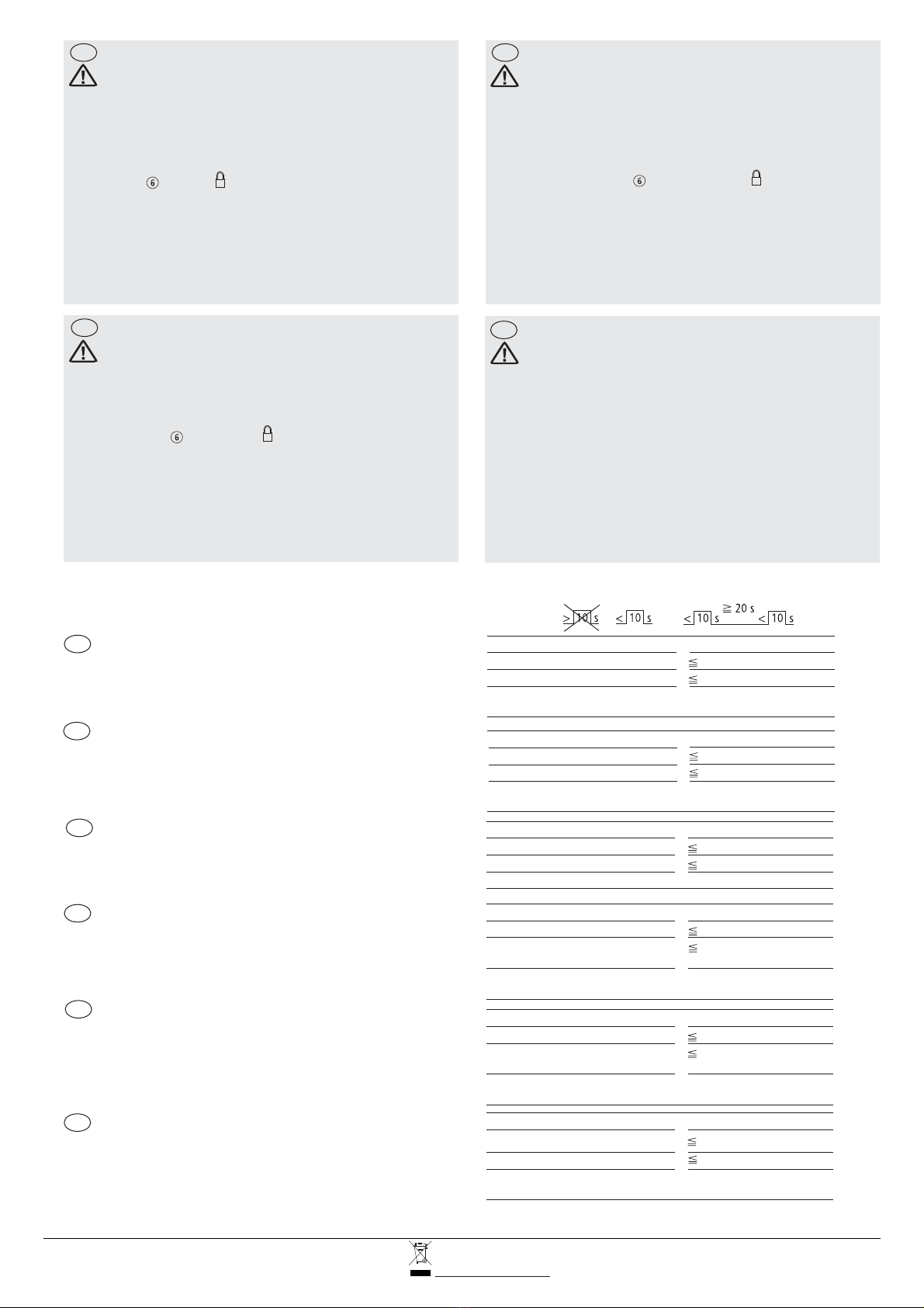
Mindest-Impulsdauer 1 s: 50 Hz, 3 s: < 50 Hz
Wiedereinschaltzeiten 20 s; 30 s; 70 s; 10 min.; 1 h
Schaltverzugszeit ab Befehl 25 s
Betriebsbereitschaft für Schaltvorgänge 40 s nach Einschaltung
Betriebsspannung
Minimum pulse duration 1 s: 50 Hz, 3 s: < 50 Hz
Resetting times 20 s; 30 s; 70 s; 10 min.; 1 h
Switching delay time after command 25 s
Ready for receiving switching command 40 s after switching on power
supply voltage
Minimální délka impulsu 1 s: 50 Hz, 3 s: < 50 Hz
Intervaly resetování 20 s; 30 s; 70 s; 10 min.; 1 h
Spínací zpoždění po ovl. impulsu 25 s
Připravenost zařízení pro příjem 40 s po připojení napájení
ovládacích impulsů
Durée d’impulsions min. 1 s: 50 Hz, 3 s: < 50 Hz
Temps de réenclenchement 20 s; 30 s; 70 s; 10 min.; 1 h
Durée max. d’actionnement 25 s
Appareil opérationnel 40 s après mise sous tension
Minima durata dell’impulso 1 s: 50 Hz, 3 s: < 50 Hz
Tempi di reinserzione 20 s; 30 s; 70 s; 10 min.; 1 h
Ritardo di commutazione dopo 25 s
l comando
Pronto per il funzionamento per 40 s dopo la messa in tensione
operazioni di manovra
Duración mínima de impulso 1 s: 50 Hz, 3 s: < 50 Hz
Tiempos de rexonexión 20 s; 30 s; 70 s; 10 min.; 1 h
Tiempo de retardo después de la 25 s
orden de mando
Disponibilidad de servicio para 40 s tras conectarse la tensión
recibir órdenes de mando. de empleo
CZ
F E
I
CZ
I
D
F
E
Eingangssignale / Input signals / Signaux d’entrée/Segnali d’engresso /
Señales de entrada / Vstupní impulzy
Pozor!
V případě přerušení napájecího napětí dojde k zapamatování stavu a jeho
obnovení po připojení napájení.
Nikdy nezapínejte Z-FW... bez ovládaného přístroje.
Dálkové ovládání je možné ve všech režimech kromě polohy OFF (vypnuto).
Páka pro blokování funkce mechanicky zamezuje funkci.
Umístěte výstražný štítek na viditelném místě na Z-FW...
Po elektrickém vybavení proudového chrániče je opět připojen k napájecímu
napětí. Toto musí být zohledněno při ochraně zdraví osob před úrazem el.
proudem.
V napájecím obvodu musí být předřazený svodič přepětí třídy C.
Z-FW... Nereaguje okamžitě na ovládací impulsy.
GB
MA-Z-FW-LP+MO.cdr / 12.2019p / IL019014ZU / 150501154
All Rights Reserved / Printed in Austria
Eaton Industries (Austria) GmbH, Eugenia 1, 3943 Schrems, Austria
© 2019 by Eaton Industries (Austria) GmbH, www.eaton.eu/documentation www.eaton.com/recycling
3
Mounting example, Montagebeispiel, Exemple de montage, Esempio di montaggio, Ejemplo de montaje, Příklad montáže
Z-FW-LPD
Z-FW-LP
MCB
1p, 2p, 3p,
4p (3p+N)
Z-FW-MO
11
10
8
2x
Z-FW-LPD
Z-FW-LP
Z-NHK
Z-FW-MO
8
2x
Z-FW-LP
Z-FW-LPD
Z-FW/0..
Z-HK
RCCB-2p
RCCB-2p
RCCB-4p
RCCB-4p
Z-FW-
MO
Z-FW-
MO
OK
OK
NO
NO
MA-Z-FW-LP+MO.cdr / 12.2019p / IL019014ZU / 150501154
All Rights Reserved / Printed in Austria
Eaton Industries (Austria) GmbH, Eugenia 1, 3943 Schrems, Austria
© 2019 by Eaton Industries (Austria) GmbH, www.eaton.eu/documentation www.eaton.com/recycling
4
Unlocking
Entriegelung
Dvé errouillage
Sblocco
Desenclavamiento
Odblokování
Sealing
Plombierung
Plombage
Piombature
Precintado
Plombování
Interlock
Verriegelung
Verrouillage
Interblocco
Enclavamiento
Blokování
Applying control voltage to U1-U2:
lThe green LED flashes
After approx. 40 s
- Z-FW-LP. and Z-FW-MO are operational
- Green LED is permanently lit
lThe red LED indicates alarms.
Red LED flashing:
- or trippedMCB RCCB
- Output 13-14 closed permanently.
Red LED permanently lit:
indicated blocked alarm status
- Output 13-14 closed permanently.
- Switch on attempt via C-ON only possible after Reset.
Reset via
- Function selector switch in OFF or
- Off command on C-OFF
Operating mode selection via function selector switch
Automatic mode with five reset attempts (AUTOM 5 x):
MCB RCCBor trips again.
Z-FW... indicates trip
- Output 13-14 gloses momentarily
- Red LED flashes
Four more restart attempts are made after 30 s, 70 s, 10 min., 1h.
PLSM or PFIM switches on within the five attempts
lZ-FW... ends operation
Fifth unsuccessful restart attempt
lZ-FW... switches to Alarm status
- Output 13-14 permanently closed
- Red LED permanently lit
Reset after fault rectified
lZ-FW-LPN no automatical function
ALARM, RESET status:
Z-FW... reaches maximum number of resets (5 x),
permanent fault present
lZ-FW... switches to Alarm status
- Output 13-14 permanently closed
- Red LED permanently lit
Reset via
- Function selector switch in OFF/RESET or
- Off comand to C-OFF
Switching on C-ON possible or manually on the ,MCB RCCB
Faulty remot tripping test and blocked actuating lever also cause alarm status.
lZ-FW-LPN: switching off the MCB/RCD the alarm reay (output 13-14) with be
shortly closed (~300ms)
Remote tripping test, Z-FW-LP.+Z-FW-MO
Select Z-FW/ø.. (Z-FW/003 - 30mA FI) according to the rated residual current of
the .RCCB
Apply Test command to input T1-T2.
lZ-FW/ø.. (Z-FW/003 - 30mA ) trips immediately.RCCB RCCB
- Z-FW-LP. resets automatically .RCCB
ldoes not trip or reset attempt unsuccessfulRCCB
Z-FW-LP. switches to Alarm status
- Output 13-14 permanently closed
- Red LED permanently lit
Reset after fault rectified
lFSE no remote tripping test possible
GB Anlegen der Steuerspannung an U1-U2:
lDie grüne LED blinkt
Nach ca. 40 s
- Z-FW-LP. und Z-FW-MO sind betriebsbereit
- Grüne LED leuchtet konstant
lDie rote LED zeigt Alarmzustände an
Rote LED blinkt:
- oder hat ausgelöstLS FI
- Ausgang 13-14 schließt mit jeder Auslösung kurzzeitig
Rote LED leuchtet konstant:
bedeutet blockierter Alarmzustand
- Ausgang 13-14 schließt dauerhaft
- Einschaltversuch über C-ON erst nach Reset möglich
Reset durch:
- Funktionswahlschalter in OFF oder
- Aus-Befehl an C-OFF
Wahl der Betriebsart durch Funktionswahlschalter
Automatischer Betrieb mit fünf Einschaltversuchen (AUTOM 5 x):
LS oder FI löst erneut aus.
Z-FW... meldet Auslösung
- Ausgang 13-14 schließt kurzzeitig
- rote LED blinkt
Vier weitere Wiedereinschaltversuche erfolgen nach 30 s, 70 s, 10 min., 1h.
LS FIoder schaltet innerhalb fünf Versuche ein
lZ-FW... beendet Vorgang
Fünfter vergeblicher Wiedereinschaltversuch
lZ-FW... geht in Alarmzustand
- Ausgang 13-14 schließt konstant
- Rote LED leuchtet konstant
Reset nach Fehlerbehebung
lZ-FW-LPN hat keinen automatischen Betrieb
Betriebszustand ALARM, RESET:
Z-FW... erreicht maximale Wiedereinschaltzahl (5 x),
Dauerfehler steht an
lZ-FW... geht in Alarmzustand
- Ausgang 13-14 schließt konstant
- Rote LED leuchtet konstant
Reset durch
- Funktionswahlschalter in OFF/RESET oder
- Aus-Befehl an C-OFF
Einschalten an C-ON möglich oder manuell am ,LS FI
Fehlerhafte Fern-Auslöseprüfung und blockierter Betätigungshebel
führen ebenfalls zum Alarmzustand.
lZ-FW-LPN: bei Ausschalten des angebauten Schaltgerätes wird das Alarmrelais
(Ausgang 13-14) kurzzeitig angezogen (ca. 300ms)
Fern-Auslöseprüfung, Z-FW-LP.+Z-FW-MO
Z-FW/ø.. (Z-FW/003 - 30mA FI) entsprechend dem Bemessungsfehlerstrom des
FI auswählen.
Test-Befehl an T1-T2 legen.
lZ-FW/ø.. (Z-FW/003 - 30mA FI) löst aus.FI
- Z-FW-LP. schaltet automatisch wieder ein.FI
llöst nicht aus, bzw. Wiedereinschaltversuch misslingtFI
Z-FW-LP. geht in Alarmzustand
- Ausgang 13-14 schließt konstant
- Rote LED leuchtet konstant
Reset nach Fehlerbehebung
lbei FSE keine Fernauslöseprüfung (da kein Wiedereinschalten möglich)
D
MA-Z-FW-LP+MO.cdr / 12.2019p / IL019014ZU / 150501154
All Rights Reserved / Printed in Austria
Eaton Industries (Austria) GmbH, Eugenia 1, 3943 Schrems, Austria
© 2019 by Eaton Industries (Austria) GmbH, www.eaton.eu/documentation www.eaton.com/recycling
5
Appliquer la tension de commande sur U1-U2:
lLa DEL verte clignote :
Après 40 s env.
- Z-FW-LP. et Z-FW-MO opérationnels
- DEL verte allumée en permanence
lLa DEL rouge signale les états d’alarme
La DEL rouge clignote :
- ou a déclenchéMCB RCCB
- La sortie 13-14 se ferme momentanément pour chaque déclenchement.
La DEL rouge est allumée en permanence :
signifie état d’alarme bloqué
- La sortie 13-14 se ferme en permanence
- Un essai d’enclenchement par C-ON n’est possible qu’après avoir
actionné le bouton reset.
Reset par :
- Sélecteur de fonctions en OFF ou
- Ordre d’Arrêt sur C-OFF
Choix du mode par sélecteur de fonctions
Fonctionnement automatique avec cinq essais d’enclenchement
(AUTOM 5 x):
MCB RCCBou déclenche à nouveau
Z-FW... signale déclenchement
- Sortie 13-14 se ferme momentanément
- DEL rouge clignote
Quatre autres essais de réenchlenchement ont lieu après 30 s, 70 s, 10 min., 1h.
MCB RCCBou enclenche en moins de cinq essais
lZ-FW... termine le cycle
Cinquième essai de réenchlenchement en vain
lZ-FW... passe à l’état d’alarme
- Sortie 13-14 se ferme en permanence
- DEL rouge s’allume en permanence
Reset après élimination du défaut
lZ-FW-LPN aucune fontion automatique
Etat de service ALARM, RESET:
Z-FW... atteint le nombre max. de réenclenchements (5 x),
erreur permanente
lZ-FW... passe à l’état d’alarme
- Sortie13-14 se ferme en permanence
- DEL rouge s’allume en permanence
Reset par
- Sélecteur de fonctions en OFF/RESET ou
- Ordre d’Arrêt sur C-OFF
Possibilité d’enclencher le avec un ordre de marche sur C-ON ouMCB/RCCB
manuellement.
L’essai de déclenchement infructueux à distance ainsi qu’un blocage du levier de
commande provoquent également l’alarme.
lZ-FW-LPN: I a commuation du MCB/RCD le relais d’alarme (rendement 13-14)
sera sous pen clôturêe
Essai de déclenchement à distance, Z-FW-LP.+Z-FW-MO
Choisir le Z-FW/ø.. (Z-FW/003 - 30mA ) en fonction du courant assigné deRCCB
défaut du . Appliquer un ordre de test sur l’entrée T1-T2.MCB
lZ-FW/ø.. (Z-FW/003 - 30mA ) fait déclencher le instantanement.RCCB RCCB
- Z-FW-LP. réenclenche automatiquement le .RCCB
lne déclenche pas ou l’essai de réenclenchement échoueRCCB
Z-FW-LP. passe à l’état d’alarme
- La sortie 13-14 se ferme en permanence
- DEL rouge s’allume en permanence
Reset après élimination du défaut
lFSE aucun essai de déclenchement à distance possible
Applicazione della tensione di comandu su U1-U2:
lIl LED lampeggia
Dopo circa 40 s
- il Z-FW-LP. o Z-FW-MO è pronto al funzionamento
- il LED verde si illumina costantemente
lIl LED rosso visualizza stati di allarme
Il LED rosso lampeggia:
- Il o ha sganciatoMCB RCCB
- L’uscita 13-14 chiude brevemente ad ogni sgancio
Il LED rosso si illumina costantemente:
significa stato d’allarme bloccato
- Uscita 13-14 chiude permanentemente
- Possibile tentativo di inserzione su C-ON solo dopo il Reset
Reset attraverso:
- selettore di funzione in OFF oppure
- comando OFF su C-OFF
Scelta del modo di funzionamento attraverso il selettore di funzione
Funzionamento automatico con 5 prove di inserzione (AUTOM 5 x):
Il o sgancia di nouvo.MCB RCCB
Il Z-FW... comunica lo sgancio.
- Uscita 13-14 chiude per un breve periodo
- Il LED rosso lampeggia
Quattro altre prove di inserzioni si susseguono dopo 30 s, 70 s, 10 min., 1h.
Il o inserisce entro 5 prove.MCB RCCB
lIl Z-FW... termina il processo
Quinta prova fallita di inserzione
lIl Z-FW... va in stato di allarme
- Uscita 13-14 chiude costantemente
- Il LED rosso si illumina costantemente
Reset dopo l’eliminazione del guasto
lZ-FW-LPN > nessuna funzione automatica
Stato di funzionamento ALARM, RESET:
Il Z-FW... raggiunge il numero massimo di reinserzioni (5 x),
E’presente un errore continuo.
lIl Z-FW... va in stato di allarme
- Uscita 13-14 chiude costantemente
- Il LED rosso si illumina costantemente
Reset attraverso
- selettore di funzione in OFF/RESET
- comando OFF su C-OFF
Manovra su C-ON possibile o manualmente su MCB/RCCB
La prova di sgancio a distanza difettosa e la leva di comando
bloccata provocano in ogni caso lo stato di allarme.
lZ-FW-LPN: > la commutazione del MCB/RCD il relé dell’allarme (uscita 13-14)
sara presto chiusa
Prova di sgancio a distanza, Z-FW-LP.+Z-FW-MO
Selezionare la corrente di guasto corrispondente al Z-FW/ø..
RCCB(Z-FW/003-30mA )
Applicare un segnale di prova all’ingresso T1-T2.
lIl Z-FW/ø.. (Z-FW/003 - 30mA ) sgancia il immediatamente.RCCB RCCB
RCCB- Il Z-FW-LP. commuta il
reinserisce automaticamente.
lIl non sgancia, tentative di reinserzione fallitoRCCB
Il Z-FW-LP. va in stato di allarme
- Uscita 13-14 chiude costantemente
- Il LED rosso si illumina
Reset dopo l’eliminazione del guasto
lFSE > nessuna prova di scatenamento a distanca possibile
I
F
MA-Z-FW-LP+MO.cdr / 12.2019p / IL019014ZU / 150501154
All Rights Reserved / Printed in Austria
Eaton Industries (Austria) GmbH, Eugenia 1, 3943 Schrems, Austria
© 2019 by Eaton Industries (Austria) GmbH, www.eaton.eu/documentation www.eaton.com/recycling
6
Aplicar la tensión de mando a U1-U2:
lEl LED verde destella.
Tras 40 s aprox.
- Z-FW-LP. o Z-FW-MO está disponible para servicio
- LED verde está permanentemente iluminado
lEl LED rojo señala los estado de alarma
LED rojo destella:
- o disparadoMCB RCCB
- Salida 13-14 se cierra momentaneamente con cada disparo
LED rojo está permanentemente iluminado:
significa estado de alarma bloqueado
- Salida 13-14 cerrada permanentemente
- La prueba de conexión a través de C-ON sólo es posible tras haber
accionado el botón de rearme.
Rearme mediante:
- Selector de funciones en OFF ó
- orden de apertura a C-OFF
Selección del modo de funcionamiento mediante selector de
funciones
Modo automático con cinco pruebas de conexión (AUTOM 5 x):
MCB RCCBó vuelve a disparer
Z-FW... señaliza disparo
- Salida 13-14 se cierra momentaneamente
- LED rojo destella
Tienen lugar cuatro pruebas de rearme adicionales transcurridos
30 s, 70 s, 10 min., 1h.
MCB RCCBó se conectan durante las cinco pruebas siguientes
lZ-FW... finaliza proceso
Quinto intento fallido de rearme
lZ-FW... pasa a estado de alarma
- Salida 13-14 cerrada permanentemente
- LED rojo se ilumina permanentemente
Rearme tras defecto
lZ-FW-LPN > ninguna función automática
Estado de eliminación de ALARMA, REARME:
Z-FW... alcanza el tiempo máximo de rearme (5 x),
se mantiene error permanente.
lZ-FW... pasa a estado de alarma
- Salida 13-14 cerrada permanentemente
- LED rojo se ilumina permanentemente
Rearme mediante
- Selector de funciones en OFF/RESET o bien
- orden de apertura a C-OFF
Posibilidad de mando en C-ON o bien manualmente en el MCB/RCCB
Prueba de disparo a distancia defectuosa y palanca de
accionamiento bloqueada también dan lugar al estado de alarma.
lZ-FW-LPN: > la commutación del MCB/RCD el ralis del alarmar (salida 13-14)
será cerrada pronto
Prueba di disparo a distancia, Z-FW-LP.+Z-FW-MO
Seleccionar Z-FW/ø.. (Z-FW/003 - 30mA ) de acuerdo con la intensidadRCCB
asignada de defecto del MCB
Aplicar señal de prueba a entrada T1-T2
lZ-FW/ø.. (Z-FW/003 - 30mA ) dispara inmediatamente.RCCB RCCB
- Z-FW-LP. rearma automáticamente RCCB
lno dispara o falla la prueba de rearmeRCCB
Z-FW-LP. pasa a estado de alarma
- Salida 13-14 cerrada permanentemente
- LED rojo se ilumina permanentemente
Rearme tras eliminarse el defecto
lFSE > ninguna prueba que dispara alejada posible
ECZ Připojení ovládacího napětí U1-U2:
lZelená dioda LED bliká, asi po 40 s
- Z-FW-LP. a Z-FW-MO jsou připravena
- Zelená dioda LED svítí trvale
lČervená dioda indikuje stav poruchy
Červená LED bliká:
- Došlo k vybavení jističe nebo proudového chrániče (stav poruchy)
- Výstup 13-14 je sepnutý
Červená LED svítí trvale:
- Indikuje stav poruchy v blokované poloze
- Výstup 13-14 je sepnutý
- Zapnutí je možné pouze po přivedení signálu na vstup C-ON (RESET).
Způsoby RESETování
- funkční volič v poloze OFF
- ovládací povel na svorkách C-OFF
Volba pracovního režimu je možná přes funkční otočný volič.
Automatický mód s 5 pokusy zapnutí (AUTOM 5x):
Dojde k vybavení jističe nebo proudového chrániče.
Z-FW... signalizuje poruchu
-Výstup 13-14 je sepnutý
- Červená dioda bliká
Přístroj se pokusí zapnout připojené zařízení po 20 s, 30 s, 70 s, 10 min., 1h.Z-
FW... přestane po pátém neúspěšném pokusu
lZ-FW... se přepne do stavu hlášení chyby
-Výstup 13-14 je sepnutý
- Červená dioda svítí trvale
lJe nutné přovést RESET přístroje
Způsoby RESETování
- funkční volič v poloze OFF
- ovládací povel na svorkách C-OFF
lZ-FW-LPN > Bez funkce automatického zapíinání
Stav poruchy:
Z-FW... dosáhne maximálniho množství pokusů (5 x) a je ve stavu poruchy
lZ-FW... se přepne do stavu hlášení chyby
-Výstup 13-14 je sepnutý
- Červená dioda svítí trvale
- výstup 13-14 trvale sepnutý
Způsoby RESETování
- funkční volič v poloze OFF
- ovládací povel na svorkách C-OFF
- je možné zapnutí chrániče a jističe přívodem povelu na svorky C-ON nebo ručně
- Chybně vykonaný dálkový test nebo blokování zapínací páky také způsobuje stav
alarmu.
lPřizapínáni jističe/proudového chrániče výstupni relé (výstupy 13-14) Krátce
sepne
Dálkový test, Z-FW-LP.+Z-FW-MO
Vyberte podle reziduálního proudu chrániče.Z-FW/ .. (Z-FW/003 - 30mA )øRCCB
Přivete testovací povel na svorky T1-T2.
lvypne proudový chránič okamžitě.Z-FW/ .. (Z-FW/003 - 30mA )øRCCB
- Z-FW-LP. resetuje chránič automaticky.
Pokud proudový chránič nevypne nebo je testovací pokus neúspěšný, Z-FW-LP se
přepne do stavu hlášení chyby
-Výstup 13-14 je sepnutý
- Červená dioda svítí trvale
Je nutné provést RESET přístroje
lFSE > Bez možnosti vzdáleného testováni
MA-Z-FW-LP+MO.cdr / 12.2019p / IL019014ZU / 150501154
All Rights Reserved / Printed in Austria
Eaton Industries (Austria) GmbH, Eugenia 1, 3943 Schrems, Austria
© 2019 by Eaton Industries (Austria) GmbH, www.eaton.eu/documentation www.eaton.com/recycling
7
13 14
13 14
13-14
20 s 30 s 70 s 10 min 1 h
Circuit examples, Schaltungsbeispiele, Exemples de schémas, Esempi di comando, Ejemplos de maniobra, Příklady zapojení
Automatic reset
Autom. Wiedereinschaltung
Réenclenchement automatique
Reinserzione automatica
Rearme automático
Automatické resetování
Remote tripping test / Fern-Auslöseprüfung / Essai déclenchement à distance
Prova di sgancio a distanza / Prueba de disparo a distanci / Dálkový test vypnutí
Reset after alarm stop 5x
Rückstellung nach ALARM-stopp 5x
Remise à zèro après stop alarme 5x
Reset dopo stop d’allarme 5x
Reset posterior a 5 reconexiones
Resetování po 5 neúsp šných pokusechě
A: Z-FW-LP.
oder / or / ou
oder / or / ou
LED
13-14
B: Z-FW-MO
C: Z-FW-MO
Remote switching / Fernschaltung / Commande à distance
Apertura a distanza / Mando a distancia / Dálkové zapínání
AUTOM 5 x
OFF/RESET Autom 5 x OFF/RESET AUTOM5x ON ON
AUTOM 5 x
AUTOM 5 x
220 - 240 V 50 Hz
24-48 V=
PLSM-B4/-HS
PLSM-B4/-HS
Z-FW-LP.
RCCB
Z-FW-LPD
RCCB
C-ON C-OFF
RCCB
RCCB
RCCB
PLSM, PFIM
Z-FW-LP.
Z-FW-LP. + Z-FW-LPD
Z-FW-LPD
C OFF C OFF C OFF
1
OFF/RESET OFF/RESET
AUTOM
5x ON
AUTOM
5x ON
OFF/RESET OFF/RESET
Selector: Z-FW-LP. Selector: Z-FW-MO
23
RCCB
24 - 48V DC (-LPD/MO)
220 - 240VAC (-LP/MO)
MA-Z-FW-LP+MO.cdr / 12.2019p / IL019014ZU / 150501154
All Rights Reserved / Printed in Austria
Eaton Industries (Austria) GmbH, Eugenia 1, 3943 Schrems, Austria
© 2019 by Eaton Industries (Austria) GmbH, www.eaton.eu/documentation www.eaton.com/recycling
8

This manual suits for next models

5

Other Eaton Industrial Electrical manuals

Eaton MODAN 6000 Manual

Eaton

Eaton MODAN 6000 Manual

Eaton COOPER POWER SERIES User manual

Eaton

Eaton COOPER POWER SERIES User manual

Eaton FAZ/FIP-XDWM Manual

Eaton

Eaton FAZ/FIP-XDWM Manual

Eaton COOPER POWER SERIES Manual

Eaton

Eaton COOPER POWER SERIES Manual

Eaton CI-K2 Series Manual

Eaton

Eaton CI-K2 Series Manual

Eaton NZM4-XTD-0 Manual

Eaton

Eaton NZM4-XTD-0 Manual

Eaton MODAN F Manual

Eaton

Eaton MODAN F Manual

Eaton CROUSE-HINDS Ex - d Series User manual

Eaton

Eaton CROUSE-HINDS Ex - d Series User manual

Eaton P3 XM Series Manual

Eaton

Eaton P3 XM Series Manual

Eaton Series NRX User manual

Eaton

Eaton Series NRX User manual

Eaton Ulusoy HMH24-04 User manual

Eaton

Eaton Ulusoy HMH24-04 User manual

Eaton Ulusoy HMH24-02 User manual

Eaton

Eaton Ulusoy HMH24-02 User manual

Eaton MTL SUM5 User manual

Eaton

Eaton MTL SUM5 User manual

Eaton PT 10 User manual

Eaton

Eaton PT 10 User manual

Eaton DILM17-21 Series Manual

Eaton

Eaton DILM17-21 Series Manual

Eaton VacClad-W Programming manual

Eaton

Eaton VacClad-W Programming manual

Eaton E57 Series Manual

Eaton

Eaton E57 Series Manual

Eaton Memera Series Manual

Eaton

Eaton Memera Series Manual

Eaton Moeller EU5E-SWD-8DX Manual

Eaton

Eaton Moeller EU5E-SWD-8DX Manual

Eaton RMQ22 Manual

Eaton

Eaton RMQ22 Manual

Eaton Power Xpert UX 12 User manual

Eaton

Eaton Power Xpert UX 12 User manual

Eaton DILM12-XSL Manual

Eaton

Eaton DILM12-XSL Manual

Eaton Tandem ELF Current-Limiting Dropout Fuse User manual

Eaton

Eaton Tandem ELF Current-Limiting Dropout Fuse User manual

Eaton MSFI-80A Manual

Eaton

Eaton MSFI-80A Manual

Popular Industrial Electrical manuals by other brands

Ortronics MM6VML706 Assembly instructions

Ortronics

Ortronics MM6VML706 Assembly instructions

hager VE312DN Mounting instructions

hager

hager VE312DN Mounting instructions

Crestron FlipTop FT2 Series quick start

Crestron

Crestron FlipTop FT2 Series quick start

Murata GRT188C81A106ME13 Series Reference sheet

Murata

Murata GRT188C81A106ME13 Series Reference sheet

Murata GRM0225C1C150JD05 Series Reference sheet

Murata

Murata GRM0225C1C150JD05 Series Reference sheet

Siemens SIVACON 8PS BD2 Series installation instructions

Siemens

Siemens SIVACON 8PS BD2 Series installation instructions

Murata GRM1885C2A300JA01 Series Reference sheet

Murata

Murata GRM1885C2A300JA01 Series Reference sheet

Gewiss MTSA Series quick start guide

Gewiss

Gewiss MTSA Series quick start guide

ABB Smile 41 AS-i Series Original instructions

ABB

ABB Smile 41 AS-i Series Original instructions

Murata GRM31CE70G476ME15 Series Reference sheet

Murata

Murata GRM31CE70G476ME15 Series Reference sheet

Murata GRM1885C1H7R2DA01 Series Reference sheet

Murata

Murata GRM1885C1H7R2DA01 Series Reference sheet

Murata GRM0335C1H7R5CA01 Series Reference sheet

Murata

Murata GRM0335C1H7R5CA01 Series Reference sheet

Elvox 692P/M Wiring instructions

Elvox

Elvox 692P/M Wiring instructions

Murata GRM216R71H471KA01 Series Reference sheet

Murata

Murata GRM216R71H471KA01 Series Reference sheet

Murata GRM0225C1E5R2DA03 Series Reference sheet

Murata

Murata GRM0225C1E5R2DA03 Series Reference sheet

Murata GRM219C80J475KE19 Series Reference sheet

Murata

Murata GRM219C80J475KE19 Series Reference sheet

Murata GRM155C71A225KE11 Series Reference sheet

Murata

Murata GRM155C71A225KE11 Series Reference sheet

PCB 1102-01A Installation and operating manual

PCB

PCB 1102-01A Installation and operating manual

manuals.online logo
manuals.online logoBrands
  • About & Mission
  • Contact us
  • Privacy Policy
  • Terms and Conditions

Copyright 2025 Manuals.Online. All Rights Reserved.