manuals.online logo
Brands
  1. Home
  2. •
  3. Brands
  4. •
  5. Eaton
  6. •
  7. Industrial Equipment
  8. •
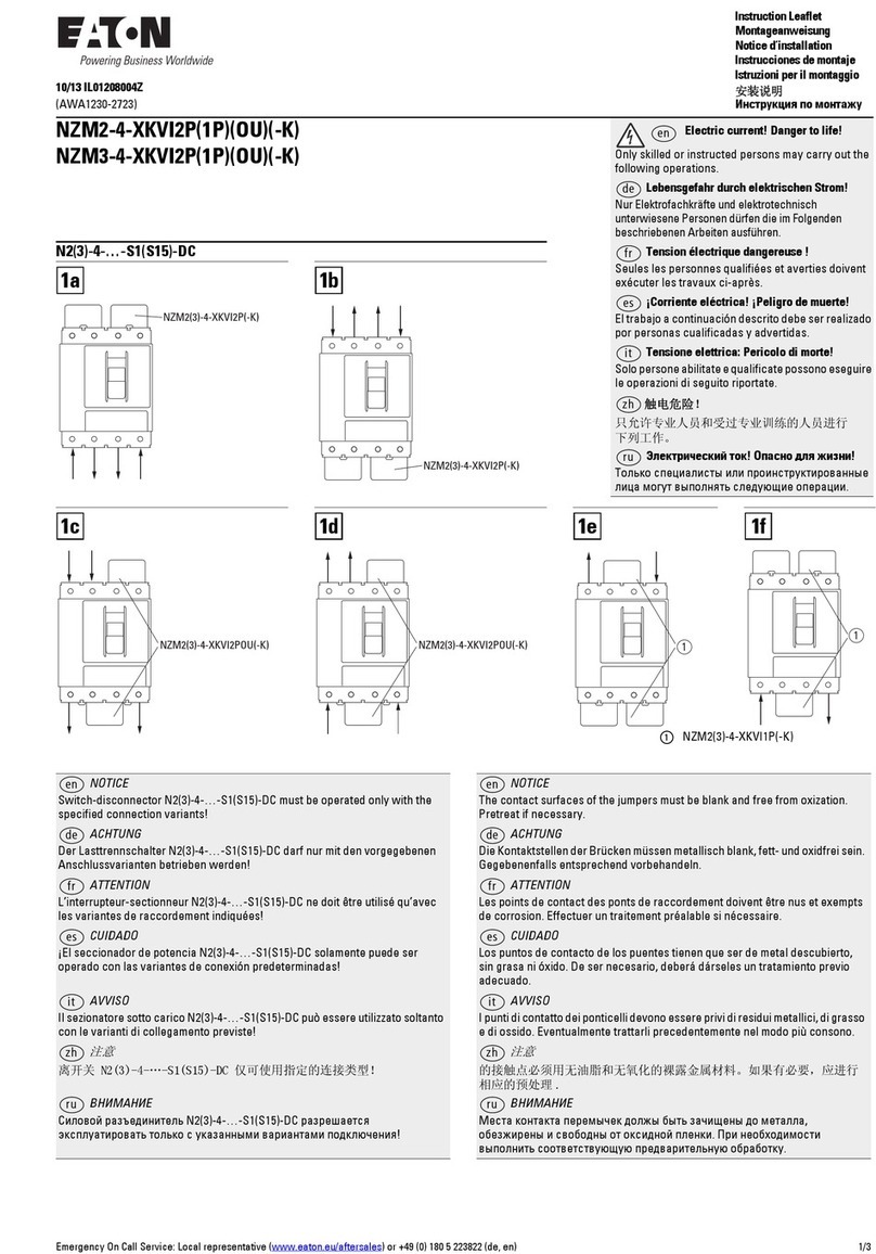
  9. Eaton Crouse-Hinds EMPX Setup guide

Eaton Crouse-Hinds EMPX Setup guide

EMPX operators
Installation & maintenance information
SAVE THESE INSTRUCTIONS FOR FUTURE REFERENCE
IF 1857
TECHNICAL DATA
This product is not intended to be used alone. The electrical apparatus or systems to which
it is being incorporated require certication as a whole when intended for use in explosive
atmospheres. The 3/4” NPSM thread joint of this product, and the thread of the equipment
to which it is being incorporated, must have a female 3/4” NPSM thread attending the
requirements for threaded joints.
ELECTRICAL SPECIFICATIONS
PUSHBUTTONS:
ILLUMINATED PUSHBUTTONS:
APPLICATION
EMPX barrel assemblies include pilot lights, pushbutton switches, illuminated pushbutton
switches, selector switches and combinations. They are used in control stations, panels
and enclosures used in areas made hazardous due to the presence of flammable vapors,
gases or combustible dusts.
IMPORTANT NOTE
When EMPX devices are to be installed in Crouse-Hinds equipment, refer to Installation
Instruction Sheet that came with that equipment for proper installation.
IF 1857 • 09/18 Copyright © 2018, Eaton’s Crouse-Hinds Division Page 1
PILOT LIGHTS:
NOTE: Verify that LED marked rating matches the socket before replacement.
ROTARY SWITCHES:
Rated voltage Ui500V
Rated current Ith 10A
Breaking capacity for AC 15
Voltage
220V
380V
500V
Current
10A
7.5A
5A
Breaking capacity for DC 13
Voltage
24V
60V
110V
220V
Current
2.75A
1.10A
0.55A
0.27A
CONTACT BLOCK INFORMATION
Rated voltage Ui500V
Rated current Ith 6A
Contacts for AC 15 Voltage
250V
Current
6A
Contacts for DC 13 Voltage
24 VDC
Current
3A
12V / 24V / 120V
Rated voltage: 250 VAC/VDC
Maximum power: 2.6W
240 VAC
Rated voltage: 240 VAC
Maximum power: 2.6W
480 VAC
Rated voltage: 480 VAC
Maximum power: 2.6W
LED SOCKET
UL application details:
Identication: Class I, Division 1, Groups B, C, D
Class II, Division 1, Groups E, F, G
Class III
Certicate: E10593
Ambient temperature range: -50°C to +60°C
Thread: 3/4” x 14 NPSM
Required threads (Class I): Eight (8) full threads engaged
Required threads (Class II and III): T Three (3) full threads engaged
Ingress protection: Type 4X
Storage temperature in original packaging: -20°C to +50°C
IECEx and ATEX application details:
Identication: II 2G Ex db IIC Gb
II 2D Ex tb IIIC Db
Certicates: Sira 18ATEX1236U IECEx CSA 18.0027U
Ambient temperature range: -50°C to +60°C
Thread: 3/4” x 14 NPSM
Required threads (EN 60079 1): Five (5) threads engaged (3/4“ NPSM)
Required threads (EN 60079 31): 3.7mm (3/4” NPSM)
Ingress Protection: IP66W (salt spray)
Storage temperature in original packaging: -20°C to +50°C
APPLICABLE STANDARDS
• UL1203 Standard for Explosionproof and Dust-ignitionproof Electrical Equipment for
use in Hazardous (Classied) Locations
• UL50 Enclosures for Electrical Equipment
• UL508 Standard for Industrial Control Equipment
• CSA C22.2 No. 25-1966 Enclosures for use in Class II, Groups E, F, G Hazardous
Locations
• CSA C22.2 No. 30-M1986 Explosionproof Enclosures for use in Class I Hazardous
Locations
• CSA C22.2 No. 94-M91 Special Purpose Enclosures Industrial Products
• CSA C22.2 No. 14-13 Industrial Control Equipment
• EN 60079-1 / IEC 60079-1
• EN 60079-31 / IEC 60079-31
Breaking capacity
for AC
Rated current
20A
AC-3 220-240V 3.0 kW
380-440V 5.5 kW
AC-15 220-240V 5A
380-440V 4A
AC-22A 220-240V 20A
380-440V 20A
AC-23A 220-240V 3.7 kW
380-440V 7.5 kW
Breaking capacity for
DC
Rated
current 20A
24V 48V 60V 110 V
Resistive
loads
T<1ms
20A 12A 4.5A 1A
Inductive
loads
T=50ms
12A 2A 1A 0.4A
Rated voltage 690V
Rated current 20A
Max. no. contact
chambers 6
MOUNTING INSTRUCTIONS
This product may not be used alone and should be installed in equipment with the
appropriate type of protection, and using the procedures described below to ensure its
degree of ingress protection.
To install the product correctly, follow the steps below:
PUSHBUTTONS (for reset pushbuttons, omit Steps 1 and 6):
1. Disconnect the contact block from the assembly by sliding the cage locking tab
clockwise.
2. Remove the nut and protective sleeve from the threaded body.
3. Place the legend plate under the knob, or attach to the enclosure.
4. Make sure the operator threads and surface being attached to are clean and free
of debris. Apply STL thread lubricant and screw the pushbutton assembly into the
enclosures 3/4” NPSM threaded entry and torque 27 in.-lbs. to 53 in.-lbs. (3 N-m to 6
N-m). Ensure legend plate is held in place to prevent rotation.
5. Install the nut onto the assembly threaded body and torque to 18 in.-lbs. (2 N-m) with
an appropriate tool.
6. Installing the contact block to the assembly:
a. With the cage locking tab held in the clockwise position, align the assembly
channel with the locking cage ID tabs on the contact block and slide the block
onto the assembly.
b. Finally move the cage tab counterclockwise to lock switch in place.
c. Verify orientation of block is such that control wires won’t be directed into ame
path of cover/body.
After performing the connections described above, the product can be safely used, and the
ingress of protection is assured.
PILOT LIGHTS AND ILLUMINATED PUSHBUTTONS:
1. Disconnect the contact/terminal block from the assembly by sliding the cage locking
tab clockwise.
2. Install LED into terminal block.
3. Remove the nut and protective sleeve from the threaded body.
4. Place the legend plate under the knob, or attach to the enclosure.
5. Make sure the operator threads and surface being attached to are clean and free
of debris. Apply STL thread lubricant and screw the pushbutton assembly into the
enclosures 3/4” NPSM threaded entry and torque to 27 in.-lbs. to 53 in.-lbs. (3 N-m to
6 N-m).
6. Install the nut onto the assembly threaded body and torque to 18 in.-lbs. (2 N-m) with
an appropriate tool.
7. Installing the contact block to the assembly:
a. With the cage locking tab oriented in the bottom, ensure it is slid to the left
position.
b. Align the assembly channel with the locking cage ID tabs on the contact block
and slide the block onto the assembly.
c. Finally move the cage tab counterclockwise to lock switch in place.
d. Verify orientation of block is such that control wires won’t be directed into ame
path of cover/body.
After performing the connections described above, the product can be safely used, and
the ingress protection is assured.
ROTARY SWITCHES:
1. Disconnect the rotary switch from the switch assembly by sliding the cage locking
tab clockwise.
2. Remove the nut and protective sleeve from the threaded body.
3. Place the legend plate under the rotary knob, or attach to the enclosure.
4. Make sure the operator threads and surface being attached to are clean and free of
debris. Apply STL thread lubricant and screw the rotary knob into the enclosures
3/4” NPSM threaded entry and torque to 27 in.-lbs. to 53 in.-lbs. (3 N-m to 6 N-m).
5. Align the rotary knob pointer to the legend plate.
6. Install the nut onto the switch assembly threaded body, but do not tighten yet.
7. Installing the rotary switch to the switch assembly:
a. With the cage locking tab held in the clockwise position, align the assembly
channel with the locking cage ID tabs on the rotary switch and slide onto the
assembly.
b. Apply pressure to the rotary switch while rotating the knob handle until the
splined shaft aligns and drops into place.
c. Move the cage tab counterclockwise to lock switch in place.
d. If the knob pointer is misaligned from the legend plate markings, the switch
assembly may need to be rotated by threading the assembly in or out while
maintaining the 27 in.-lbs. to 53 in.-lbs. (3 N-m to 6 N-m) torque requirement.
e. Torque nut to 18 in.-lbs. (2 N-m) with an appropriate tool.
NOTE: During the cables/wires installation, make sure that no mechanical tension is
applied to the rotary switch to avoid any damage.
After performing the connections described above, the product can be safely used, and
ingress protection is assured.
TYPICAL CONTACT POSITIONS
IF 1857 • 09/18 Copyright © 2018, Eaton’s Crouse-Hinds Division Page 2
!
WARNING
To avoid fire or explosion, operators must be used within their ratings, and installed by
a qualified technician.
!
CAUTION
To maintain environmental ratings, operators shall be installed in the horizontal position;
vertical position (facing up) is not permitted. Additionally, extra precaution shall be
taken if operators are stored outdoors in the vertical position.
ASSEMBLY
ASSEMBLY
NUT
KNOB
CONTACT
BLOCK CAGE
NUT KNOB
ASSEMBLY
PILOT LIGHT
HOUSING
CAGE
LED
NUT
PILOT
LIGHT
CONTACT
BLOCK
CAGE
LED
ASSEMBLY
NUT
KNOB
UNLOCKED LOCKED
ROTARY
SWITCH CAGE
NUT
KNOB
ASSEMBLY
!CAUTION
To avoid ingress, use of non-Crouse-Hinds legend plates must be verified by user.
Pushbutton and
two-position switches
1 NO & 1 NC
Three-position
switches
1 NO & 1 NC
Pushbutton and
two-position switches
2 NO & 2 NC
Three-position
switches
2 NO & 2 NC
All statements, technical information and recommendations contained herein are based on information and tests we believe to be reliable. The accuracy or completeness thereof are not
guaranteed. In accordance with Eaton’s Crouse-Hinds Division’s “Terms and Conditions of Sale,” and since conditions of use are outside our control, the purchaser should determine
the suitability of the product for his intended use and assumes all risk and liability whatsoever in connection therewith.
Eaton’s Crouse-Hinds Division IF 1857
1201 Wolf Street Syracuse, NY 13208 • U.S.A. Revision 1
Copyright © 2018 New 09/18
WIRE SIZE CHART
The chart below shows the wire size for each type of EMPX devices.
UL IECEx and ATEX
Device type
Hard wire
(up to 2
wires)
Flexible
cable
(up to 2
wires)
Hard
wire
(up to 2
wires)
Flexible
cable
(up to 2
wires) Torque
Pushbuttons and lights 18 - 13 AWG 20 - 15 AWG 2.5mm21.5mm29 in.-lbs.
(1 N-m)
Selector switches 12 AWG 14 AWG 2.5mm22.5mm29 in.-lbs.
(1 N-m)
IECEx AND ATEX SPECIAL CONDITIONS FOR SAFE USE
• For ameproof applications, the actuators and signaling elements shall only be
installed in Ex db enclosures with maximum internal volume of 35 liters and approved
for Group IIC or Ex db enclosures with maximum internal volume of 160 liters and
approved for Group IIB + H2, according to EN60079-1/IEC 60079-1.
• For ameproof applications, the actuators and signaling elements shall only be
installed in Ex db enclosures with maximum internal explosion pressure of 20 bar for
Group IIC according to EN60079-1/IEC 60079-1.
• The actuators and signaling elements shall only be used for a service temperature
range of -50°C to +60°C.
• For ameproof applications, the actuators and signaling elements shall only be
threaded in enclosure walls having a minimum length of at least ve (5) threads
engaged for 3/4” NPSM, according to Table 4 from EN 60079-1/IEC 60079-1. The
maximum thickness of the enclosure wall is limited by size (length) of the actuating
and signal elements.
• For dustproof applications, the actuators and signaling elements shall only be threaded
in enclosure wall having a minimum length of 3.7mm for 3/4” NPSM, and at least
two (2) threads engaged according to EN 60079-31. The maximum thickness of the
enclosure wall is limited by size (length) of the actuating and signal elements. The
elements have to be xed in the electrical equipment in such a way that rotation and
accidental loosening will be prevented.
• For the pilot light and illuminated buttons, the maximum load for LED is 2W.
• The outer molding of the elements has to be tightened according manufacturer’s
instructions.
• When a locknut is used, care must be taken to ensure that an engagement of two (2)
threads is still available for xing the locknut.
• The manufacturer’s instructions for operation must be followed.
STORAGE
Upon receiving the product, the parts must stored in a covered, clean and dry place so that
there is no contact between threads of the products.
INSPECTION AND MAINTENANCE
Inspection and maintenance must be performed in accordance with the applicable codes of
practice by an appropriately trained person.
REPAIR
A properly trained person shall perform the repair of equipment in accordance with the
manufacturer’s instructions and applicable codes of practice. Repair/modication must be
performed only with manufacturer original parts and should be limited to the replacement of
the following parts:
• Gasket
• Contact blocks
• Adapter for circuit breaker
• Power supply module for pilot light
• Color calotte for signaling

Other Eaton Industrial Equipment manuals

Eaton NZMB2-A Series Manual

Eaton

Eaton NZMB2-A Series Manual

Eaton PDI WaveStar TFA STS 250-600A User manual

Eaton

Eaton PDI WaveStar TFA STS 250-600A User manual

Eaton DCF 1600TWIN Instruction Manual

Eaton

Eaton DCF 1600TWIN Instruction Manual

Eaton Airflex DBB User manual

Eaton

Eaton Airflex DBB User manual

Eaton LZME Series Manual

Eaton

Eaton LZME Series Manual

Eaton ARCON ARC-EM/2.0 Manual

Eaton

Eaton ARCON ARC-EM/2.0 Manual

Eaton MEMSHIELD 4 User manual

Eaton

Eaton MEMSHIELD 4 User manual

Eaton RVAC Technical manual

Eaton

Eaton RVAC Technical manual

Eaton Airflex RTK User manual

Eaton

Eaton Airflex RTK User manual

Eaton S090ST User manual

Eaton

Eaton S090ST User manual

Eaton DILM12-XSL Manual

Eaton

Eaton DILM12-XSL Manual

Eaton ET5040 Technical manual

Eaton

Eaton ET5040 Technical manual

Eaton SL7-CB-D-M12A4 Manual

Eaton

Eaton SL7-CB-D-M12A4 Manual

Eaton Cutler-Hammer TRU-START Specification sheet

Eaton

Eaton Cutler-Hammer TRU-START Specification sheet

Eaton P1/Z Plus SVB Series Manual

Eaton

Eaton P1/Z Plus SVB Series Manual

Eaton RMQ-Titan M22-PV Series User manual

Eaton

Eaton RMQ-Titan M22-PV Series User manual

Eaton Magnum DS User manual

Eaton

Eaton Magnum DS User manual

Eaton ZB-XPLH Manual

Eaton

Eaton ZB-XPLH Manual

Eaton VoCALL 5 User manual

Eaton

Eaton VoCALL 5 User manual

Eaton COOPER POWER SERIES User manual

Eaton

Eaton COOPER POWER SERIES User manual

Eaton BBAOC-16 Manual

Eaton

Eaton BBAOC-16 Manual

Eaton PKE-XZMR Series Manual

Eaton

Eaton PKE-XZMR Series Manual

Eaton Rapid Link 5 User manual

Eaton

Eaton Rapid Link 5 User manual

Eaton TM-1-8174 Series Manual

Eaton

Eaton TM-1-8174 Series Manual

Popular Industrial Equipment manuals by other brands

Oriental motor BH Series operating manual

Oriental motor

Oriental motor BH Series operating manual

EGAmaster ROSCAMATIC 50-2 operating instructions

EGAmaster

EGAmaster ROSCAMATIC 50-2 operating instructions

Cold Jet PE50 PRE-INSTALLATION

Cold Jet

Cold Jet PE50 PRE-INSTALLATION

BilJax Pro-Jax Utility Scaffold Assembly instructions

BilJax

BilJax Pro-Jax Utility Scaffold Assembly instructions

MICROMATIC PREMIUMPLUS100 instruction manual

MICROMATIC

MICROMATIC PREMIUMPLUS100 instruction manual

Flex-A-Seal Style RKCS/D Installation, operation, maintenance guide

Flex-A-Seal

Flex-A-Seal Style RKCS/D Installation, operation, maintenance guide

TAS 3006 plus user manual

TAS

TAS 3006 plus user manual

woodmizer LubeMizer manual

woodmizer

woodmizer LubeMizer manual

Artidor AR-030 user manual

Artidor

Artidor AR-030 user manual

EGAmaster ROSCAMATIC 100-4 operating instructions

EGAmaster

EGAmaster ROSCAMATIC 100-4 operating instructions

Seifert 755501B001 user manual

Seifert

Seifert 755501B001 user manual

Trox Technik JS quick start guide

Trox Technik

Trox Technik JS quick start guide

IMS DRIVE manual

IMS

IMS DRIVE manual

matev MRM Mounting Assembly Installation Guide

matev

matev MRM Mounting Assembly Installation Guide

Kitagawa BBT200 instruction manual

Kitagawa

Kitagawa BBT200 instruction manual

Hoval ST1 INSTRUCTIONS FOR INSTALLATION, COMMISSIONING AND MAINTENANCE

Hoval

Hoval ST1 INSTRUCTIONS FOR INSTALLATION, COMMISSIONING AND MAINTENANCE

B&R PC 1200 user manual

B&R

B&R PC 1200 user manual

Siemens 3WN6 manual

Siemens

Siemens 3WN6 manual

manuals.online logo
manuals.online logoBrands
  • About & Mission
  • Contact us
  • Privacy Policy
  • Terms and Conditions

Copyright 2025 Manuals.Online. All Rights Reserved.