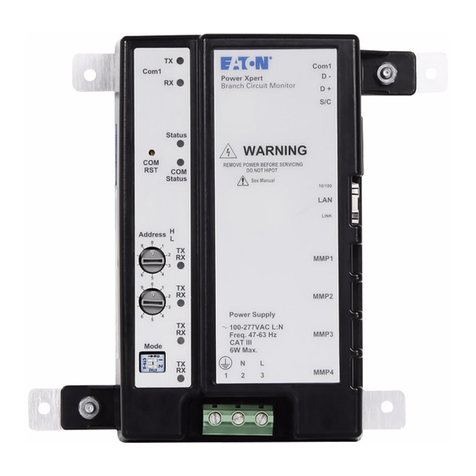
Eaton PDI WaveStar Infinity 2 Monitoring System Setup and Operation Manual P-164001106—Rev 01 v
TTaabbllee ooff CCoonntteennttss
11 SSaaffeettyy......................................................................................................................................................................................................................................................................................................................11
22 IInnttrroodduuccttiioonn....................................................................................................................................................................................................................................................................................................33
2.1 Getting Help..............................................................................................................................................3
2.2 Warranty...................................................................................................................................................4
33 CCuussttoommeerr NNeettwwoorrkk CCoonnnneeccttiioonnss............................................................................................................................................................................................................................................55
3.1 Infinity 2 Network Structure .......................................................................................................................... 5
3.2 Network Connections..................................................................................................................................5
3.2.1 Ethernet (Upstream)..............................................................................................................................5
3.2.2 Modbus RTU (Upstream)........................................................................................................................6
3.2.3 Modbus RTU Cable Specification ............................................................................................................. 6
3.2.4 Modbus RTU Cable Biasing and Termination .............................................................................................. 6
3.2.5 Modbus RTU: Daisy-chaining Monitors...................................................................................................... 8
44 CCuussttoommeerr SSeennssoorr BBooaarrdd CCoonnnneeccttiioonnss ........................................................................................................................................................................................................................ 1111
4.1 Sensor Types........................................................................................................................................... 11
4.1.1 Sensor Boards ................................................................................................................................... 12
4.1.2 Sensor Board Configuration .................................................................................................................. 12
4.2 Sensor Board Layout ................................................................................................................................. 12
4.2.1 Sensor Board Order............................................................................................................................. 12
4.2.2 Monitoring Compartments.................................................................................................................... 12
4.2.3 REPO Connection............................................................................................................................... 16
4.2.4 Sensor Base Boards and Option Boards................................................................................................... 17
4.2.5 Digital Inputs Option Board ................................................................................................................... 18
4.2.6 Relay Option Board ............................................................................................................................. 20
4.2.7 Transformer Sensor Board .................................................................................................................... 21
4.2.8 Multiple Option Boards of the Same Type ................................................................................................ 21
4.3 Sensor Board Configuration ........................................................................................................................ 22
4.4 Modbus Points List and SNMP MIB.............................................................................................................. 23
4.4.1 Downloading the Modbus Points List and SNMP MIB ................................................................................ 25
55 SSeettuupp .................................................................................................................................................................................................................................................................................................................. 22
5.1 Setup: User Administration ......................................................................................................................... 27
5.1.1 User Access Privileges......................................................................................................................... 27
5.1.2 User Setup........................................................................................................................................ 28
5.1.3 NAMES Screen .................................................................................................................................. 30
5.2 Setup: GENERAL Screen............................................................................................................................ 31
5.3 Setup: NETWORK/PROTOCOLS Screen........................................................................................................ 35
5.4 Limits: Set Analog Alarm Values .................................................................................................................. 43
5.4.1 Main Circuits and Subfeeds .................................................................................................................. 44
5.4.2 Panelboard Circuits ............................................................................................................................. 44
