Specification are subject to change without notice. Copyright 2007 Eaton Power Quality Pty Ltd
Installation Specification –SPDT60-255 Tvss Doc# 510084
Page 1 of 2
Web: http://www.powerware.com.au Phone: 1300 UPS UPS
SPDT60-255 SURGE DIVERTER
(Neutral-Earth equipotential coupler, 60/40kA)
INSTALLATION INSTRUCTIONS
FEATURES
• 1 mode plug-in protection (N-E)
• Compact solution for primary protection
• DIN43880 base, 35 mm DIN-rail mountable
• Thermally protected
• Includes dry-contact alarm
Applications
• Any SWB remote from system M.E.N.
• For use with any 275-300V L-N SPD
• Ideal companion to Eaton SPDV60-300
• Pumps or other remotely-located plant
DO NOT CONNECT TO LIVE OR ACTIVE LINES!
FUNCTIONAL DESCRIPTION
The SPDT60-255 is designed to provide protection
between Neutral and Earth circuits where Line-
Neutral protection is installed remote from the M.E.N.
link. Under normal conditions, the coupler does not
conduct, preventing earth loops and inter-circuit
coupling. Under surge conditions, the Line-Neutral
SPD(s) will conduct surge currents to Neutral,
resulting in a high Neutral voltage. At this point, the
SPDT60-255 conducts, effectively interconnecting
the circuits for the duration of the surge and shunting
the high Neutral voltage to Earth. The unit is intended
for point-of-entry or sub-board protection and may be
directly connected without fuses. The unit features a
plug-in module that may be replaced without rewiring
in the event of a fault. Check that the model you have
purchased is rated correctly for your power system.
.
This model (SPDT60-255) is designed for Neutral-
to-Earth connection only in single and 3-phase
power systems, with a grounded neutral, in the
range of 220-250V(380-440V). UNDER NO
CIRCUMSTANCES MUST THIS DEVICE BE
CONNECTED TO A LIVE OR ACTIVE LINE.
OPERATION
The operational status of the unit is shown by a flag
indicator on the front of the module. In normal
operation, the flag is green. If the unit is damaged,
the flag changes to red, indicating that replacement is
necessary. A ‘dry-contact’ alarm output is fitted to the
base unit and will change over if the module is faulty
or not in place.
WARRANTY
Eaton Power Quality warrants this unit against faulty
parts and workmanship for a period of 12 months
from the date of purchase. If this product fails to
operate correctly, please contact your Eaton
representative. This warranty doesn’t cover neglect
or intentional misuse. As this product is intended for
use in electrically harsh environments no claim is
made of suitability for purpose. This unit is designed
to reduce the likelihood of damage, not prevent it.
Please also note that an excessive surge, such as
from a direct lightning strike to the site or a power
system fault, may cause damage to the unit and
render it inoperable. A unit that has been damaged in
this way is not warrantable.
For installation details,
see over page.
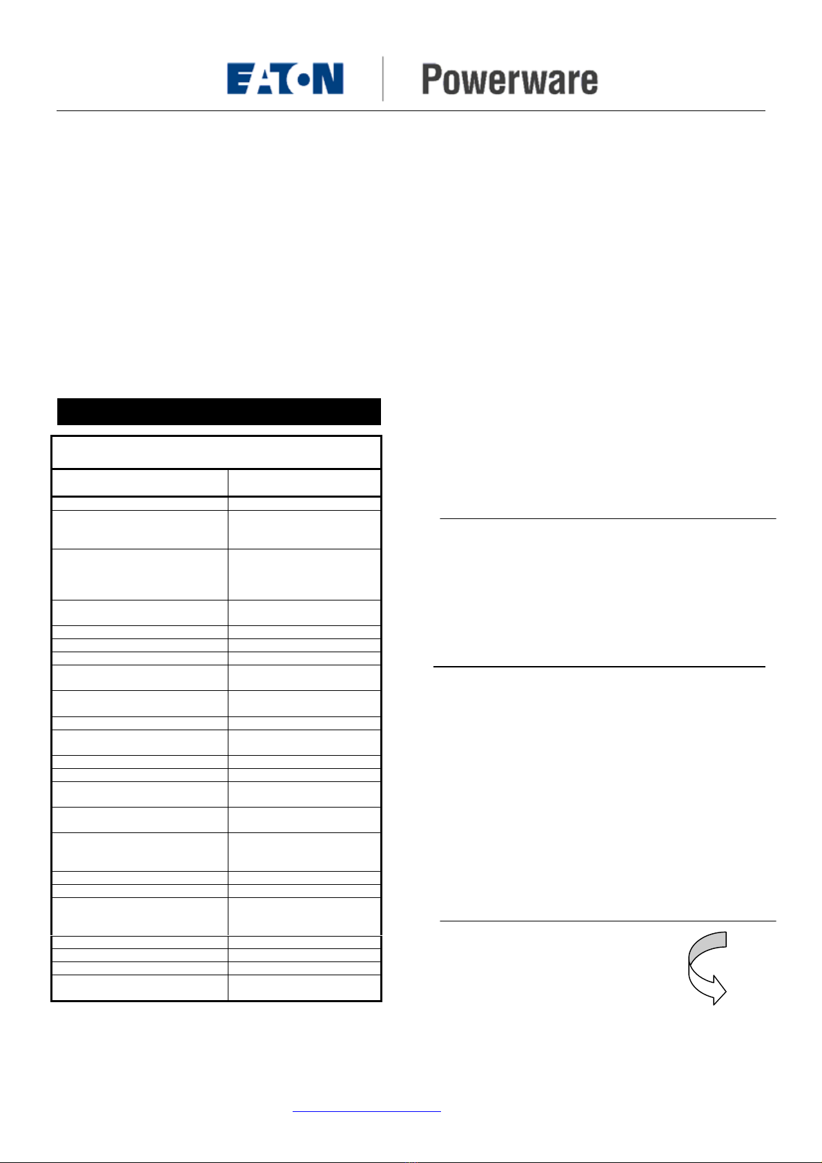
SPECIFICATIONS
Manufacturers name and model Eaton Powerware
SPDT60-255
Method of mounting Fixed. DIN Rail mount
Input voltage Neutral – Earth connection
only. System voltage 220-
250VAC (380-440V)
Maximum continuous operating
voltage – MCOV
(For this application, the
maximum neutral swing allowed)
255VAC maximum (no
conduction under load fault
conditions).
Service type Single and 3-phase with
remotely- grounded neutral
Test classification Class II
Supply current <10mA
Initial sparkover voltage 600V
Maximum rated surge current -
Ismax 8/20us 60kA
Nominal surge current - In
8/20us 40kA
Maximum Iimp – 10/350us 15kA
Residual voltage (Vpl) @ Ismax
40kA, 8/20uS 1.8kV
Nominal surge lifetime (In) 40kA (8/20uS), 20 times
Internal protection Thermal disconnector
External disconnector
requirements None
Terminations Power terminals 25mm2,
Alarm terminals 1.5mm2
Alarms/indicators Flag indicator, dry contact
alarm relay –
250VAC/24VDC, 2A
Location Category Indoor
Enclosure rating IP20
Applicable standards. IEC61643-1, IEC610006,
ANSI/IEEE C62.41,
AS1768-1991, AS3100
Dimensions DIN43880, 1 units (17mm)
Weight 100g
Environment -10 to 60C, 0-90%RH
Warranty 12 months, workmanship
and materials


