manuals.online logo
Brands
  1. Home
  2. •
  3. Brands
  4. •
  5. Eaton
  6. •
  7. Switch
  8. •
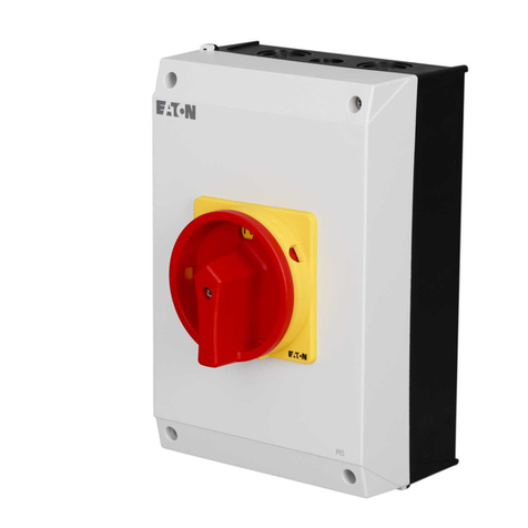
  9. Eaton ECN16A Guide

Eaton ECN16A Guide

Step Work Description
1
Turn OFF and lock out all power supplying this
switch before installing base kit.
2
Turn switch to "OFF" position.
3
Verify there is NO voltage present at the line and
load terminals using a properly rated voltage
sensing device.
4
Remove fuses.
Switch Base Replacement Instructions
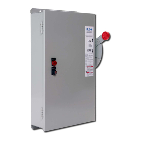
3-Pole, 30/60 AMP Fusible Safety Switches
(catalog numbers beginning w/
ECN16A,ECN160,ECN161,ECN162,ECN18A,ECN180,ECN181,ECN182,ECL12A,ECL12B,ECL12C,ECL12D,ECL13A,ECL13B,ECL13C,ECL13D,ECN36A,
ECN360,ECN361,ECN362,ECN37A,ECN370,ECN371,ECN372,ECN38A,ECN380,ECN381,ECN382,ECN430,ECN431,ECN432,ECN461,ECN462,ECN491,ECN492,EC
N521,ECN522,ECN541,ECN542,ECN561,ECN562,ECN621,ECN622,ECN641,ECN642,ECN69A,ECN690,ECN691,ECN692,ECS91Q,ECS91S,ECS94Q,ECS94S,ECS97
S,ECS97Q.
Reference Pictures & Comments
Tools Required:
Personal Protective Equipment (Gloves and Eye Protection)
Properly rated voltage sensing device.
1/4" Torque Controlled Driver with magnetic socket.
5/16" Torque Controlled Driver with magnetic socket.
Small work table and screw bin.
All work should be performed in accordance with
NFPA 70E.
Revision : 1 1 of 8
Step Work Description
Reference Pictures & Comments
5
Remove clear line shield using a 1/4" driver. (1
screw) Keep parts for reinstallation on new base.
6
Remove red arc shield using a 1/4" driver. (1
screw)
7
For fusible switches remove middle load side fuse
clip connector screw with 1/4" driver. Keep screw
for reinstallation.
8
Remove insulator screw with 1/4" driver and
remove insulator. Keep parts for reinstallation.
Insulator used only on 60 amp and 30 amp
Canadian models.
9
On fusible switches it is helpful to remove two
screws with 5/16" driver from the lower fuse base
and lower it out of the way . Keep screws for
reinstallation.
x2
Revision : 1 2 of 8
Step Work Description
Reference Pictures & Comments
10
If equipped with a neutral or control pole, loosen
mounting screw with 5/16" driver and slide to the
left. Screw is captivated by plastic base and does
not need removed.
11
Mark the line side lugs before removing so they
can be reinstalled back in their original phase
locations.
12
Remove screws from line side lugs using 5/16"
driver. Move wires to the side for base removal.
Keep screws for reinstallation on new base.
13
Remove switch base with 5/16 driver. (3 screws, 2
on bottom, 1 on top) Keep screws for
reinstallation on new base.
14
Slide base to left to disengage shaft from
mechanism. Remove insulator. Keep insulator if
present for reinstallation on new base. Insulator
used only on 60 amp models.
x2
x3
Revision : 1 3 of 8
Step Work Description
Reference Pictures & Comments
15
Verify there is no foreign material left in the
mechanism shaft coupling. This could cause
misalignment and premature failure of the new
base.
16
Remove three fuse clips with 5/16" driver and
keep for reinstallation.
17
Remove three fuse puller straps with 1/4" driver
and keep for reinstallation.
18
Remove universal base and hardware from box
verifying the following contents.
1-Universal Base
3-Lug Stops - *Not used for fusible devices.
3-Lug Stop Screws - *Not used for fusible devices.
19
Reinstall three fuse puller straps from original
base with 1/4" driver on new base assembly.
Torque to 15-25 in-lbs.
20
Reinstall three fuse clips from original base with
5/16" driver on new base assembly. Make sure
retainer tang is up as shown in picture. Torque to
20-30 in-lbs.
x3
x3
Revision : 1 4 of 8
Step Work Description
Reference Pictures & Comments
21
Rotate switch base shaft counter-clockwise to put
switch blades in open/OFF position. Place
insulator on mechanism. *Insulators used only on
60 amp models.
22
Align base mounting holes and install 3 screws
with 5/16" driver. (1 on top, 2 on bottom) Torque
to 20 to 25 in-lbs.
23
Align fuse base and install 2 mounting screws with
5/16" driver. Torque to 20 to 25 in-lbs.
24
For fusible switches reinstall insulator and and
retainer screw with 1/4" driver. The right side of
the insulator wraps around the switch base wall as
shown. Torque to 20 to 30 in-lbs. Insulator used
only on 60 amp and 30 amp Canadian models.
25
For fusible switches position load side fuse clip
connector onto the locator tabs and fasten with
screw using 1/4" driver. Torque to 20-30 in-lb.
LOCATORS
x2
Revision : 1 5 of 8
Step Work Description
Reference Pictures & Comments
26
Remove arc shield mounting screw with 1/4"
driver. Remove arc shield. Keep screw and arc
shield for reinstallation.
27
Reattach line side lugs using 5/16" driver. Torque
to 20-30 in-lbs.
28
If device has a neutral or control pole, reinstall.
Note : Two nibs on the side fit into notches on the
side of the base. Tighten mounting screw to 20 to
25 in-lbs.
29
Reattach arc shield. Torque to 20-30 in-lbs.
NIB
NIB
x3
x1
x1
Revision : 1 6 of 8
Step Work Description
Reference Pictures & Comments
30
Install line shield. Torque to 20-30 in-lbs.
31
Install fuses.
32
Verify all parts are in place and screws torqued to
specification.
33
Hold in mechanism-defeat lever and actuate
switch 3-4 times verifying switch blades are
opening and closing properly.
x1
Revision : 1 7 of 8
Step Work Description
Reference Pictures & Comments
34
Prior to energization remove any loose materials
or tools from the switch enclosure. Close cover
before turning power on ahead of switch.
Revision : 1 8 of 8

This manual suits for next models

54

Other Eaton Switch manuals

Eaton Bussmann Series User manual

Eaton

Eaton Bussmann Series User manual

Eaton RF9601 User manual

Eaton

Eaton RF9601 User manual

Eaton AT4 Series Manual

Eaton

Eaton AT4 Series Manual

Eaton Cutler-Hammer CHGENLC100ATS1SE User manual

Eaton

Eaton Cutler-Hammer CHGENLC100ATS1SE User manual

Eaton S-T0 Manual

Eaton

Eaton S-T0 Manual

Eaton P3 V/SVB Series Manual

Eaton

Eaton P3 V/SVB Series Manual

Eaton ATC-100 Installation and operation manual

Eaton

Eaton ATC-100 Installation and operation manual

Eaton EGS100L24R User manual

Eaton

Eaton EGS100L24R User manual

Eaton COOPER POWER SERIES Technical specifications

Eaton

Eaton COOPER POWER SERIES Technical specifications

Eaton XNH1-1-A Series Manual

Eaton

Eaton XNH1-1-A Series Manual

Eaton Crouse-hinds series User manual

Eaton

Eaton Crouse-hinds series User manual

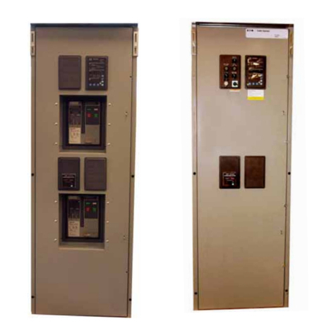
Eaton Cutler-Hammer AMPGARD User manual
Eaton

Eaton Cutler-Hammer AMPGARD User manual

Eaton Crouse-hinds series User manual

Eaton

Eaton Crouse-hinds series User manual

Eaton EATS30N User manual

Eaton

Eaton EATS30N User manual

Eaton CUTTLER-HAMMER Arcflash Reduction Maintenance... User guide

Eaton

Eaton CUTTLER-HAMMER Arcflash Reduction Maintenance... User guide

Eaton P5-125/E Manual

Eaton

Eaton P5-125/E Manual

Eaton ATC-100 Manual

Eaton

Eaton ATC-100 Manual

Eaton Magnum DS Manual

Eaton

Eaton Magnum DS Manual

Eaton RMQ-Titan M22 Series Manual

Eaton

Eaton RMQ-Titan M22 Series Manual

Eaton TM-1-8174 Series Manual

Eaton

Eaton TM-1-8174 Series Manual

Eaton Cutler-Hammer NTV Series Training manual

Eaton

Eaton Cutler-Hammer NTV Series Training manual

Eaton NZM3-XKR Manual

Eaton

Eaton NZM3-XKR Manual

Eaton Crouse-hinds series User manual

Eaton

Eaton Crouse-hinds series User manual

Eaton NZM3-XMVR Manual

Eaton

Eaton NZM3-XMVR Manual

Popular Switch manuals by other brands

HP 2610 Advanced traffic management guide

HP

HP 2610 Advanced traffic management guide

Siemens SIRIUS 3SB12 Series operating instructions

Siemens

Siemens SIRIUS 3SB12 Series operating instructions

StarTech.com ST4100USB installation manual

StarTech.com

StarTech.com ST4100USB installation manual

ATEN VS0801H user manual

ATEN

ATEN VS0801H user manual

LEGRAND PX3 installation guide

LEGRAND

LEGRAND PX3 installation guide

HydroCheck HC6000 Installation instructions manual

HydroCheck

HydroCheck HC6000 Installation instructions manual

HP 3235 installation manual

HP

HP 3235 installation manual

H3C S5120-EI Series installation guide

H3C

H3C S5120-EI Series installation guide

Intel 480T user guide

Intel

Intel 480T user guide

mCubed sensorHUB installation guide

mCubed

mCubed sensorHUB installation guide

3Com OfficeConnect Hub 12 user guide

3Com

3Com OfficeConnect Hub 12 user guide

StarTech.com Presentation Jockey Instruction guide

StarTech.com

StarTech.com Presentation Jockey Instruction guide

Radio Shack 15-1586 - Digital Optical Selector owner's manual

Radio Shack

Radio Shack 15-1586 - Digital Optical Selector owner's manual

Moxa Technologies PT-7710 Series Hardware installation guide

Moxa Technologies

Moxa Technologies PT-7710 Series Hardware installation guide

ACS KAK Technical manual

ACS

ACS KAK Technical manual

Kontron MSH8900 user guide

Kontron

Kontron MSH8900 user guide

3Com 3C16487-US datasheet

3Com

3Com 3C16487-US datasheet

Panasonic AVHS400AN - MULTI-FORMAT LIVE SWITCHER operating instructions

Panasonic

Panasonic AVHS400AN - MULTI-FORMAT LIVE SWITCHER operating instructions

manuals.online logo
manuals.online logoBrands
  • About & Mission
  • Contact us
  • Privacy Policy
  • Terms and Conditions

Copyright 2025 Manuals.Online. All Rights Reserved.