manuals.online logo
Brands
  1. Home
  2. •
  3. Brands
  4. •
  5. Eaton
  6. •
  7. Switch
  8. •
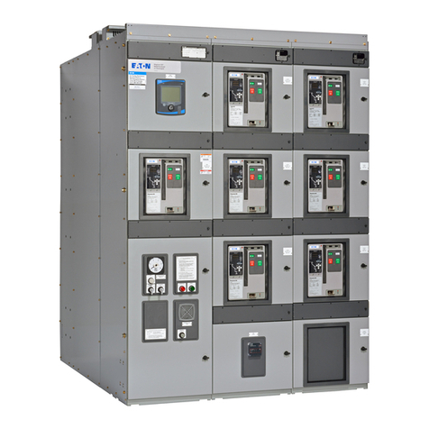
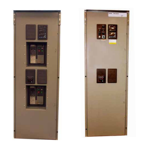
  9. Eaton Cutler-Hammer AMPGARD User manual

Eaton Cutler-Hammer AMPGARD User manual

Other manuals for Cutler-Hammer AMPGARD

1

Other Eaton Switch manuals

Eaton N2-4-S1-DC Series Manual

Eaton

Eaton N2-4-S1-DC Series Manual

Eaton 9476-ET User manual

Eaton

Eaton 9476-ET User manual

Eaton XNH00-1-S160 Manual

Eaton

Eaton XNH00-1-S160 Manual

Eaton Ulusoy URING36 F-SF6 User manual

Eaton

Eaton Ulusoy URING36 F-SF6 User manual

Eaton T ST/SVB Series Manual

Eaton

Eaton T ST/SVB Series Manual

Eaton PV-25A-4P-AC-I2/SVB-SW/N Manual

Eaton

Eaton PV-25A-4P-AC-I2/SVB-SW/N Manual

Eaton xComfort CTAA-02/01 User manual

Eaton

Eaton xComfort CTAA-02/01 User manual

Eaton Magnum DS Manual

Eaton

Eaton Magnum DS Manual

Eaton ATC-100 Installation and operation manual

Eaton

Eaton ATC-100 Installation and operation manual

Eaton RMQ-Titan M22 Series Manual

Eaton

Eaton RMQ-Titan M22 Series Manual

Eaton Crouse-hinds series User manual

Eaton

Eaton Crouse-hinds series User manual

Eaton P5-125/E Manual

Eaton

Eaton P5-125/E Manual

Eaton P5-125/E Manual

Eaton

Eaton P5-125/E Manual

Eaton P3-63/I4 Manual

Eaton

Eaton P3-63/I4 Manual

Eaton LSA-PKZ0-E Manual

Eaton

Eaton LSA-PKZ0-E Manual

Eaton XTCE080F-F47 Series Manual

Eaton

Eaton XTCE080F-F47 Series Manual

Eaton T5B Series Manual

Eaton

Eaton T5B Series Manual

Eaton XN300 User manual

Eaton

Eaton XN300 User manual

Eaton COOPER POWER LS4R Series User manual

Eaton

Eaton COOPER POWER LS4R Series User manual

Eaton WFSW15 User manual

Eaton

Eaton WFSW15 User manual

Eaton NHI-E-PKZ0 Series Manual

Eaton

Eaton NHI-E-PKZ0 Series Manual

Eaton PowerChain Management LCS Manual

Eaton

Eaton PowerChain Management LCS Manual

Eaton xComfort CTAA-02/04 User manual

Eaton

Eaton xComfort CTAA-02/04 User manual

Eaton T0 NA Series Manual

Eaton

Eaton T0 NA Series Manual

Popular Switch manuals by other brands

SMC Networks SMC6224M Technical specifications

SMC Networks

SMC Networks SMC6224M Technical specifications

Aeotec ZWA003-S operating manual

Aeotec

Aeotec ZWA003-S operating manual

TRENDnet TK-209i Quick installation guide

TRENDnet

TRENDnet TK-209i Quick installation guide

Planet FGSW-2022VHP user manual

Planet

Planet FGSW-2022VHP user manual

Avocent AutoView 2000  AV2000BC AV2000BC Installer/user guide

Avocent

Avocent AutoView 2000 AV2000BC AV2000BC Installer/user guide

Moxa Technologies PT-7728 Series user manual

Moxa Technologies

Moxa Technologies PT-7728 Series user manual

Intos Electronic inLine 35392I operating instructions

Intos Electronic

Intos Electronic inLine 35392I operating instructions

Cisco Catalyst 3560-X-24T Technical specifications

Cisco

Cisco Catalyst 3560-X-24T Technical specifications

Asante IntraCore IC3648 Specifications

Asante

Asante IntraCore IC3648 Specifications

Siemens SIRIUS 3SE7310-1AE Series Original operating instructions

Siemens

Siemens SIRIUS 3SE7310-1AE Series Original operating instructions

Edge-Core DCS520 quick start guide

Edge-Core

Edge-Core DCS520 quick start guide

RGBLE S00203 user manual

RGBLE

RGBLE S00203 user manual

Thrustmaster FLIGHT SIMULATOR X quick guide

Thrustmaster

Thrustmaster FLIGHT SIMULATOR X quick guide

Southwire SURGE GUARD 41390 RVC troubleshooting guide

Southwire

Southwire SURGE GUARD 41390 RVC troubleshooting guide

Buhler Nivotemp NT 61 Brief instructions

Buhler

Buhler Nivotemp NT 61 Brief instructions

Kramer VS-41HDCP user manual

Kramer

Kramer VS-41HDCP user manual

Techly IDATA AU-270 user manual

Techly

Techly IDATA AU-270 user manual

Belkin F1U109 user manual

Belkin

Belkin F1U109 user manual

manuals.online logo
manuals.online logoBrands
  • About & Mission
  • Contact us
  • Privacy Policy
  • Terms and Conditions

Copyright 2025 Manuals.Online. All Rights Reserved.

Effective 6/98
I.B. 48017
Cutler-Hammer
Instructions for Converting AMPGARD™Type LFM
Isolation Switch With Type 25LFR2 Design
This kit was specifically designed to replace old type LFM
isolation switches supplied prior to July, 1975, with new
type 25 LFR2 isolation switches. The shutter assembly
has been moved from the isolation switch to the starter
cell. This provides an insulating barrier over the line stabs
when the isolation switch is removed from the enclosure.
This industrial type control is designed to be installed,
operated,andmaintainedbyadequatelytrainedworkmen.
These instructions do not cover all details, variations, or
combinations of the equipment, its storage, delivery,
installation,checkout, safe operation, or maintenance.
Care must be exercised to comply with local, state, and
national regulations, as well as safety practices, for this
class of equipment.
Make certain that the incoming line breaker is locked open
and the connections to the line stabs have been de-
energized before any work is started on removal of old
parts.
Also check all auxiliary power circuits into the enclosure.
REMOVAL OF OLD PARTS
1. Rotatetheisolating switch handle counter-clockwise
90°tothe open-door position.
2. Loosendoorfastenersand open doors.
3. Remove the main power fuses and the contactor
phasebarriers.
4. Remove the contactor from the enclosure per instruc-
tionsinI.L.11-202-14under“Maintenanceand
Repair”.
5. Remove two .312 inch-18 x 1.00 inch Allen head cap
screws holding the isolation switch in place. Save
hardware.
6. Disconnect the auxiliary switch connections from the
terminal block if an auxiliary switch was originally
supplied.
7. Slide the old isolation switch out of the enclosure.
8. If any mechanical interlock linkage was supplied as
part of the original isolation switch, this linkage should
be transferred to the new switch using the holes
provided. Special care must be taken to properly
adjust the linkage so the complete mechanical
interlock system functions as originally intended.
9. See Fig. 1. Remove the 16-inch long glass polyester
line stab finger barrier that is held in place with two
.312inch-18 hex bolts. Dispose of the hardware and
thefingerbarrier.
Fig. 1 Existing Line Stab Finger Barrier
I.B. 48017
Page 2
Effective 6/98
INSTALLATION OF NEW PARTS
1. See Figure 2. Drive the four #12-14 x 2.00 inch thread
cutting screws into the holes provided in the new line
stabmolded barriers. (Twoin each molding) Back
these screws out approximately .250 inch.
Fig.2 New Line Stab Molded Barrier
Fig.4 Enclosure Front View
2. See Fig. 3. Install the L.H. line stab molded barrier to
the line stab support molding using two .250 inch-20 x
.62 inch hex bolts, lockwasher and flat washer from
the kit.
3. See Fig. 3. Attach the right-hand line stab molded
barrier under the .312 inch-18 x .62 inch hex bolt,
lockwasher and flat washer from the kit. Do not
tightenthishardware.
4. Use the shutter assembly as a template to correctly
positionthe right-hand line stab moldedbarrier. Place
the keyholes over the heads of the #12-14 x 2.00 inch
screws and drop into place. Tighten the .312 inch-18
hardwaresecurely.
5. Remove the shutter assembly.
6. Assemble the .125 inch thick top rear finger barrier
(4.88wide)and the bottom rear barrier(3.50inch
wide). Select the top and bottom barriers (3.88 inch
wide)(depending on thetype of cutoutrequired, if any)
and snap into place.
7. Mount the shutter assembly by again placing the
keyholes over the #12-14 x 2.00 inch screws. Drop
into place and tighten the #12-14 x 2.00 inch screws
securely.
8. Locate and drill one .257 inch diagram hole in the top
front channel of the cell as shown in Figure 4.
Fig. 5 Shutter Operating Lever Assembly
Fig. 3 Existing Line Stab Barrier Assembly
9. See Figure 5. Drop the keyhole slot in the end of the
shutteroperating lever over theheadof the shoulder
bolt on the shutter assembly.
Top FrontChannel
.250-20HexNut&Lockwasher
.375-16x1.12 Fil.Hd.
ShoulderBolt
ShutterOper.
Lever
.375-16 Flexloc
Roller must be
free to rotate
7.75
.03Approx.
I.B. 48017 Page 3
Effective 6/98
10. Assemble the shutter operating lever to the top front
channel using the shoulder bolt, .250 inch-20 hex nut
andlockwasher in thepreviously drilled .257 inch hole.
Note that the shoulder bolt is assembled in the
second hole from the end of the shutter operating
lever with a 7.75 inch dimension to roller.
11. Check that shutter is free to move when latch is
released. Rollershould rotate freely onshutter
operatinglever. Shutteroperatinglever should be free
of friction.
12. TheType 25 LFR2 isolation switch should have a light
coatingorsilicone grease (W 53846BU orDow
Corning#4 Compound) on thecontactarea of the line
stabs. This lubrication makes the switch easier to
operate and protects the contact surfaces.
13. Slide newType 25 LFR2 isolation switch into the
structure and secure with .312 inch -18 x 1.00 inch
socket head cap screws from the old unit. Connect
auxiliary switch leads to the terminal block, (if used).
14. Replace contactor in the structure. Push in firmly to
engage stabs. Replace the three .312 inch -18 bolts
connecting the contactor load terminals to the current
transformers.
15. Replace the multi-point low-voltage control plug in its
receptacle on the right-hand side of the contactor.
16. Replace thecontactorphase barriers and the motor
starting current limiting main fuses.
17. Before energizing starter, be sure themechanical
interlock between the isolation switch and the
contactorfunctions as described inI.L. 11-202-14 and
I.L.16-200-21.
18. Refer toI.L. 16-200-21 for isolation switch interlock
adjustmentprocedure.
I.B. 48017
Page 4
Effective 6/98
PrintedinU.S.A./CCI
Cutler-Hammer
221 Heywood Road
Arden, NC 28704