1
Instruction Manual IM02602008E - Rev. D
Transformer Temperature Controllers IM02602008E - Rev. D May 2019 www.eaton.com
1. Introduction
The content of this manual is organized into seven sec-
tions, and three appendixes, as follows:
•Introduction
•Installation
•Operating Functions
•Operating Procedures
•Maintenance and Repair
•Troubleshooting
•Specifications
•Appendix A - Programming Quick Reference Guide
•Appendix B - Modbus Registers
1.1 Product Overview
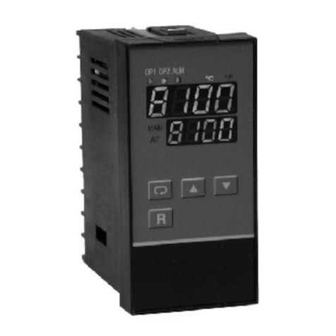
Eaton®Transformer Temperature Controllers monitor the
temperature of up to three ventilated, dry-type transformer
windings. They also monitor the ambient temperature with-
in the cabinet in which the transformer is installed.
These temperatures are detected by thermocouples placed
within the transformer windings and inside the cabinet.
If winding temperatures exceed a preset limit (setpoint)
relays are tripped to start cooling fans to reduce tempera-
tures and prevent equipment damage. If higher trip and
alarm winding temperature setpoints are reached, Form C
contacts may be used to trip a remote alarm and ultimately
trip the transformer offline.
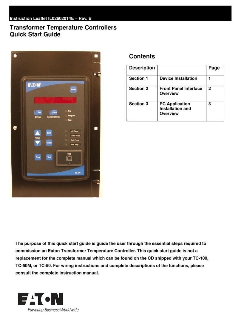
Three models of the transformer temperature controller
(TC) are available; the TC-50, the TC-50 Modbus, and the
TC-100. The TC-100 includes Modbus and has advanced
features for discrete inputs, monitoring, and data logging.
All models have a common appearance but vary in function-
ality. The functionality described in Section 4.1.2 -Operating
the TC Manually, and Section 4.2 -Local Operation, apply to
all models unless otherwise noted in a heading or the text.
All TC models have a front panel that provides a communi-
cations interface between the controller and an operator.
The panel consists of an 9-character LED display, 9 discrete
LEDs, and 9 pushbuttons. Communication is also possible
using a laptop computer connected to a front USB port, or
through Modbus (on the TC-50 Modbus, and the TC-100
models
A sealed controller unit processes all data received.
All TC models are available in two versions: a barrier cabi-
net version (Section 1.2) or a flush, bezel-mounted version
(Section 1.3).
The features of each model are described below.
All models (TC-50, TC-50 Modbus, and TC-100) have these
standard features:
•Operates on 100 to 240 Vac, 50 or 60 Hz power.
•LED display shows conditions and values
•Panel LEDs indicate system status.
•Cooling fans turn on automatically when temperatures
exceed a setpoint, or a trip relay shuts down the trans-
former.
•Setpoints can be used to turn on either fan, or turn on an
Alarm or Trip relay for a high temperature condition.
•Alarm and trip relays can function as fail-safe relays (nor-
mally energized when the TC is powered up).
•Alarm buzzer sounds but can be silenced without cancel-
ing the alarm.
•Certifications include Underwriter’s Laboratories (UL®), to
Standard 873, CSA C22.2 No. 24-93.
•Provides 4-20 mA analog signal for remote indication or
use with SCADA systems.
•Unit can be used for single-phase transformers, or other
devices, by selecting or deselecting individual elements.
•Fans can be operated automatically for short periods to
prevent motor seizing.
The TC-50 Modbus model has all of the standard features,
plus:
•RS-485 connection for Modbus communications.
The TC-100 model has all of the standard features, plus
these additional features:
•RS-485 connection for Modbus communications.
•Monitors two discrete inputs, such as opening or closing
fan louvers or doors.
•Provides automatic monitoring and logging functions, and
temperature trending, to analyze operation and achieve
faster restoration.


