9
2*M3-6 screw/螺栓
4*M3-8 screw/螺栓
M5-10 screw/螺栓
M5-10 screw/螺栓
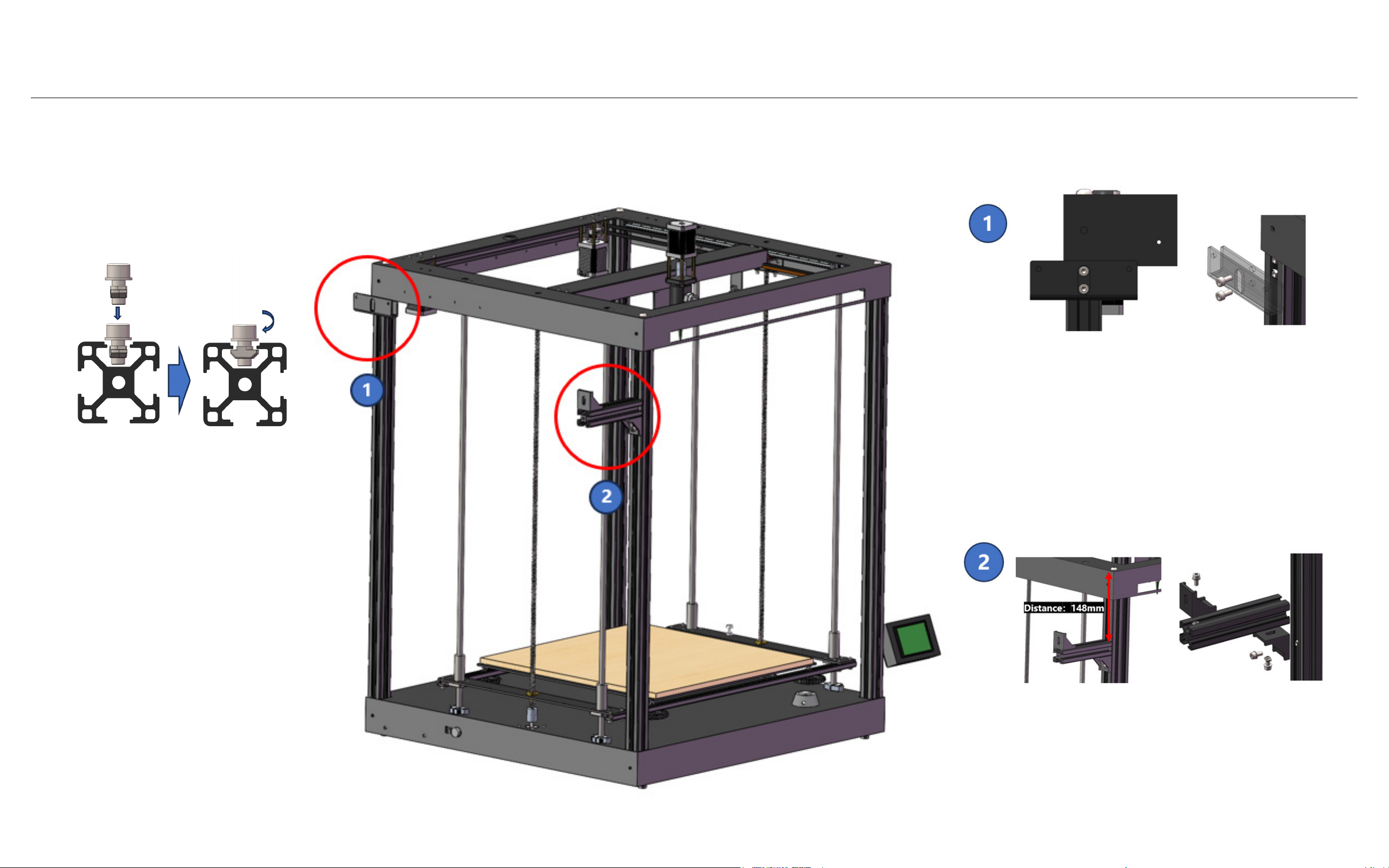
第二步:零件组装
Step 2 - Parts Assembly
11.使用图示参考标识机器的正面。现在,我们开始组装
零件。
16. 将挤出器安装到支架上。
12. 使用2颗M3-6螺栓在每根螺纹杆上组装Z轴顶部轴
承,并紧固轴承上的小黑色螺丝。
17. 将触摸屏连接到机器右侧的相对应电线接口,并用
M5-10螺栓和T型螺母固定。
13. 拆下X轴顶部盖子。
18. 在机器左侧安装推杆挂板,并用2颗M5-10螺栓和T
型螺母固定。
14. 拆下X轴限位开关,连到X轴限位电线(参考电线图
示)。
19. 将推杆部件插入推杆挂板,并用M5-10螺栓固定。
15. 使用4颗M3-8螺栓固定挤出器支架(共4颗),然
后重新安装X轴盖子。
20. 添加进料管和木质平台(请勿撕掉膜)。
11. Identify the front face of your machine
using the diagram reference. Now, let’s
start assembling the parts.
16. Put the extruder into the holder.
12. Assemble the Z-axis top bearing on
each screw rod using 2 M3-6 bolts, and
tighten the small black screws on the
bearing.
16. Connect the touch screen to the
cables on the machine’s right side, and
secure it with an M5-10 bolt and T nut.
13. Unscrew the top X-axis cover.
18. Install the putter hanging plate on the
machine’s left side, and secure it with 2
M5-10 bolts and T nuts.
14. Unscrew the X-axis limit switch, and
connect it with cable X (refer to the ca-
ble diagram).
18. Insert the putter into the putter hang-
ing plate, and secure it with lock bolt
M5-10.
15. Attach the extruder holder with M3-8
bolts (4 in total) and screw back the
X-axis cover.
19. Add the feeding tube and MDF plat-
form (do not remove the film).