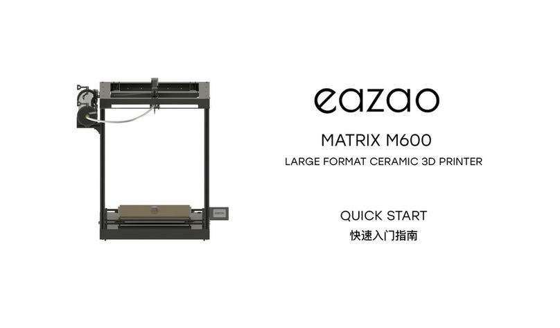
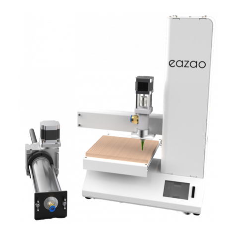
Eazao MATRIX M700 User manual

LARGE FORMAT CERAMIC 3D PRINTER
QUICK START
MATRIX M700
快速入门指南

https://www.eazao.com
欢迎使用Matrix陶瓷3D打印机手册。
本手册将引导您逐步完成组装3D陶瓷打印机的过程,并为您的首次打印提供指导说明。
为了您的安全,请在操作机器之前仔细阅读整个手册。
Welcome to the Matrix Ceramic 3D Printer manual.
This manual will guide you through the step-by-step process of assembling your 3D clay printer,
as well as provide instructions for your first print.
For your safety, please read the entire manual before operating the machine.

3
Introduction
Aluminium Profile
Z Axis Smooth Rod
Z Axis Screw Rod
z 轴光轴
全彩触摸屏
z 轴丝杆
铝型材
Y轴电机
电动推杆
挤出机
X轴电机
调平螺母
打印平台
喷嘴设定器
Y Axis Motor
Leveling Nut
Printing Platform
Nozzle Setter
Electric Putter
Extruder
X Axis Motor
Full Color Touch Screen
送料管
Feeding Tube
简介

4
Parameter
Technical Principle/ 技术原理 DIW (Direct Ink Writing)/ 陶瓷无模直写
Molding size/ 成型空间 500 x 500 x 700 mm (L x W x H)/( 长 x 宽 x 高 )
Cartridge Volume/ 料筒容积 5 L / 9 KG
Layer thickness/ 层厚 0.4 -1mm
Feeding method/ 送料方式 Electric putter+Screw extrusion/ 电动推杆 + 螺杆挤出
Nozzle diameter/ 喷嘴直径 1.6-3.3 mm
Printing speed/ 打印速度 10mm/s - 40mm/s
Supporting materials/ 支持材料 Pottery or porcelain clay, Viscous uid/ 陶泥、瓷泥等粘滞流体
Operating system/ 支持操作系统 Windows, Mac, Linux
Slicing software/ 切片软件 Cura, Slic3r, Simplify3D etc
Support le format/ 支持文件格式 .STL, .Gcode, .OBJ etc
Interactive mode/ 交互方式 Full color touch screen, SD card, USB connection/ 全彩触摸屏,SD 卡 , USB 联机
Input voltage/ 输入电压 100-120Vac/200-240Vac~50/60Hz
Output voltage/ 输出电压 24V/15A Max 360W
Machine size/ 机器尺寸 900 x 1200 x 1100 mm(L x W x H)/( 长 x 宽 x 高 )
Package dimensions/ 包装尺寸 1000 x 900 x 500 mm(L x W x H)/( 长 x 宽 x 高 )
Package weight/ 包装重量 56KG
参数

5
Machine Accessories
全金属挤出机
hAll metal Extruder
料筒盖子 卡箍
lCartridge Cover mClamp*2
底座
电机减速器
顶部
5L 料筒
Z轴打印平台
料筒固定座 密封圈&密封固定块
铝型材
防旋法兰 推力块
丝杆*2 & 光轴*4 全彩触摸屏
aBase
iMotor reducer
bTop
j5L Cartridge
cZ-axis Printing Platform
kCartridge Holder nSealing Ring & Sealing Block
dAluminium Profile*4
oAnti-Rotation Flange pThrust Block
eScrew Rod*2 &Rod*4 gTouch Screen
机器配件
挤出机支撑
fExtruder Holder

6
Machine Accessories
送料管
wFeeding Tube
喷嘴设定器
xNozzle Setter
电机减速机连接线
pMotor Reducer Cable
螺纹推杆
oThreaded Push Rod
六角扳手*6电源线
推杆挂板 推杆固定板 联轴器 螺栓螺母包 夹子
丝杆固定轴承
@7Allen Key*6zPower Cable
qPutter Hanging Plate rPutter Fixing Plate sCoupling uBolt Nut Kit vClips*2tScrew Fixed Bearning
机器配件
USB数据线
yUSB Data Cable
料筒铝型材
@8Cartridge Aluminum Profile
料筒转接
@9Cartridge Adapter
5L垫片
#05L Gasket

7
Machine Upgrading Accessories (Gifts)
The#1,#2,#3 are upgrade parts for the Z-axis side plan and do not require installation./#1,#2,#3零件为Z轴侧边方案升级零件,无需安装。
The #4 and #5 parts are direct extrusion upgrade solutions and do not require installation./#4 和#5零件为直接挤出升级方案,无需安装。
The #6 and #7 parts are spare parts for the extruder and do not need to be installed./#6 和#7零件为挤出机备用零件,无需安装。
The inner diameter of the free nozzle is: 1.6, 1.9, 2.3, 2.5, 3.0, 3.3mm./赠送的喷嘴内径为:1.6、1.9、2.3、2.5、3.0、3.3mm。
Z轴侧边限位螺栓 直接挤出接头 直接挤出板 挤出机O型圈 ACE挤出机套筒
#3Z-axis side limit bolt #4Direct Extrusion Connector #5Direct Extrusion Plate #6Extruder O-ring #7ACE Extruder Sleeve
润滑脂*Micro SD卡*
$1Grease*$0Micro SD*
Z轴侧边限位 Z轴侧边限位连接线
#1Z-axis side limit #2Z-axis side limit cable
* 这个物品可能根据某些地区的海关政策受限。如果您无法在包装中找到该物品,我们建议您联系当地的零售商寻找类似的产品。
*This item may be restricted according to custom policies in certain regions. If you are unable to locate the item in the packaging, we kindly suggest contacting your local retailer for similar products.
喷嘴*12*
#9Nozzle*12*
SD卡读卡器
#8SD Card Reader
针管*
$2Needle*
密度板*
$3MDF*
机器升级配件 (赠品)
* 本页面配件为机器升级配件,为赠品。因机器版本不同存在差异,如果缺失等问题,不予补发。
*The accessories on this page are machine upgrade accessories and are given as gifts. There are differences due to different machine versions. If there are problems such as missing, reissue will not be issued.
胶带
$5Tape
束线带
$4Zip Ties
绕线管
$6Bobbin

8
4*M8-10 screw/螺栓
1. 将底座放在平坦的桌面上。
6. 放置Z轴打印平台。
2. 将底座旋转90度。
7. 使用4颗M8-10螺栓固定顶部,确保电机与电源开关
处于同一侧。
3. 从包装中取出4根铝材。
8. 安装4根Z轴光轴。
4. 使用4颗M8-10螺栓将每根铝材与底座固定。
9. 安装2根Z轴丝杆。
5. 将底座旋转回正面朝上的位置。
10. 在每个螺纹杆底部加装Z轴联轴器,并确保牢固地
拧紧。
1. Place the base on a flat and even sur-
face.
6. Place the Z-axis printing platform in
position.
2. Rotate the base by 90 degrees.
7. Secure the top using 4 M8-10 bolts,
ensure that the motors are on the same
side as the power switch.
3. Take 4 aluminum profiles from the
package.
8. Insert 4 Z-axis smooth rods.
4. Fasten each aluminum profile to the
base using 4 M8-10 bolts.
9. Insert 2 Z-axis screw rods.
5. Rotate the base back to its original
position, facing up.
10. Attach a Z-axis coupling at the bot-
tom of each screw rod and ensure it is
tightly fastened.
第一步:主体组装
Step 1 - Main Body Assembly
4*M8-10 screw/螺栓

9
2*M3-6 screw/螺栓
4*M3-8 screw/螺栓
M5-10 screw/螺栓
M5-10 screw/螺栓
第二步:零件组装
Step 2 - Parts Assembly
11.使用图示参考标识机器的正面。现在,我们开始组装
零件。
16. 将挤出器安装到支架上。
12. 使用2颗M3-6螺栓在每根螺纹杆上组装Z轴顶部轴
承,并紧固轴承上的小黑色螺丝。
17. 将触摸屏连接到机器右侧的相对应电线接口,并用
M5-10螺栓和T型螺母固定。
13. 拆下X轴顶部盖子。
18. 在机器左侧安装推杆挂板,并用2颗M5-10螺栓和T
型螺母固定。
14. 拆下X轴限位开关,连到X轴限位电线(参考电线图
示)。
19. 将推杆部件插入推杆挂板,并用M5-10螺栓固定。
15. 使用4颗M3-8螺栓固定挤出器支架(共4颗),然
后重新安装X轴盖子。
20. 添加进料管和木质平台(请勿撕掉膜)。
11. Identify the front face of your machine
using the diagram reference. Now, let’s
start assembling the parts.
16. Put the extruder into the holder.
12. Assemble the Z-axis top bearing on
each screw rod using 2 M3-6 bolts, and
tighten the small black screws on the
bearing.
16. Connect the touch screen to the
cables on the machine’s right side, and
secure it with an M5-10 bolt and T nut.
13. Unscrew the top X-axis cover.
18. Install the putter hanging plate on the
machine’s left side, and secure it with 2
M5-10 bolts and T nuts.
14. Unscrew the X-axis limit switch, and
connect it with cable X (refer to the ca-
ble diagram).
18. Insert the putter into the putter hang-
ing plate, and secure it with lock bolt
M5-10.
15. Attach the extruder holder with M3-8
bolts (4 in total) and screw back the
X-axis cover.
19. Add the feeding tube and MDF plat-
form (do not remove the film).

10
第二步:零件组装
Step 2 - Parts Assembly
Install 5L cartridge aluminum profile
安装5L 料筒铝型材
Install T-Nuts.
安装T型螺母
First, fix the bolt and the
T-nut, then put the T-nut into
the groove of the aluminum
profile in a parallel direction,
and quickly tighten the bolt
clockwise so that the T-nut
rotates 90° in the aluminum
profile and gets stuck in the
groove of the aluminum pro-
file.
首先将螺栓与T型螺母固定,让后
将T螺母平行方向放入铝型材的槽
内,顺时针快速拧紧螺栓,使T型
螺母在铝型材内旋转90°卡在铝型
材槽内。
The distance between the beam profile and the top
is 112mm.
横梁型材与顶端距离为112mm。
Use 2 M5-10 bolts and T-nuts to install the putter
hanging plate.
使用2个M5-10的螺栓和T型螺母安装putter挂板。

11
第二步:零件组装
Step 2 - Parts Assembly
Install T-Nuts.
安装T型螺母
First, fix the bolt and the
T-nut, then put the T-nut into
the groove of the aluminum
profile in a parallel direction,
and quickly tighten the bolt
clockwise so that the T-nut
rotates 90° in the aluminum
profile and gets stuck in the
groove of the aluminum pro-
file.
首先将螺栓与T型螺母固定,让后
将T螺母平行方向放入铝型材的槽
内,顺时针快速拧紧螺栓,使T型
螺母在铝型材内旋转90°卡在铝型
材槽内。
Install four diagonal braces.
安装四根斜撑。

12
第三步:组装说明
Step 3 - Assembly instructions
1. Please refer to the electric putter assembly instructions for electric putter assembly: https://www.eazao.com/downloads/
1.电动推杆组装请参见电动推杆组装说明书:https://www.eazao.com/downloads/
2After installation is completed, grease can be applied to the Z-axis screw and the screw of the electric putter.
2.装完成后可以在Z轴丝杆和电动推杆的丝杆上涂抹润滑脂。
3.The feeding tube passes through the elongated slot at the top to prevent the feeding tube from interfering with the printing model.
3.送料管从顶部细长槽孔内穿过,防止送料管与打印模型发生干涉。
*Refer to the assembly and usage tutorial video: https://youtu.be/i4ZXauQAjDc?si=CGB6e4aOyWJfy2bQ
*参考组装和使用教程视频:https://youtu.be/i4ZXauQAjDc?si=CGB6e4aOyWJfy2bQ

13
第四步:电压档位
Step 4 - Voltage Range
In this state, the voltage is 115V, which is
suitable for countries such as the United
States, Canada and Japan.
此状态下为115V电压,适用于美国,加拿大和日
本等国家。
In this state, the voltage is 230V, which is
suitable for countries such as China, Germa-
ny and the United Kingdom.
此状态下为230V电压,适用于中国,德国和英
国等国家。
Warning:
Before turning on the power for the first time, you must check whether the
power supply voltage complies with local standards! ! !
If the voltage gear is wrong, it will burn the circuit.
警告:
第⼀次打开电源前,必须检查电源电压是否符合当地标准!!!
如果档位错位,会烧毁电路。

14
第五步:接线
Step 5 - Cables
Insert the X-axis motor cable: Connect the 4-core ca-
ble marked with X number to the X-axis motor.
插入X轴电机线:将标有X号码的4芯线缆与X轴电机连接。
Insert the E-axis motor cable: Connect the 4-core ca-
ble marked with E number to the E-axis motor.
插入E轴电机线:将标有E号码的4芯线缆与E轴电机连接。
Plug in the Nozzle Setter Cable: Insert the cable
marked with the Z number.
插入喷嘴设定器线:将标有Z号码的线对插。
Insert the Y-axis limit cable: Connect the 3-core cable
marked with Y number to the Y-axis limit switch.
插入Y轴限位线:将标有Y号码的3芯线缆与Y轴限位开关连接。
Inserting the electric putter cable: insert the electric
putter cables.
插入电动推杆线缆:将电动推杆的线缆对插。
Insert the Y-axis motor cable: Connect the 4-core ca-
ble marked with Y number to the Y-axis motor.
插入Y轴电机线:将标有Y号码的4芯线缆与Y轴电机连接。
Insert the X-axis limit cable: Connect the 3-core cable
marked with X number to the X-axis limit switch.
插入X轴限位线:将标有X号码的3芯线缆与X轴限位开关连接。
Insert the screen cable: Insert the screen cable into the
screen rear case, pay attention to the direction.
插入屏幕线缆:将屏幕线缆插入屏幕后壳中,注意方向。

15
第六步:平台调平
Step 6 - Platform Leveling
Place the nozzle setter on the center of
the printing platform. (The nozzle setter
needs to be removed after the nozzle is
triggered.)
将喷嘴设定器放置在打印平台中央位置。(
喷嘴触发后需要将喷嘴设定器移走。)
Before leveling, you need to ensure: the
distance between the nozzle and the
printing platform > 30mm.
调平前需要保证: 喷嘴与打印平台距离 >
30mm。
Click point1,2,3,4,5 in turn to perform
leveling.
依次点击point1,2,3,4,5,进行调平。
The nozzle will first move to the cen-
ter of the build platform, triggering
the nozzle adapter. Then the nozzle
moves to point1.
喷嘴会首先移动到打印平台中央,触发
喷嘴适配器。然后喷嘴移动到point1。
Turn on the power on the back of the
printer and click "Tool".
打开打印机背部电源,选择“Tool”。
When printing for the first time, level-
ing is required and select "Leveling".
首次打印,需要进行调平,选
择“Leveling”。
Adjust the four leveling nuts under the
printing platform to adjust the distance
between the nozzle and the platform to
0-0.1mm.
调节打印平台下方的四颗调平螺母,使喷嘴
与平台的距离调整为0-0.1mm。

16
第七步:打印前准备
Step 7 - Prepare for Printing
Equipment assembly:
1. Install the electric push rod and fill it
with clay.
2. Install the electric push rod on the side
of the printer and insert it into the feeding
tube.
Clay pre-extrusion:
1. Click "Tool" -> "Putter" -> "Load", the
clay enters the extruder from the feeding
pipe.
2. After the clay enters the extruder, click
"Shutdown" to stop feeding, and click
"Back".
3. Click "Extrusion" -> "In", the extruder
starts to extrude clay.
4. After the clay is smoothly extruded from
the nozzle, click "Shutdown" to stop extru-
sion, and click "Back".
设备组装:
1.安装电动推杆,并装填陶泥。
2.将电动推杆安装在打印机侧边,并插入送料
管。
陶泥预挤出:
1.点击“Tool”->“Putter”->“Load”,陶
泥从送料管进入挤出机。
2.陶泥进入挤出机后,点击“Shutdown”停止
送料,点击“Back”。
3.点击“Extrusion”->“In”,挤出机开始挤出
陶泥。
4.陶泥从喷嘴顺畅挤出后,点击“Shutdown”
停止挤出,点击“Back”。
Clay pre-extrusion settings, select
"Tool".
陶泥预挤出设置,选择“Tool”。
Click "Putter" and "Extrusion" re-
spectively to pre-extrude the clay.
分别点击“Putter”和“Extrusion”,
进行陶泥预挤出。
"In", the extruder feeds material,
"Out", the extruder returns material.
"shutdown", the extruder stops.
“In”,挤出机送料,“Out”,挤出机
退料。“shutdown”,挤出机停止。
"Load", the putter moves forward,
"Unload", the putter moves back-
ward. "Shutdown", the putter stops.
“Load”,推杆前进,“Unload”,推
杆后退。“shutdown”,推杆停止。

17
第八步:开始打印
Step 8 - Start Printing
1. After confirming the printing,
the nozzle moves to the center of
the printing platform.
2. The nozzle setter needs to be
manually placed in the center of
the printing platform. After the
nozzle setter is triggered, remove
the nozzle setter.
1.确认打印后,喷嘴向打印平台中央
移动。
2.需要手动将喷嘴设定器放置在打印
平台中央,喷嘴设定器触发后,将喷
嘴设定器移走。
If you are not satisfied, you can move
the printing platform down through
"Tool" -> "Move" -> "Z+".
如不满足,可通过“Tool”->“Move”-
>“Z+”,向下移动打印平台。
Before starting to print, you need to
ensure that the distance between the
nozzle and the printing platform is >
30mm.
开始打印前,需要确保:喷嘴与打印平台距
离 > 30mm。
To start printing, select "Printing".
开始打印,选择“Printing”。
To use a USB card reader, please
click "USB".
使用USB读卡器,请点击“USB”。
Select the sliced "Gcode" file to
print.
选择切片好的“Gcode”文件进行打
印。

18
第八步:开始打印
Step 8 - Start Printing
If the first layer of clay cannot be attached to the printing platform, the following opera-
tions can be performed.
Click "Option" -> "Babystep" -> "Z-" to move the printing platform up so that the first
layer of clay is attached to the printing platform. (The range is switched to 0.1mm)
如果打印首层陶泥无法附着在打印平台上,可进行如下操作。
点击“Option”->“Babystep”->“Z-”,将打印平台向上移动,使陶泥首层附着在打印平台
上。(量程切换到0.1mm)
Switch the touch screen language: Click "Settings", click "Language", and select the lan-
guage you need.
切换触摸屏语言:点击“Settings”,点击“Language”,选择您需要的语言。
1. Babystep settings/ Babystep设置
2. Language settings/ 语言设置

19
M700M700
M700M700
M700M700
M700M700
第九步:切片软件设置
Step 9 - Slicing Software Settings
1. Software download and install/ 软件下载和安装
According to the computer operating system, it is recommended to download and install the latest version of Cura software:
https://ultimaker.com/software/ultimaker-cura/
根据电脑的操作系统,下载并安装 Cura 软件最新版本:https://ultimaker.com/software/ultimaker-cura
2.Add a printer/ 添加打印机
How to change the language of slicing software.
如何更换切片软件的语言。
Preferences > Congure Cura ...
偏好设置 配置Cura
After selecting the language you need, you
need to restart the Cura software.
选择您需要的语言后,需要重启Cura软件。
Select "Non UltiMaker printer"
选择"Non UltiMaker printer"

20
Please use a 12G needle.
请选择12G喷嘴。
M600M600
第九步:切片软件设置
Step 9 - Slicing Software Settings
Start G-code
G21 ;set units to millimeters
G90 ;absolute positioning
M82 ;set extruder to absolute mode
G28 ;Home
G1 Z25.0 F1500 ;move the platform down 15mm
G92 E0 ;extruder reset
G1 F300 E5
G92 E0 ;The extruder is forced to zero again
M302
M163 S0 P0.87; Set Mix Factor
M163 S1 P0.13; Set Mix Factor
M164 S0
End G-code:
G92 Z0
G1 F1500 Z10
G28 X0 Y500 ;move X Y to min endstops
M82
M84 ;steppers off
Set the printer and extruder parameters as shown in the gure, the conguration of Start G-code and End G-code
can copy the text below.
如图所示设置打印机和挤出机参数,Start G-code和End G-code的配置可以复制下方文本。
Refer to the gure to congure the visibility of the
slicing software settings.
参照如图,配置切片软件设置可见性。
Table of contents
Other Eazao 3D Printer manuals